manuals.online logo
Brands
  1. Home
  2. •
  3. Brands
  4. •
  5. Midway
  6. •
  7. Arcade Game Machine
  8. •
  9. Midway 3A948 User manual

Midway 3A948 User manual

--
qt)MIDWAY MAY2000
16-3A948A-101
www.midway.com
Ei:JiTiCJN
Installation Instructions for
:,
,,'
:'
U:
pgrade
Kit
3A948
TM
Upgrades
Rush
2049:
Tb·
-:·
Rush
·
20/49
Tournament
Edition
Install
kit
on
Rush 2049 models33336, 32936 & 30136
Copyright
@
2000
Midway
Games
West
Inc.
All
rights
reserved.
Midway Games West Inc.
675
Sycamore Drive MIipitas, California 95035 USA
6/1
/00 -1-
.....
SAFETY
INSTRUCTIONS
The
following
safety
instructions
apply
to
the
upgrade
kit
installer.
Read
these
Instructions
before
attempting
to
Install
this
kit.
Other
safety
instructions
appear
throughout
this
ma~ual.
. . ,
DEFINITIONS
OF
SAFETY
TERMS
WARNING
indicates
a
potential
hazard.
If
you
fail
to
avoid
this
hazard,
ft
could
cause
death
or
serious
injury.
CAUTION
Indicates
a
potential
hazard.
If
you
fail
to
avoid
this
hazard,
it
may
cause
minor
or
moderate
injury
.
CAUTION
also
alerts
you
about
unsafe
practices.
NOTICE
indicates
information
of
special
importance.
&
WARNING:
QUALIFIED
SERVICE
PERSONNEL
ONLY.
This kit requires installation
of
components
in
the
primary
AC
circuit.
Improper
Installation
of
these
parts
can
result
in
a
shock
hazard.
Installation
must
be
performed
by
a qualified
service
technician.
The
technician
must
strictly
adhere
to
this
manual's
instructions.
,.
. -' . -
. '
'
&
WARNING:
DISCONNECT
'
POWER.
Tum
the
power
off
and
unplug
the
VGM
(video
game
machine)
before
attempting
to
install
this
kit.
Installing
or
repairing
PC
boards
with
power
on
can
damage
components
and
void
the
warranty.
Be
sure
that
you
securely
install
ground
wires.
, ·
&
WARNING:
INSTALL
GROUND
WIRE.
Reduce
the
risk
of electrical
shocks!
Properly
ground
the
metal
mounting
bracket for the
LED
display.
•-
&
WARNING:
AVOID
.
E:LECTRIC:AL
:SH09KS:
This
video
game
system
doesn't utilize
an
isolation
transformer:
·internal, cabinet
AC
isn't isolated
from
the
external,
AC
line.
c2r
' .,..... . -.
..
; . ' ' : ' • · : ,
..
..
...
NOTICE:
The
term
VQM
refers
.
to th
.e
video
game
machine.
: ; ' ' '
~
. . ' ' . .. '
ABOUT
UPGRADE
KIT
3A948
The
Rush
2049
Tournament
Edition
kit
adds
sever~I
important
.
features
to
your
VGM
(video
game
machine)
...
•
An
LED
display
on
top
of
the
cabinet •
New
game
PIC
• A
modem
inside
the
cabinet • A
new
game
EPROM
•
An
update
disk
drive
During
kit
Installation,
you
connect
the
VGM's
disk
to
the
Rush
2049
Tournament
Edition
kit
disk.
The
Rush
2049
Tournament
Edition
kit
disk
becomes
the
master,
The
VGM
disk
becomes
the
slave.
You
save
your
VGM's
player
data
onto
the
new
Rush 2049 Tournament EditiondisK.
You
then
replace
the
·
original
disk
.
6/1/00 -2-
MAIN
CABINET
ASSEMBLY,
REAR
VIEW
SHOWING
MAJOR
PARTS
FROM
THIS
KIT
3A948
20-10732
01-15302-1
,a,),,-
LEFT
LEt
0
·i?li~y
,,,
',
SPACER,
ALUMINUM~(
DISPLAY
BRACKET,
MARQUEE
SUPPORT
BRACKET
01-15302-2
DISPLAY
BRACKET,
RIGHT
4010
-01100-20 /
TAMPER
RESISTANT----...,_
(
10-32x1-1/4
BH
y
4108-01193-
10B
SMS
#8x5/8
TR
Not included
in
this
view..
,
5850-14052-00
5556-15272-00
5827-15144-00
04-13028
Adapter,
IEC/NEMA
Cord
Bead,
Ferrite
(4)
Block,
2-Circuit
Terminal
Board,
MIPSMPS
Modem
,..
I
~
I
~
I
I
I
I
I
I
I
6/1/00 -3-
20-10631
A-23841°
H-23624.1
H-23885
H~23885
FlJ\T
WASHER
.265x.625x.067
SCREW
8-32x1/2
P-PH
SEMS
POWER
SUPPLY
(SEE
DETAIL
DRAWING)
4108-01193-108
;;
SMS
#Bx5/8
TR
01-15303
POWER
SUPPLY
MOUNTING
BRACKET
I
r6
A-23882
120V
AC
LEO
OISPI.J\Y
CABLE
&
AC
POWER
BRICK
Cable,
Modem
Chipset,
Update
(Assy)
Harness,
Fluorescent
Lamp
Adapter
Harness,
RJ-11
Serial
Adapter
Wire,
Green
Ground
PARTS
LIST
Item Part# Qty Item
Part#
Qty
ARTWORK
0
Artwork,
Backlit
Marquee
31-3639.1 1
ELECTRONICS
0
Artwork,
Foil
31-3646 3 0
Board,
MIPS/MPS
Modem
04-13028 1
0
Decal,
Backlit
marquee
31-3640 1 0
Brick,
Display
AC
Power
A-23882 1
CJ
Decal,
Keypad
Update
31-3641 1 a
Chipset,
Update
(Assy)
A-23841 1
O
Decal,
Seat
Back
31-3642 1 0
Display,
LED
20-10728 1
••
•
h.
0 Instructions,
Backlit
Bezel
31-3640 1 O
Drive,
Programmed
Hard
A-23864 1
CABLES MECHANICS
0
Adapter,
IEC/NEMA
Cord
5850-14052-00 1 0
Bracket,
LED
Left
01-15302-1 1
O
Cable,
Modem
20-10631 1 0
Bracket,
LED
Right
04-13085 1
0
Cable,
Ribbon
5795-16508-00 1
□
Bracket,
Pwr
Brick
Mtg
01-15303 1
O
Harness,
Fluor
Lamp
Adptr
H-23624.1 1 0
Clamp,
½"
Cable
03-7655-8 1
0
Harness,
Hard
Drive
Y-Pwr
H-23805.1 1 0
Wrench,
Tr/TX
T25
20-10144 1
O
Harness,
RJ-11
Serial
Adptr
H-23885 1
0
Wire
,
Green
Ground
H-23895 1 MISCELLANEOUS
o
Bead,
Ferrite
5556-15272-00 4
DOCUMENTS 0
Block,
2-Circuit
Terminal
5827-15144-00 1
O
Card,
Game
Registration
16-10650 1 0
Clamp,
1/2"
Dia
.
Cable
03-7655-8 1
0
Flyer,
Safe
HOD
Handling
16-10811 1 o_comainer,
Hard
Drive
Ship
08-8068 1
O
Man'I,
Rush
Tourn
Kit
(This)
16-3A948·
101
1 0
Pad,
Update
Cushion
04-13065 1
O
Sheet,
Caution
Elec
Device
16-10077 1 O
Spacer
,
Aluminum
20-10628 2
0
Template,
LED
Display
16-11133 1
NOTICE:
You
can
link
Rush 2049 Tournament Edition
VGMs
to
other Rush 2049
Tournament Edition
VG
Ms.
You
can't link
to
non-Tournament
Edition
VG
Ms.
' '
,,
·
6/1
/00 -4-
.....,
NOTICE:
If
you're updating a video game machine (VGM) that currently generates
revenue: The hard drive contains vital, player data that you must transfer
to
the new
drive.
Player
data
includes
many
important
items
...
•All
player accounts at the VGM's
location. •Player passwords. •Player names. ·Total miles driven.
•Total
coins collected.
•Best race times. •And more. The VGM uses player data to unlock additional tracks and
cars for players. Bottom line: Player data represents a
considerable
investment by avid
players. If you don't transfer player data, you'll let down your players, and you'll
disappoint them. Transferring player data is extremely important, both to your players
and to your profits.
INSPECT UPGRADE KIT 3A948
[ ) 1. Kit 3A948 upgrades a
Rush
2049 VGM
to
an
Rush
2049
Tournament
Edition
VGM. Unpack the
upgrade kit from the carton and check for damage. Check the parts list to be sure that you have a
complete upgrade kit 3A948.
c2r
NOTICE:
Check
you/
~pgrade(kifharidri~e
·. Do you have
Rush
2049
Tournament
Edi-
tion software? If not, return the'drive to
arf
authorized distributor for a replacement.
..
c2r
' .
..
•· : , · ,
.,(,
.
,.
,;
NOTICE:
Leave EPRPM.s
in
th~.
pro.te
.ct.ive package until you're ready to install them.
Store the devices that you remove
in
'the paCkaglng from this upgrade kit.
c2r
NOTICE:
Before moving the VGM, shut off VGM power. Then allow the hard drive to
spin down for 30 seconds.
Never
move the VGM with the power on, or with the disk
spinning.
PREPARE FOR TOURNAMENT OPERATION
(l 2.
[l3.
[l
4.
Register your new PIG chip with the Midway office at 773-961-1493.
To
register, give the Midway
office your PIC number and your arcade name and address.
Fill out the
Rush
2049
Tournament,Edition
registration packet. The packet includes your location
name, game serial number, checking account number, etc.
Sign up for tournament play by mailing your registration packet to the Midway® Chicago office.
Or
you may phone in the informatfon·by calling
the
Midway® office at 877-MPN-2WIN or 877-676-
2946. The office must receive and accept your packet before your VGM can achieve network
access.
[]
5.
Verify operation
of
the VGM. If necessary, make repairs so that the
VGM
operates properly.
[)
6. Take a phone with you to test the phone line. Also take phone splitters, SuperStats sheets and
your installation tools.
[ ] 7. Make sure that the location has
a,:i
analog phone lin~ nearthe game. Check to see that the phone
can call Midway Tournament Netviork
(MTN)
at 877~6'76-2946. (This is a toll-free call.)
6/1/00 -5-
.....
[]
8.
[] 9.
Find
the three pieces
of
foll artwork.
Remove
the
backing
from
the first
foil
piece.
Apply
the
foil
to
the
left side of the marquee. Start
at
the top
of
the
foil
and
work
downward. After you've positioned
the foil,
smooth
it
outwards.
Take
care
to
squeeze out'air bubbles. If
you
can't remove a bubble,
pop
it
with
a knife or
pin
.
Then
smooth
the
bubble
down.
Allow
the
adhesive to
set.
Now
apply foils
to
the
right
side
of
the
marquee. Apply
the
third
foil
to
the
raised
area
atop
the
player panel. This
area
is
just over the steering
wheel
shaft.
Unbolt
and
remove
the
old
seat-back ·artwork..
Replace
it
with
the
new
artwork
from
the
kit.
[] 1
o.
Note
the
old
bezel
instructions beside
the
monitor.
Unbolt
and
remove
these instructions. Replace
them
with
the
new
instructions
from
the
kit.
[]
11.
Find
the
new
keypad
overlay
in
the
kit.
Remove
the
overlay's adhesive backing. Carefully apply
the
new
overlay over
the
old
keypad
overlay.
[]
12.
If you're upgrading
an
game
that people
have
played,
proceed.
If
you're upgrading a
new
(never
played)
game,
skip
ahead
to
Install Chips.
[] 13. Write
down
the
Stats
and
SuperStats.
(Press
and
hold
Music
for
5
seconds.
While pressing,
add
VIEW
#1,
then
VIEW
#2
and
the.n
y1Ew
#3.)
.
[] 14.
Log
on
as
joint
Team
Rush
and'play ~-gain~·.
(Yo~;II
.neea'tiie record
of
this
game
later.
It
will help
you
to
verify that player data
tra'riste
·
rs
to
the
new
hard
.drive.) Write
down
your
PIN
# (personal
Identification number).
See
your
Rush
manual
1·
6-30036-101
for
more
details about logging
on.
[ ]
15.
Note
coin
settings,
the
cabinet number
ai:,d
other.settings. After installation,
the
settings revert
to
default values. ···
31-3646
DECAL,
MTN
FOIL
(3)
-~---,,,
6/1/00 .-6-
31-3639
_,_,_
__
BACKLIT
MARQUEE
31-3640
DECAL,
BACKLIT
INSTRUCTIONS
31-3642
DECAL,
SEAT
BACK
INSTALL CHIPS
NOTICE:
Installing new software clears a number of important game options. These
include coin options, control calibration, audio settings, statistics and the
VGM
cabinet
number. Write down any of these settings that
you
want
to
reuse.
RJ-11
,
TO
L
ED
·
DISPLAY
-----1
ADAPTER
RINGO
CPU
BOARD
00
DENVER
1/0
BOARD
□
BOOT
R
OM
(REPLACE)
U27
EXPANSIO
N
MIPSMPS
M
OUNTING
SCREWS
MIPSMPS
MODEM
BOARD
ON
TOP
OF
DE
NV
ER
1/0
[)
16, Switch off power to the
VGM
. Disconnect the line cord from the AC power. Clear the work area.
..._,
[ ] 17. Open the
VGM
's back door. If this is a linked cabinet, disconnect the linking cables. (You'll recon-
nectthem after kit installation.) ··
[ ] 18. Remove the Phillips screws from the card cage door. Fold down the card cage door.
[ ] 19. Locate the socket for the memory circuit
in
one corner of the Ringo CPU Board,
CPU
BOARD
ALIGN NOTCHES
6/1/00 -7-
[]
20. Use a chip extraction tool
to
remove
EPROM U27
on
the Ringo
CPU
· .Board. Gently rock the chip until it
becomes loose
in
its socket. Remove
the chip from the Ringo CPU Board.
[]
21
. Locate the EPROM labeled
Rush
2049 Tournament Edition U27 Boot.
Remove the protective packaging.
Orient the chip over the empty socket.
Align the notches on the chip and
.socket. Insert the chip pins into the
socket. Press the chip firmly to seat
it.
[]
22.
Use
a chip extraction tool
to
remove
the
PIC
at Denver
1/0
Board location
U18.
Gently rock the
chip until it becomes loose
in
its socket. Remove the chip
from
the Denver
1/0
Board.
[]
23
,
Find
the
new
PIC
chip
in
the upgrade
kit.
Remove the protective packaging. Orient the PIC over
the empty socket.
Align
the notches
on
the chip
and
socket. Insert the chip pins into the socket.
Press the chip firmly
to
seat
it.
~
NOTICE:
Boot
ROM
and
PIC
chip
notches must face
away
from
one
another.
INSTALL
LINE-VOLTAGE
AC
WIRING
&
WARNING:
QUALIFIED
SERVICE
PERSONNEL
ONLY.
This kit requires installation of
components
in
the primary
AC
circuit. Improper installat
ion
of these parts
can
result
in
a
shock hazard. Installation must
be
performed
by
a qualified service technician.
The
technician must strictly adhere
to
this manual's instructions.
. .
',
, •.,
,·.
. ..
~
'
..
.
~
:
&
WARNING:
DISCONNECT
POWER.
Turn
the power off
and
unplug the
VGM
(video
game
machine)
before attempting
to
install this,
kit.
Installing wiring with power
on
can
damage components
and
void the
w~rranty.
[ ]
24.
Use
one screw
to
hold the
card
cage door
up
.
[ ]
25.
Find
the
VG
M power supply
and
bracket
at
the
base of the cabinet.
Unplug
the fluorescent lamp
cable
from
the
VG
M power
supply.
, 4608-01081-.11
[] 26.
#8x11/16
H-F
SCREW--,......
-
Three H-F screws fasten the
VGM
power supply
(REMovE)
and bracket
to
the cabinet wall.
Remove
.these
.
screws.
[]
27.
Remove the
VGM
power supply.
and
bracket
from
the cabinet.
[]
28.
Leaving wires connected, unscrew the eight-tab
terminal block from the power supply bracket.
[]
29.
Locate the 12-tab terminal block:
'i
n·the kit~
Pbsl~
'
tion the
new
block where the ·eight-tab terminal
block
was
on
the
VGM
power supply. Mount the
12-tab terminal block.
...
.....
,..
6827-15144·00
TERM
I
NAL
BLOCK
GROUND
WIRES
WARNING:
Avoid
afire hazard! Wire the terminal block properly,
and
check your work!
Connect only black wires
on
one side of the terminal block. Connect only white wires
on
the other side of the terminal block. Otherwise
you
may create a short circu
it.
Sparks
from
a short circuit
can
start a
fire.
. 6/1'/00 -8- ·
...
.
WHITE
(4)
OLD TERMINAL BLOCK
BLACK
(4)
WHITE
(
6)
NEW TERMINAL BLOCK
[ ] 30. Disconnect one wire
from
the
old
terminal block. Connect the wire
to
the equivalent tab of the
new
terminal block. One by one, reposition the o_ther wires
on
the
new
terminal block.
Use
the old termi-
nal
block
as
your guide.
Be
sure that
you
move
the wires
to
equivalent tabs
on
the
new
terminal
block.
[]
3'1.
Find
the fluorescent lamp adapter-cable
In
the
kit.
Connect the harness
to
two of the
new
terminal
block's free pins.
Be
sure
that white wires only connect
to
white wires. Black wires must only con-
nect
to
black wires.
If
necessary, check your connections
with
an
ohmmeter. Never connect black
and
white wires together.
WARNING:
INSTALL
GROUND
WIRE.
Reduc~ the risk of electrical shocks! Properly
ground the metal mounting bracket for the
LED
display.
[ )
32.
Attach the green ground wire
to
the power supply bracket's threaded ground stud. (Other green
ground wires already connect to this stud.) Use
an
#8-32
KEPS
nut.
[ ] 33. Route the green ground wire across the
bo~om
ofthe cabinet.
~
. ..:. '
·,
.. .'
[]
34.
Replace
and
remount
the
VGM
power supply
in
the cabinet.
[ ]
35.
Plug the fluorescent lamp cable irito the fluoresp~nt lamp adapter cable.
. .
_,
,,
' . { , ..-·
ROUTE LED DISPLAY CABLES
Denver
1/0
:
RJ-11
Adapter
Board
P7
Data
Cable
LED
Display I
c,.,,....,,-'<=...,.._,.,
..
,-=-~
[ ]
36.
Remove the six screws that retain the backlit marquee. Set the screws
and
attract shield aside.
(You'll need
them
later.) ·
[]
37. Disconnect the fluorescent lamp harness
from
the fluorescent lamp assembly.
[]
38.
Stuff the lamp harness
and
connector through-the cable hole
in
the blue marquee housing.
[]
39.
Remove the rear marquee support
panel
by
removing the six mounting screws.
6/1/00
-9-
.,.
,
CABLING
THE
LED
DISPLAY
MARQUEE
SUPPORT
BRACKET
FLAT
WASHER
.265x.625x
.
067
04-13085
GROUND
DISPLAY
BRACKET
,
RIGHT
5556-15272-00
FERRITE
BEADS
H-23895
GROUND
WIRE
SCREW
1/4-20x1-1
/ 4
TAMPER
RESISTANT
H-23885
SERIAL/RJ
11
ADAPTER
HARNESS
03-7655-8
CABLE
CLAMP
04-13028
20-10732
/
,
SPACER,
ALUMINUM
-...
t-,
. DI
SP
LAY
CABLE
..
....,
...
',
20-10634
LEO
DISPLAY
01-15302-1
DISPLAY
BRACKET,
LEFT
-.., 4010-01100-20
1
,,,---
TAMPER
RESISTANT
v
10-32x1-1/4
SH
4108-01193-10B
SMS
#B
x
5/8
TR
MARQUEE
LIGHTBOX
ASSEMBLY
20-10657
TELEPHONE
"
T"
ADAPTER
, 2
JACK
20-10631
_.----
MODEM
CABLE
MIPSMPS
BOARD
--ifttt--:)~~_J
5556-15272·00
FERRITE
B
EAD
A-23864
HARD
DRIVE
DISK---ttr~~~
fl
5795-16508-00
HOD
DUAL
DRIVE
RIBBON
CABLE
03-10045
----
-#8x
11/16
SPACER
(2)
4008-01005-22
SCREW
8-32
x
1-3/8
P
-P
H
(2)
A-23882
fil:;;~~--\--~sc----
FLUORESCENT
LIGHT
LED
DISPLAY
CABLE
ASSEMBLY--tr,;.
(SEE
DETAIL
DWG)
4108-01193·
108
SMS
#8x5/8
TR
~
I
J I f .
20-10730
MODULAR
DATA
CABLE
7'
20-10727
120V
AC
ADA
PTER
AMS
I
I 01-15227
POWER
ADAPTER
MO
UN
TING
BRACKET
CABLE
H-23624.1
"'---...,.."'---
FLUORESCENT
LIGHT
5850-14052-00
IEC/NEMA
POWER
ADAPTER
CORD
ADAPTER
[]
40.
Remove
the
four
screws
th
at
retain
the
blue
marquee
housing.
These
screws
are
beside
the
fluo-
rescent
lamp
fixture.
Tilt
the
marquee
to
the
down
position.
[] 41.
Remove
the
two
bottom
screws
from
the
marquee
housing
. Lift
off
and
set
aside
the
housing
.
6/1/00 -10-
[)
42.
Return
the
marquee
to
the
upright position.
Place
the
supplied, hole-drilling template
on
the
cabi-
net
according
to
instructions
on
the
template.
Take
care
to
set
up
the
template
so
that
your
drill
misses
the
picture
tube.
~
WARNING:
H
ANDLE
CRT
WITH
CARE.
If
you
break
a
CRT,
it implodes! Shattered
glass
can
fly
over
eight feet
from
the
implosion.
() 43.
[] 44.
[] 45.
Use
a hole
saw,
rather
than
a
drill
bit,
for
this
step.
Followi
ng
the
template illustration, drill a
1-
1/2"-diameter
hole
in
the top
of
the
cabinet.
Drill
a
second 1-1/2"-diameter
hole
in
the
back
of
the
marquee light
box
.
These
holes
will
be
near
the
APPLY
TEMPLATE
#1
marquee.
You'll
route
harnesses
throug
_h.
these
·
APPLY
holes
and
to
the
LED
display.
Also
drill
the
pilot
TEMPLATE
#2
holes for bracket installation.
Remove
the
tem-
plates.
Plug
the
IEC
/
NEMA
connector
Into
the top
of
the
VGM
power
supply.
Find
the
AC
power
brick
and
the
power
brick
bracket
in
the
kit.
Lay
the
power
brick
·
on-the
floor
.
of
the
cabinet.
Position
the
brick
,near
the
cabinet
side
opposite
the
main
power
supply.
Use
the
bracket
to
mount
the
brick
to
the
cabinet floor.
[]
46. Connect
the
AC
power
brick
to
the
free
end
of
the
IEC
/
NEMA
cord
adapter.
'
.•
' '
[] 47.
Find
the
RJ-11
adapter cable
in
·
the
'
lit.'
Attach
the
RJ-11
adapter cable
to
the
LED
data
cable.
1, ;
,.
. , .. .
:·
[] 48.
Route
the
RJ-11
adapter cable
through
the
JAMMA
opening
in
the
chassis.
[] 49. Connect
the
RJ-11
adapter
cabl~
:
te>
co.nneptor
P7
on
the
Denver
1/0
Board.
[] 50.
Route
the
LED
power
and
data cables
up
the template
side
of
the
cabinet.
Find
the
loose,
green
gr
ound
cable
in
the
bottom
of
the
cabinet.
Route
this
with
the other cables.
RJ-11
AD
APTE
R
DENVER
1/0
60ARO
~
- - -
_1=_=_=_=_=_~
~-=-=_=_~_l=S[a=RI
AL
P7
---7
[] 51.
Fasten
the
cables
to
the
cabinet
wall
under
the
base
of
the
monitor.
Use
the
·
supplied
cable
clamp.
[] 52. Slide
the
LED
cables
through
the
new
hole
on
the
top
panel.
. L
PHONE
LINE
pg
tr
DIP
.
SWITCHES
I
□
r--
7
;,..__
__
_.,_TO
ANAL
OG
1"187l
-:
[] 53. Insert
the
LED
cables
into
the
marquee
through
the
speaker
hole.
[] 54.
Run
the
LED
cables out of
the
marquee
through
the
new
hole
in
the upper
mar-
· ·
quee
panel.
6/1
/00 -11-
~
PIC
I
(
REPLACE)
:
.
MIPSMPS
MOUNTING
S
CREWS
I
I
P11
[
MIPSMPS
MODEM
BO
A
RD
ON
TOP
OF
DENVER
1/0
GAME
TO
GAME
LINK
[]
55,
Near the new hole is a display mounting bracket. Notice that this bracket includes a ground stud.
Slip the green ground wire's ring terminal over the ground stud. Use a KEPS nut to secure the
ground wire to the display mounting bracket.
[ ] 56, Install a ferrite bead
on
the
9VAC,
LED power cable. Position the bead near the connectors that
plug into the LED display. Route the cable through the center of the ferrite bead. Now loop the
cable over the top
of
the bead. Then.
run
the cable throught the center
of
the bead again.
To
com-
ply with FCC regulations, the cable must
run
through the bead twice.
[]
57. Dress the cable away from the
271'
:nionitor. Use the supplied 1/2"-diameter cable clamp and SMS
#Bx
11/16 screw.
[J58. Connect the LED power cable to the LED display.
[]
59. Install a ferrite bead
on
the LED data cable. Position the bead as close
to
the cable connector
as
possible. Route the cable through the center of the ferrite bead. Now loop the cable over the top of
the bead. Then
run
the cable throught the center
of
the bead again.
To
comply with FCC regula-
tions, the cable must
run
through the bead twice.
[ ] 60. Connect the LEDdata cable to the LED display.
INSTALL
THE
LED
DISPLAY.
..
~
I :
NOTICE:
LED
display iMtallation is a two-man job.
.
.'
' ! , . . t
,·; ,:, • ,,
~
NOTICE: The displayi
h~u5.ing
.
is
f~j~ly
soft aluminum. When installing the marquee
brackets, take care not'to over-tOrque the screws. Otherwise, you might strip screw
holes or screws.
[)
61.
Attach a display bracket
to
the side of the display without cables. Use a 1/2" long spacer between
each bracket and the display. Fasten the bracket to the display side with
#1
O,
tamper-resistant
machine screws.
[ ] 62. Attach a display bracket to the
.cabl
e side of the display. Take care to keep the ferrite beads
between the display and the bracket. Use the same type hardware as with the other bracket.
[ ]
63.
Keep the LED display with the marquee. Temporarily fold the marquee down
on
top of the cabinet.
.[] 64. Reassemble the blue marquee housing. Use the original six screws.
[]
65. Fold the marquee into its upright position. Meanwhile, leave the display resting on the top of the
cabinet.
[ ] 66. Use with four SMS #8 x 5/8
scr~viis
·
lor
this·
kt~h:
F~~te~
the template-side LED display bracket to
the cabinet. Drive the screws into the template holes.
[]
67.
If necessary, drill mounting holes for the other LED display bracket. Now mount the other bracket.
[ ] 68. Reassemble the rear marquee support panel by replacing the six mounting screws.
6/1/00 -12-
[]
69. Reconnect the fluorescent lamp harness.
[]
70. Insert the new marquee art behind the marquee shield.
[J
71
. Attach the marquee shield and new backlit·ma~quee
t~
the marquee housing.
INSTALL THE MODEM
Game-to-
Game
Ethernet
I
,<•~
··
1-
.,,.,..,_
1.,,i
..
.. - 0 ~
=u
--
~~..
~
....~,.~~·......... '
Analog
Phone
Line
[]
72. Unscrew and discard two screws mounting the Denver 1/0 Board. These screws flank gun connec-
tors
P12
and
P13.
[] 73. Notice the 96-pin connector on the bottom
of
the Modem Board. Now find the Denver 1/0 Board's
96-pin connector P9. Install the Modem Board
over
the Denver 1/0 Board by mating these two
connectors.
[ ] 7
4.
Secure the Modem Board with'
tWo
·screws':
a.ht!
space
ts from the kit.
[] 75.
[) 76.
Route the modem cable through the linking cable hole in the cabinet. Run the cable up near the
card cage.
Install a ferrite bead
on
the modem cable. Position the bead eight inches from the modem board
end
of
the cable. When you reinstall the card cage, this bead must remain outside the card cage.
Route the cable through the center of the ferrite bead. Now loop the cable overthe top
of
the bead.
Then run the cable throught the center
of
the bead again.
To
comply with FCC regulations, the
cable must run through the bead twice.
[]
77. Run the bead end
of
the modem cable through the card cage's linking hole.
[]
78. Plug the modem cable into connector
J1
on the Modem Board.
[]
79. Connect the free end ofthe modem'cable to an.analog telephone line jack.
NOTICE: Be sure
to
use an outside telephone line for the modem. Don't connect the
modem to a PBX line.
.The
phone line must
be
analog, and must support outgoing calls.
Otherwise, the VGM won't be able to connect to the tournament server. An uncon-
nected VGM can neither participate
in
tournaments and leaderboards, nor report
scores.
PREPARE THE ORIGINAL DISK DRIVE
[ ] 80. Disconnect the hard drive power cable from the hard drive. Leave the other end of this cable con-
....
nected to the Denver
1/0
Board at P3.
[]
81. Disconnect the ribbon (data) cable from the hard drive and Ringo CPU Board.
[]
82. Remove the original drive from the VGM. Save the mounting hardware from the original drive.
6/1/00 -13-
[]
83. Set the original drive
to
slave.
Do
this by removing the pin jumper located between the power and
ribbon connectors. Set the drive aside for later use.
INSTALL
THE
NEW
DRIVE
AND
TRANSFER
DATA
[ ] 84. Remove the kit hard drive from its packaging. Save this packaging for use in a later step.
[]
85.
Mountthe
Rush
2049
Tournament
Edition
drive
in
the VGM. Use mounting hardware from the orig-
inal drive.
[]
86. If you're upgrading an game that people have played, proceed. If you're upgrading a new (never
played) game, skip ahead to
Install
Final
Disk
Drive
Cables.
[]
87. Find the hard drive power Y-cable. Connect it to the free end
of
the hard drive power cable. The
two cables are keyed. They only connect
in
one
way.
[]
88. Connect one branch of the power Y-cable to the kit hard drive. The hard drive and Y-cable have
keyed connector$ that only fit
in
·one
way.
·
[]
89. Place the supplied mouse pad on top of the hard drive
in
the VGM.
[]
90. Set the original hard drive
on
top of.the suppli~d mouse.
pad.
Be
sure that the kit drive is steady.
1· ,,
~
• • ••
,.,,
1 , , , \ , . , , • ,
[]
91. Connect the free end ofthe power Y-cable to the kit tlprd i;irive.
[]
92.
/ + ' '
'·
:
~
• - •
Find the disk data cable
in
the.kit, (Look for.a stan.
c;lar~.
IDE ribbon cable with three connectors.)
Orient a data cable connector'oJer'
'Rln
'go
CPU
Bda'rd
plug
PS.
Align the connector's striped edge
with Pin
1.
Pin
1 is the pin nearest to the Voodoo Ill Video Board. (The stripe may be red, blue or
another color.) Mate the connector halves. Seat contacts by pressing them firmly together.
VOODOO
Ill
VIDEO
BOARD
·. t •
.'
RINGO
CPU
'
BOARD
;.
•;
.; ·:'.·
.
HARD
DRIVE
DATA
RIBBON
CABLE
.
@@
. .
DENVER
1
/0
BOARD
P3
~@
~
'======'
=====c::=J
□
-i_,
@
□
I
Do
□:
j
I
MIPSMPS
MODEM
BOARD
I
P11
[
_
_j
□
f====i@
MOUNTING
HOLE
HARD
DRIVE
POWER
Y-CABLE
SLAVE
-14-
6/1/00
..
-. '
[)
93.
Connect one
end
of
the
disk data cable
to
the kit
hard
drive. The stripe
on
the cable must face the
power cable. The stripe
may
be
red,
blue
or
anothe~
color. (If
you
install the cable backwards, the
drive will survive. Unfortunately, the disk won't work until
you
connect
the
cable properly.)
[]
94,
Connect another
end
of the data cable
to
the
originai
hard
drive.
Again,
the stripe
on
the cable
must face the power cable.
[] 95. -
Plug
in
the
VGM
and
switch
on
power. Enter Diagnostic
Mode
by pressing TEST
MODE
(behind
the coin door). The
VGM
displays the Self
Test
Menu
.Scroll down
to
TOURNAMENT OPTIONS.
If
the
VGM
recognizes
both
drives,
the
first
menu
item
is
this: COPY
PLAYER
DATA
FROM
SLAVE
DRIVE. Select this option by pressing
ABORT.
The
screen briefly flashes a percentage-done
bar.
In
a few seconds, the screen
should
display a
green
DONE
,
along
with
instructional text.
[] 96. Before
you
power
down
the
VGM,
write
down
your
coin
settings
and
custom
game adjustments.
When
you
shut down the
VGM
after replacing the drive,
the
VGM
loses these settings. But if
you
copy the settings,
you
can
restore
them
by reprogramming the
CMOS
RAM
.
[]
97. Switch off
VGM
power. Disconnect the
VGM
power
cord
from
the outlet.
[]
98. Disconnect
both
hard
drives
from
_
the
power
Y-caQle
·
and
the
data ribbon cable. Remove
both
Y-
cables
from
the
VGM.
· · ·
··
· ·· · -'
[]
99.
Remove
the
original drive
from
~,
he
v~
·
M.
Store the
~his
drive
in
the kit drive packaging.
INSTALL FINAL DISK DRIVE CABLES
[ ]
100.
Connect the original power cable
to
the
kit
hard
drive.
[ )
101.
Use the original
ribbon
cable for this step. Connect
one
end
of the disk data cable
to
the Rush
2049
Tournament Edition
hard
drive.
The
stripe
on
the
cable must face the power cable. (If
you
install the cable backwards,
the
drive
will
survive. Unfortunately, the disk won't work until you
con-
nectthe cable properly.
[]
102.
Plug
the free
end
of
the
disk data cable into connector P5
on
the
Ringo
CPU
Board.
Pin
1
of
the
connector must face
the
Voodoo
Ill
Video
Board.
[]
103.
Update the remaining games
on
the network. Afterward, reconnect
the
linking cables
to
the cabi-
net.
·
''
!
POWER UP AND TEST THE VGM
[)
104.
Plug
the power cord
into
the
AC
line
and
turn
on
the
VGM.
Circuit
board
indicators should illumi-
nate.
[]
105.
The
VGM
system loads the
program
and
begins self-diagnostics.
If
the
system
doesn't
find
any
errors, the system automatically enters its Attract
Mode:
!f
problems
occur,
check wiring
and
trou-
bleshoot
the
machine.
[]
106.
Press the
gas,
brake
and
clutch
as
the
screen instructs
you
to
do
.
[]
107. Unlock
and
open the
coin
door.
Press
and
hold
the TEST
MODE
button until
the
Menu
System
appears
on
the screen. 6/1/00 -1
5-
[]
108. Select MONITOR TESTS at the Self-Test Menu. Confirm proper video display operation and
adjust the monitor as necessary.
[]
109. Select DISK TESTS at the Self-Test Menu. Verify correct drive operation by running the File Sys-
tem Check. Let the test perform two passes.
(This
step will
take
about
15
minutes.)
[]
110.
Select CONTROLS TEST at the Self-Test Menu. Check control switches and potentiometers to be
sure that they work.
[]
111.
Select DIP-SWITCH TEST at the Self-Test Menu. Verify that all switches are set to optimum posi-
tions for this VGM.
[]
112.
Select SOUND TESTS at the Self-Test Menu. Verify operation of audio system components.
[]
113.
Select EXIT TO GAME atthe Self-Test Menu. The system should enter Attract Mode.
[]
114.
Use the Menu System to adjust these parameters as desired: Cabinet number, game and Attract
Mode volume, game adjustments and coin settings. Also recalibrate player controls. Please see
your VGM manual for complete instructions. .
:.
..
. .
~
' ' -
[]
115. Open the coin door and press the SERVICE CREDITS button to allow game play. Press the
ABORT button to begin play. Register with the PIN that you created earlier. Verify that player data
transferred from the old hard drive
to
the new one.
[]
116.
During game play, listen to game audio. Note sound irregularities (phase problems,
no
low fre-
quencies, mono audio from stereo speakers, etc.). Check the wiring harness for internal shorts or
strapped connections.
[]
117.
When you're satisfied with
VGM
operation, close the·c~rd·cage door and bolt it shut. Replace the
rear cabinet door.
ACTIVATE
THE
DIAL-UP
FEATURE
.
[ ] 118. After the Midway® office enables your.serial number, you can proceed with enrollment: Turn on
the VGM. Now you'll activate tournament play by .commanding the VGM to phone the Midway®
key server. The call is toll-free.
..
[]
119. Enter Diagnostic Mode by pressing the
TEST MODE button behind the coin door.
In
response, the VGM displays the Self-
Test Menu.
[]
120. Use the VIEW #2 and VIEW #3 buttons to
highlight the Set Clock Menu. Press
ABORT to select the menu.
[]
121. Repeatedly press VIEW
#1
or MUSIC
until you highlight the Date Field. Toggle
through the weekday and month name
fields by pressing VIEW #2 and
.YJF;.VV,
.#3; .
(VIEW #2 decrements and VIEW #3
increments the field value.)
Date:
Time:
Time Zone:
SET
CLOCK
Xxx Xxxx
XX
XXXX
XX: XX:
XX
Time Zone uses
daylight
savings timo:
GMT-
XX:
XX
XxxxxxK Time
X
Daylight
snvlngs
time
active:
X
To RESTORE old Setting, Prc~s ABORT
or
TEST
To set digit,
U$C
MUSIC
and VIEW BUTTONS
or
kcypnd
To SAVE
fiCt1ln
!'mrt
OXII
PrcM
REVl:.AS{:
or
CAEOlf
[]
122. At the keypad, enter the current day number, year and time.
6/1/00
-16~
"
[]
123. Repeatedly press VIEW
#1
or
MUSIC until
you
highlight the Time Zone Field. Toggle through the
time zone name fields by pressing VIEW #2 and VIEW
#3.
(VIEW #2 decrements and VIEW #3
increments the field value.)
NOTICE:
Be
sure that you set the Time Zone Field
in
the Set Clock Menu. Otherwise,
your VGM won't be able to access the Midway server.
[]
124. Repeatedly press VIEW
#1
or MUSIC until you highlight the first Daylight Savings Time Field. As
necessary, toggle between YES and NO with VIEW #2 and VIEW #3. (VIEW #2 decrements and
VIEW #3 increments the field value.)
[] i 25. Repeatedly press VIEW
#1
or MUSIC until you highlight the second Daylight Savings Time Field.
As necessary, toggle between YES and
NO
with VIEW #2 and VIEW #3. (VIEW #2 decrements
and VIEW #3 increments the field value.)
[]
126. Exit ·the Set Clock Menu by pressing
REVERSE. The Self-Test Menu reappears.
[]
127. Use the VIEW #2 and VIEW #3 buttons to
highlight the Tournament Options Menu.
Press ABORT to select the menu.
[]
128. Use VIEW #2 and VIEW #3
to
highlight
TOURNAMENT
SYSTEM
SETUP.
Press
ABORT to select the menu. You'll notice that ·
the default value on this menu is DISABLED.
Press VIEW #2, which changes this value to
ENABLED. After you enable tourriament sys-
tem setup, more options appe~r
on
the menu.
[]
129. Decide when you want the VGM.to call the
Midway® Tournament Network
(MTN)
.
Choose a time period when the
VGM
is idle,
but still powered up. (We suggest two hours
after closing, until two hours
befOre
opening.)
If several VGMs share the same line, stagger
the call times by five minutes. That
way,
your
VGMs won't need
to
compete for server
access.
TOUANAr,1ENT OPTIONS
Tournament System
Setup
Call tournamonl sorvor
now
Pertorm ramoto update
Olalup System
DI.ii Sl-lrt time;
Ola
Iend time:
Dini method:
Modemcnuble:
Oulalde line:
lo
~elect
1(!:;t,
ur;.c
MUSIC
Dnd
VIEW
BUTTONS
To
run
ICSI, PrC!l!l ABORT
or
TEST
To
r
mu,n
to monu. Prc-;;o UE\/ERSE
or
CREDIT
TOURNAMENT SYSTEM SETUP
xx,ooocx
xx,xx
xx,
xx
Xxxx
Primiuy
server
numbor:
Secondary
server
number
To
SAVE st!ttli19
nml
melt, Pre:;~ REVERSF.
or
CREDIT
To
RESIOFIE
old
Sottlng, P1ess AUORT
or
TEST
To
?:(!1
dtglt. Uso
t,/-1.FFT
/ R\GlH
or
Keypad
~
NOTICE: If you choose
an
overnight call time, th.~.YGMs must remain on after closing
time. Otherwise, make sure that the call time occurs when the VGMs are on. For exam-
ple: The location turns
VG.Ms
on
?.t
9am
and_opens at
i0am.
In
this case, you can set
the call time to between.
9am
:
i,rnd
10 am, Notify the location that the
VG
Ms use the
phone lines during th.is period. . ·· ·
[]
130. Repeatedly press VIEW
#1
or'
MUE,'IC
until you highlight DIAL START TIME. At the keypad, enter
the time to begin the call
to
MTN. (Or toggle through tt,e numbers by pressing VIEW #2 and VIEW
#3. VIEW #2 decrements and VIEW #3 increments the number.)
[]
131. Repeatedly press VIEW
#1
or MUSIC until you highlight DIAL END TIME. At the keypad, enter
the time to complete the call to MTN.
(You
must specify
an
end time. The VGM might need to
redial a few times.
You
don't want it to keep trying indefinitely, because it needs to earn a profit!
During update procedures, the
VGM
doesn't permit game play.)
6/1/00 -17-
[]
132.
Repeatedly
press
VIEW
#1
or
MUSIC
until
you
highlight
DIAL
METHOD.
Press
VIEW
#2
to
select
either
tone
or
pulse
.
[]
133.
Repeatedly
press
VIEW
#1
or
MUSIC
until
you
highlight
MODEM
ENABLE.
At
the
keypad,
enter
special characters that
the
modem
must
dial
to
·
function
on
your
phone
system.
(For
example
:
Enter
"*70"
to
allow for
call
waiting.)
You
may
need
to
·
enter
non-keyboard
characters.
In
that
case,
VIEW
#2
and
VIEW
#3
function
as
an
alternate
keypad.
These
buttons
allow
you
to
toggle
through
all
the
characters.
(For
example:
·
You
can
enter
"/'
to
·
add
a
two-second
delay
between
digits.
You
can
also
add
"I"
to
flash
the
hookswitch.)
After
you
select a
character,
press
MUSIC
to
move
to
the
next
character position.
If
you
need
to
go
back,
press
VIEW
#1.
[)
134
. Repeatedly
press
VIEW
#1
or
MUSIC
until
you
highlight
OUTSIDE
LINE.
At
the
keypad,
enter the
characters that the
modem
must
dial
to
connect
to
the
outside
line.
(For
example:
Many
phone
systems
require
dialing
"9"
before
a
phone
can
connect
to
an
outside
line.
Some
phone
systems
also
require a
"1"
prefix
before
an
area
code.)
[]
135
. Repeatedly
press
VIEW
#1
or
MUSIC
until
.
you
highlight
PRIMARY
SERVER
NUMBER.
Make
sure
that
one
of
the default
numbers
appears
on
the
screen:
Either
877-MPN-2WIN,
or
877-676-
2946.
(This is actually
the
sam~
_-
nu
_
mber.)
[)
136.
Repeatedly
press
VIEW
#1
or
MU~IC
until
you
highlight
SECONDARY
SERVER
NUMBER.
If
Midway® support
requests
your.
s~1?ndary
number,
.
ent9.r
.
it
from
the
VGM
keypad
.
[)
137.
Exit
the
Tournament
System
Setup
·
Menu
:
by
pressi6g
.R'
EVERSE.
The
Tournament
Options
Menu
appears. ;
·.
',
'
·'
·.
.-.
' · · · ·
.-
·
•
.....
· ,·
..
,\
-:
';,
·,
'.
··
,·' .
[]
138.
Use
VIEW
#2
and
VIEW
#3
to
highlight
PER-
FORM
REMOTE
UPDATE.
Select
the
option
by
pressing
ABORT.
The
VGM
dials a
toll
-
free
number
to
reach
the
Midway®
key
server.
The
VGM
system
then
downloads
the
latest software
updates
from
the
server.
Afterward,
the
VGM
returns
to
the
Tourna-
ment Options
Menu.
[]
139.
Use
VIEW
#2
and
VIEW
#3
to
highlight
CALL
TOURNAMENT
SYSTEM
NOW.
.Select
~he
PERFORM REMOTE UPDATE
Oiol
mclhod:
Xxxx
Phone nurnbor
10
di.ii:
XXX
·
XXX
,
XXXX
Timas
to
rotry:
To
AF.
STORE
old
Sell!n!J, P,os:i AOORT
ot
TEST
To
Mt
dl91t,
USO
MUSIC :ind
VIEW
BUTTOHS(lr
kr.~
·
p;i.d
To
SAVE
•.:
a
:Nl11g
:ind
exit
Pres
!:
AEVl;'RSE
ot
Cm:Olr
option
by
pressing
ABORT.
The
VGM
dials
a toll-free
number
to
reach
the
Midway®
key
server.
The
VGM
system
then
updates
yourdata
on
the
server.
After
call
completion,
the
message
TOUR-
NAMENT
INITIALIZATION
COMPLETE
appears
..
Afterward,
the
VGM
returns to
the
Tourname
nt
Options
Menu.
[]
140.
Exit
the
Tournament
lnitializatior
fr
Menu
by
.'
pressing
··
REVERSE.
The
Tournament
Options
Menu
appears.
[]
141.
Exit
the
Tournament
Options
Menu
by
pressing
REVERSE.
The
Self-Test
Menu
appears.
Use
VIEW
#2
and
VIEW
#3
to
highlight
EXIT
TO
GAME.
Press
ABORT
to
exit.
[]
142.
Press
VIEW
#1.
Check
the monitor
to
see
if
you
can
access
tournaments.
You
should
find
a
pink
screen
with
the
legend
TOURNAMENTS
RUNNING
NOW!!!
If
you
don't
see
this
screen,
trouble-
shoot
your
tournament
setup.
Otherwise,
proceed
...
From
now
.
on
,
game
play
occurs
as
before
the
conversion. At
some
random
time
within
the
update
period,
the
VGM
reboots
and
dials
out.
The
VGM
passes
high
score
data
to
the
Midway®
Tournamept
;
Network
(MTN),
and
again
reb
oots.
The
reboot
returns
the
VGM
to
Game
Moq(:}.
The
.
call
ou
t.
occlir-s
on
a daily
basis.
The
VGM
repeats
its
update
call
daily,
for 1O
days.
After
..
tlie
tenth
call,
the
network
key
server
provides a
local
phone
number.
This
local
number
establishes
the
VGM
as
an
MTN
member
.
After
this
network
induction,
the
VGM
can
participate
in
tournaments
and
other
official
data
exchanges
.
[ J
143.
Close
and
lock
the
coin
door.
[]
144.
Keep
this
manual
for
future
reference.
NOTICE:
If
you
need
assistance
with
this
kit,
please
call
Midway
Technical
Service
at
(847)
785-3164.
; •.•, .. ::·· .
·.
,...
...
.
.
,,
,·•
··
·: •
··
·.
:
6/1/00 -19-
LED
Display
Troubleshooting
Table
SYMPTOM
CAUSE
REQUIRED
ACTION
1.
Assure
that
data
cable
connector seats firmly
at
•
No
updated tournament
Faulty
or
display.
information
on
LED
display.
disconnected
cables
2.
Assure
that
data
cable
connector
seats
firmly
at
to
game
electronics
both
ends
of
RJ-11
connector.
3.
Ch
_
eck
for
broken
or
shorted
wires.
(Most
com
-
mon
breaks
occur
near connectors.)
. 5.
If
cable
has
no
obvious
breaks,
but
may
still
be
bad,
substitute another
cable.
(Don't
use
a
stan-
dard
phone
cable.
Data
cable
looks
like
phone
cable
, butisn't
one.)
6. If substitute
cable
remedies
problem,
replace
cable.
1.
Replace
RJ-11
adapter.
Faulty
RJ-11
adapter
2.
Connect
to
the
MTN
office.
.,
~-
- ,
Attempt
to
update
display
data
.
1.
Check
Denver
1/0
Board
by
substitution.
Faulty
Denver
1/0
2.
If
substitute
board
remedies
problem
, replace
Board
Denver
1/0
Board
.
Faulty
character
1.
Check
driver operation
by
connecting display
in
•Dead
display characters.
dr
i
ver
question
to
working
VGM
(video
game
machine).
2.
If
problem
persists
and
impedes
game
play,
replace
di
splay
.
(Display
drivers aren't user-ser-
viceable
.) ·
.. • .
Faulty
or
l'.urn
off
VGM
power.
Assure
that
wiring
harnes
s
disconnected
cables
connectors
attach
and
fully
seat
onto
mating
board connectors.
1.
Check
driver operation
by
connecting display
in
•
Dead
display
rows.
Bad
row-drive
cir-
question
to
working
VGM.
cuitry 2.
If
problem
persists
and
impedes
game
play,
replace
display. (Display drivers aren't user-ser-
..
viceable
.)
• Missing display
dots.
1.
Perform
Light
LED's
Orange
Test.
This test
simul-
Failure
of
one
or
taneously tests
both
colors of
each
LED.
more
LEDs.
2.
Check
display
for
improper
colors
.
Any
LED
that
doesn't appear
orange
is
faulty.
3.
Unfortunately,
you
can'treplace individual display
dots
(LEDs)
.
If
problem
impedes
game
play,
replace
display.
..
, 1 I
.'.
,
.,
6/1/00 -20-

Other Midway Arcade Game Machine manuals

Midway WWF WrestleMania User manual

Midway

Midway WWF WrestleMania User manual

Midway Skins Game User manual

Midway

Midway Skins Game User manual

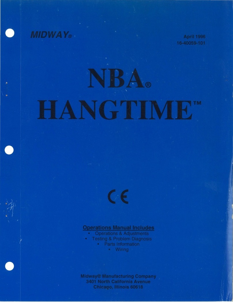
Midway NBA HANGTIME Series User manual

Midway

Midway NBA HANGTIME Series User manual

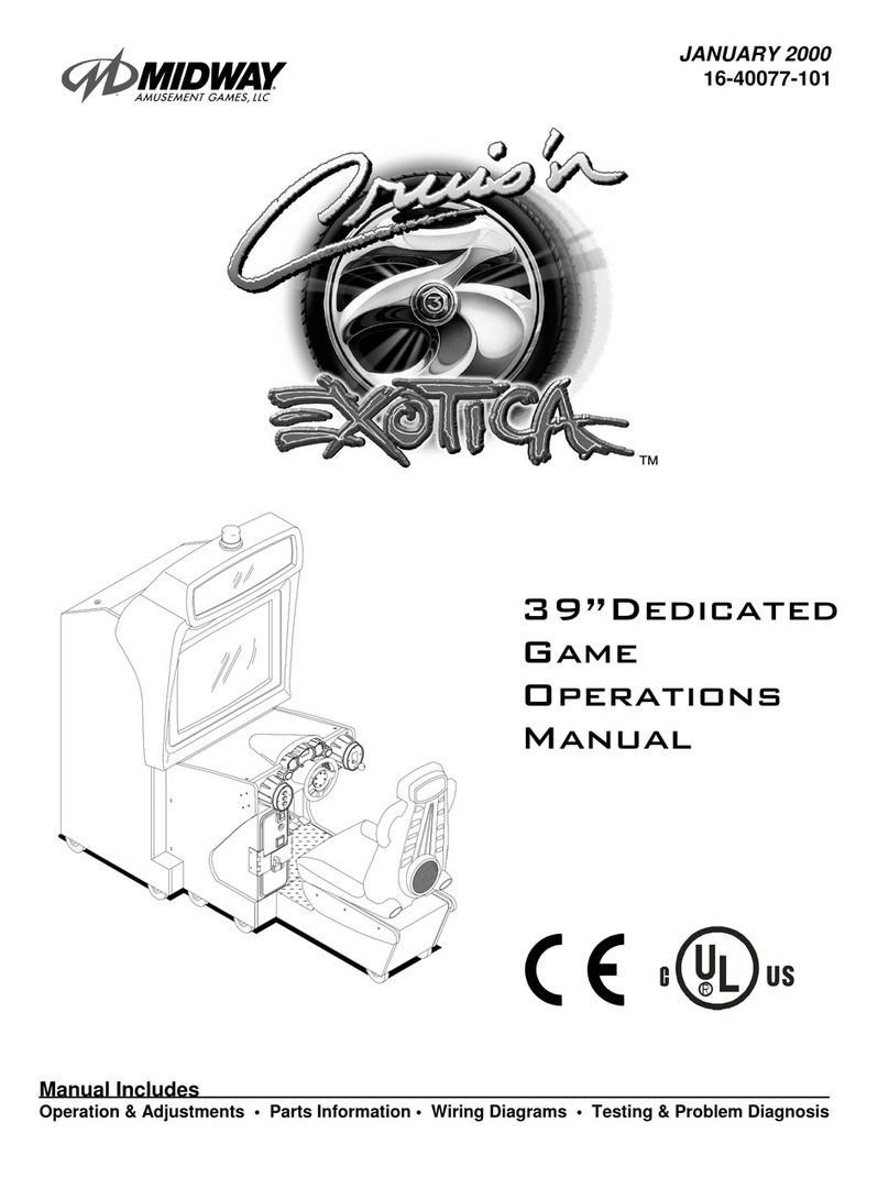
Midway CRUISIN EXOTICA 27" VIDEO User manual

Midway

Midway CRUISIN EXOTICA 27" VIDEO User manual

Midway Gauntlet Dark Legacy User manual

Midway

Midway Gauntlet Dark Legacy User manual

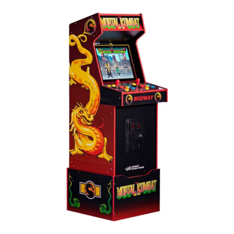
Midway Mortal Kombat User manual

Midway

Midway Mortal Kombat User manual

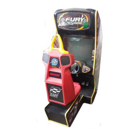
Midway CART Fury Championship Racing User manual

Midway

Midway CART Fury Championship Racing User manual

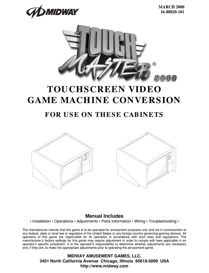
Midway TOUCH MASTER 8000 User manual

Midway

Midway TOUCH MASTER 8000 User manual

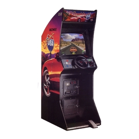
Midway CRUIS'N USA User manual

Midway

Midway CRUIS'N USA User manual

Midway Blitz User manual

Midway

Midway Blitz User manual

Midway TERMINATOR 2 JUDGMENT DAY Installation and operating instructions

Midway

Midway TERMINATOR 2 JUDGMENT DAY Installation and operating instructions

Midway Offroad Thunder User manual

Midway

Midway Offroad Thunder User manual

Midway Skins Game User manual

Midway

Midway Skins Game User manual

Midway BLITZ 99 Assembly instructions

Midway

Midway BLITZ 99 Assembly instructions

Midway Gauntlet Dark Legacy User manual

Midway

Midway Gauntlet Dark Legacy User manual

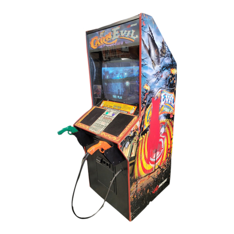
Midway CarnEvil User manual

Midway

Midway CarnEvil User manual

Midway Cruis'n Exotica User manual

Midway

Midway Cruis'n Exotica User manual

Popular Arcade Game Machine manuals by other brands

UNIS Extreme Shot Operation manual

UNIS

UNIS Extreme Shot Operation manual

Williams PIN-BOT instruction manual

Williams

Williams PIN-BOT instruction manual

BMI Gaming NICKTOONS nitro Service manual

BMI Gaming

BMI Gaming NICKTOONS nitro Service manual

Bandai Namco Tokyo Revengers Tamagotchi instruction manual

Bandai Namco

Bandai Namco Tokyo Revengers Tamagotchi instruction manual

Klarfit Spin manual

Klarfit

Klarfit Spin manual

Sega The Maze of the Kings Service manual

Sega

Sega The Maze of the Kings Service manual

Ice MONOPOLY ROLL-N-GO manual

Ice

Ice MONOPOLY ROLL-N-GO manual

Stern Pinball STAR WARS Pin Series Setup guide

Stern Pinball

Stern Pinball STAR WARS Pin Series Setup guide

MecPower Tecway Cyclontron Operation manual

MecPower Tecway

MecPower Tecway Cyclontron Operation manual

EXIDY CRASH installation instructions

EXIDY

EXIDY CRASH installation instructions

AINSWORTH A560X-ST Service manual

AINSWORTH

AINSWORTH A560X-ST Service manual

Icegame ROUND-UP Owner's and service manual

Icegame

Icegame ROUND-UP Owner's and service manual

Kriss Sport Superpunch BOXER user guide

Kriss Sport

Kriss Sport Superpunch BOXER user guide

Bay-Tek AXE MASTER Service manual

Bay-Tek

Bay-Tek AXE MASTER Service manual

Chicago Gaming REDLINE GT manual

Chicago Gaming

Chicago Gaming REDLINE GT manual

GCE Vectrex Spike manual

GCE

GCE Vectrex Spike manual

NAMCO Ridge Racer 2 Operator's manual

NAMCO

NAMCO Ridge Racer 2 Operator's manual

ELAUT Mistral manual

ELAUT

ELAUT Mistral manual

manuals.online logo
manuals.online logoBrands
  • About & Mission
  • Contact us
  • Privacy Policy
  • Terms and Conditions

Copyright 2025 Manuals.Online. All Rights Reserved.