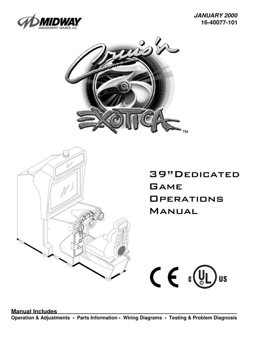
Midway CRUISIN EXOTICA 27" VIDEO User manual

@
C@~~~DWAY’
AMUSEMENT GAMES, LLC’
JANUARY 2000
16-40072-l 01
27”DEDICATED
GAME
OPERATIONS
MANUAL
0
Manual Includes
Operation &Adjustments l Parts Information l Wiring Diagrams l Testing
&
Problem Diagnosis

DECLARATION OF CONFORMITY
MIDWAY A&IUfijEMENT GAMES, LLC
3401 N.
CALlFORNIA
AVE.
CHICAGO, IL 60618
U.S.A.
WE, HEREBY DECLARE UNDER SOLE RESPONSIBILITY THAT
THE MODEL:
‘CRUISIN’EXOTJCA
27”
V1DE0’40272,40372.40472,40772,
40972,4,“72.41172,
41272, 41372. 41472, 41872, 42072, 42172, 42272, 42372, 4,172, 47272
TO WHICH THIS DECLARATION RELATES IS IN CONFORMITY WITH THE
FOLLOWING EUROPEAN PRODUCT SAFETY DIRECTIVES:
ELECTROMAGNETIC COMPATIBILITY DIRECTIVE
(89/336/EEC AND AMENDMENTS 9UC162/08, 92/31/EEC,93/68/EEC)
NT DESIGNED FOR US
(73/336/EEC AND AMENDMENTS
88K168102,
92/C210/01,
93/68/EEC,94/C199/03, 95/C214/02)
AS IS VERIFIED 6Y COMPLIANCE WITH THE POLLOWINQ STANDARD=
Date issued: JANUARY
24,ZCIOO
CORPORATE V.P. OF QUALITY

7.
a.
9.
10.
11.
12.
13
14.
Switch on power and closely observe the screen for each cabinet
durrng
start up. Each automatically enters
ATTRACT MODE
If
no errors are found. Refer to Troubieshoofing in the operatron manual if errors are detected.
Unlock the coin door for each cabmet to access the operator control buttons inside corn vault. Press and hold the
TEST button to enter the menu system.
i
Check the EPROM, GUTS, and MAIN information at the bottom of each game’s SELF TEST menu screen.
3Verrfy
linked games have compatible software
versrons.
Newer versions may contain
instructrons
prevrous
versrons do not, causing games to halt or reset at random
>Repeat this and all remaining steps for each linked cabinet.
Press the View 1 or View 2 button to select GAME OPTIONS. Press the ABORT button to activate this item.
Set the CABINET #; keeping in mind that each cabinet must have its own indrvidual and unique number. The
first cabrnet on the left is always cabtnet 1, the second is cabinet 2, etc.
Select NETWORK TESTS then press the ABORT button to activate it. Observe all linked cabrnets wrll be listed in
this screen. Refer to Menu System descriptions in the manual for more details.
Select CONTROLS TESTS. Follow on-screen instructions to confirm proper control operatron. Press and hold the
TEST button to reset steering wheel and pedal travel limits.
Select SOUND TESTS. Confirm operatron of all cabinet and seat speakers, and each amplifier.
Select MONITOR TESTS, Perform all tests and adjustments to ensure hrgh quality video.
Close and lock the coin door, and reinstall and lock the rear door for each cabrnet. Lower the leg levelers for
each cabinet untrl the casters do not touch the floor and the cabinets are level. Lock the levelers in positron by
trghtening the nuts provrded.

CRLIISN
EXDTICA
SECTION
ONE
.
,’,._---
.
-”
NOTICE:
This
manual is subject to change wlthout
notlce.
MIDWAY reserves
!he
v,ght
:L’
“-
:.-5
improvements in equipment
function,
design, or components as progress
8n
2’lgalec-;-
:
:.
manufacturing methods may warrant.
Flfl
out and mail in the lnformatlon Card
Include the Video Game Machine iVG!J
se’lat
ii..‘:<.
from the label on the rear of the
cabinet
For your records,
write
the
seu
n~.?oef
i
‘-3 /
manual.
I
SERIAL NUMBER
___
~__
__~

PRODUCT SPECIFICATIONS
Operating Requirements
Location Nectfical Power Temperature Humid@
Domes&c 1
ZOVAC
@
60Hz 4.0 Amps 32°F to 100°F Not to exceed 95%
relatrve
Foreign 230VAC
@
50Hz 2.0 Amps (0°C to 38°C)
Japan
1OOVAC
0
50Hz 4.0 Amps
Cabinet Statistics
Shipping Dimensions Shippina
Weiuht
(Approx.)
Desian Tvpe
Width 30” (76.2 cm) 350Lbs (158kg) Main Cabinet Sit-Down Dedrcated Video Game
Depth 64” (162.5 cm) 125Lbs (57kg) Seat Assy. Machine
wrth
Steering Wheel
Height 78” (198 cm) Feedback
Game Characteristics
P/aver Variables
Operator Variables
Diaqnostics
1 Player per VGM (Up to 4 with Linking) Coinage. Play Mode, Automatic Power-Up Self-Test
High Score Recognition
Difficulty, Volume,
Manual Multi-Level Menu System
AAMA Certified: Suitable for all Ages Audits, Statistics
Equipment Characteristics
Video Display Monitor
Medium Resolution RGB
27” (68.6 cm) CRT
Audio Svstem
Digltal Stereo
5” (12.7 cm) Coaxial Full Range
Speakers
Currency Acceptors
2 Coin Mechanisms
Dollar Bill Validator Ready
Electronic Coin Acceptor Ready
PRODUCT CONFIGURATION
+
Stand Alone Video Game Machine
Each VGM is ready to play right out of the box. Operators may use the menu screens
In
the game
menu system to determrne some player variables in advance or leave the choices up to the players.
+
Linked Video Game Machines
Linking allows players to compete against each other on a single course. Operator menus are used
the same way as in stand-alone VGMs. Crossover couplers and lrnking cables to connect two VGMs
are factory Installed. Use an optional 10 base-T ethernet hub to interconnect up to eight VGMs (two
groups of four).
Operations
-
4

SET-UP
Video Game Machine Array
1. inspect the exterior of the main cabinet and the seat pedestal for signs of damage prior to assembly.
.A
!WARNING
The cabrnet is top heavy. Do not push against plastic parts during movement.
2.
Remove the keys from the steering wheel. Unlock the coin, cash box, and rear doors to access the
electrical cords, mechanical components, and spare parts packed inside the cash box,
3.
Install one nut onto each leg leveler. Tilting as needed, locate the threaded holes under the cabinet
andpedestal, insert a leveler into each hole. Do not tighten nuts at
thus
time.
4.
Roll cabrnet to intended location, maintaining a clearance to work in, and lower each leveler until the
cabinet IS stable and level. Adjust levelers as necessary to equally drstribute the weight.
Ooeratrons
-
5

Location
bib,
w,
I_
“,
10‘
of Casters and Levelers
5
Reach inside the base of the cabinet and remove the bolts used to fasten a mounting rail to the
cabinet and set aside. Individually pull the rail out, flip it end for end, and reinsert it. Fasten the rari to
the inside of the cabinet with bolts until finger trght; some movement is required in the mounting rails
to align holes with pedestal assembly. Repeat for the mounting rail on the other side. See dragram for
proper placement.
Location of Pedestal Assembly Mounting Holes
Operations
-
6

6. Roll
the pedestal near the cabinet and align the opening in the pedestal
wrth
the ends of the
rails.
Slide the pedestal forward onto the rails leaving enough space to attach the wiring harness. Mate
each cable connector and press firmly to seat the contacts, Ensure no wires are pinched during
pedestal attachment. Fasten in place with the
‘/4
-20 tamper resrstant screws and large flat washers
provided in spare parts. Tighten the screws firmly
with
the wrench provided, and then tighten the bolts
for the mounting rails.
7.
Lower each leg leveler until the pedestal is stable and level
with
the cabinet. Adjust all levelers
until
both pieces are flush and parallel with each other. inspect for pinched wires, and then insert and
firmly
tighten the remaining fasteners to attach the two pieces as one.
8.
Remove the hasp used to secure the rear door from the spare parts bag. Remove the lock bracket
nuts from above the rear door opemng. Slide the hasp bracket onto the bolts until it protrudes through
the hole in the cabinet, and then reinstall nuts.
9.
Modify the lock plate by removing the hardware at the top of the rear door, rotating
It
so the slot
IS
above the door and rernstalling the nuts and bolts.
IO.
Reinstall the rear door onto the cabinet and lock it. If necessary, insert an extra padlock in the hasp at
this trme. install the screws at the top and sides of the rear door and tighten snugly.
11. Remove the power cord from the spare parts bag and insert a portjon of it
In
the cord clamp. Make
sure there is enough slack before plugging the cord into the receptacle.
Line Cord Installation
Operatrons
-
7

12. Plug the VGM into a grounded (3-terminal) AC wall outlet. Press the ON/OFF switch located near the
top of the cabinet to switch on power to the game cabinet. After the Self-Test Mode the game
automatically enters Attract Mode if no errors are found.
I
3. Open the coin door. Locate the operator control switch panel and then press and hold the Begin Test
button to enter the menu system. Wart until the Main Menu screen appears on the monitor.
Coin Door Switch Location
14. Follow on-screen instructions to select
Diagnostrcs,
then choose SWITCH TEST. Follow the
on-
screen instructions to verify that each of the controls is operational. If no errors are found, the controls
should function well.
15. Return to the Diagnostics screen. then choose MOTION TEST. Follow the on-screen rnstructlons to
verify that motion seat is operational. If no errors are found, the seat should function well.
16. Return to the Diagnostics screen, then choose SOUND BOARD TEST. Follow the on-screen
instructrons to verify that each of the speakers is operational. If no errors are found, the audio should
function well.
17. Return to the Diagnostics screen, then choose STEERING WHEEL TEST. Follow the on-screen
rnstructrons to verify the presence of steering resistance. If no errors are found, the aim will be good.
18. Return to the
Marn
Menu screen, then choose CALIBRATE CONTROLS Follow the on-screen
Instructions to set steering limits. If no errors are found. the controls will have the maximum
accuracy.
19. Return to the
Main
Menu screen, and then choose EXIT. The game will
automatrcally
enter
its
“attract” mode of operation (scenes and sounds from typical races, player’s scores, messages, etc.).
20. Insert currency or tokens and play a game. Change the volume and make any other adjustments.
Close and lock all open doors, Tighten the leveler nuts and engage the caster locks.
21. Insert currency or tokens and play a game. Change the
volurre
and make any other desired
adjustments. Close and lock
all
open doors. Make sure the leveler nuts are tightly fastened and
engage the caster locks.
Operations
-
8

0
a
MAINTENANCE
+
Viewing Glass
It is not necessary to switch off power to the VGM to clean the glass. Apply a mild glass cleaner to a
clean cloth or sponge and wipe the viewing glass. Do not apply the cieaner direct/y on the glass!
Liquid could drip down into
swatch
or control circuits and cause erratic game operation.
.Piayer Conirois
Use plastic-safe, non-abrasive cleaners to avoid damage. Apply cleaner to a clean cloth or sponge
and wrpe the ptayer controls. Do not apply the cleaner direct/y on the controls!
+
Cabinet and Seat
Use plastic-safe, non-abrasive cleaners to avoid damage. Apply cleaner to a clean cloth or sponge
and wipe the seat or cabinet. Do not apply cleaner directly on artwork or cabinef!
GAME FEATURES
CRUIS’N EXOTICArM ships configured for one-player game play. Cabinets may be linked to permit player
competitlon. A lighted header optlon is available.
Cruish ExoticarM is the
iatesf,
most thrilling and adventurous driving game in the Cruis’nrM v/de0 game
series. Piayers can seiect tracks iocated in near/y a dozen exotic locales around the globe. from Tibet
to
Atiantjs, Mars to Hong Kong, it is
evev
player’s goal to rack up h/gh scores and mIleage points.
Speeding on the/r way toward a first p/ace finish, drivers iisten
fo
cool tunes on the radio as they pass
palms swaying in the breeze, 3-Dimensional an/ma/s cavorting roadside, and a variety of shortcuts hidden
along the way. A p/aye& combined speed and
Sk///
vir?ua/ly
assure a place in the winner’s nrcle.
Player
/ncentives,
like free games for top speeds and distance, are sure to captivate players and ensure
many trips around the track. A player finishing in first p/ace soon discovers they have been whisked away
on a free trip to an exotic locale. (Player incentives are Operator Optional and enabled at the Operator’s
discretion)
For added exotement the dashboard now features a keypad. Player’s are encouraged to maintain a
personal access code and to use the keypad to recall piayer statistics. Player statistics record mileage,
win-to-loss ratio and high scores. As soon as the persona/ access code is entered, the stored player name
and /nformation is instantly recalled and displayed onscreen.
STARTING UP
Each
time
power IS swltched on or restored to the game machine, the system enters Start-up Tests. A
“rug” pattern appears on the CRT screen. When the “rug” pattern ends, the screen shows a CPU Board
map. Bad
ICs
are indicated in red, good
ICs
are
In
green. The software revision level IS shown at the top
of the screen.
A status screen to report on network activity will appear for about ten seconds. This screen IS used to
verify and troubleshoot connections on an array of cabinets.
The system enters Attract Mode once it passes all power-up tests. The Attract Mode screen will cycle
endlessly and drsplay a variety of scenes and sounds from a
typtcal
race on any given track. The system
does not exit Attract Mode until the desired amount of coins or tokens IS Inserted and game play
commence;.
NOTE: An error message appears on screen and the game does not enter start up if an error is detected
during the Start-Up Test, Record any messages before attempting to selvice the game.
Operations 9

GAME RULES AND OBJECTIVES
The game is configured for one-player game play, but up to four cabinets may be linked at one time to
promote multiple player competition. To enter Game Mode, individual player(s) must insert the required
amount of currency or tokens, press the Start button, and select a car and track. The main
objective
of the
game is to earn top ranking against other drivers.
PLAYER CONTROLS
Start button
The start button is used to begin game play or to select certain features before a race.
Radio button
The radio button allows the player to turn radio sounds on and off, and to change stations.
Lo button
This button shows the view from the driver’s seat inside the vehicle. This is a normal driver view.
Cam button
This button shows the view from directly above. The player can see the front end of the vehicle.
Hi button
This button shows an aerial view of the vehicle. This is what a helicopter camera would see.
Pedals
The gas and brake pedals control vehicle speed. Press the gas pedal twice to create a power boost.
Seat Position Adjuster
The seat position may be changed at any time, even during competition. Pull the adjustment lever to
the left while seated then slide the seat forward or backward. Release the lever to lock the seat into
position.
Ioerations
-

GAME OPERATION
Access to the menu system for statistics, adjustments, and testing is secured by a keyed lock to prevent
tampering. When the menu system is entered, on screen messages guide the operator through tasks.
Cabinet Switches
+
The ON/OFF SWITCH is located on the top side of the cabinet.
*
The REMOTE MONITOR ADJUSTMENTS are located inside the coin vault. Adjust video image size,
brightness. contrast, etc. using the Monitor Test screens and the monitor controls.
.
The SLAM TILT SWITCH detects forceful vibrations against the coin door to eliminate pounding for
free games, It is located on the inside of the coin door opening near the lock.
NOTE: The Slam switch is not present on Dollar Bill Validator (DBV) ready doors.
Control Buttons
+
The TEST BUTTON accesses the game Menu System. Press the Test button to access the Main
Menu and select Individual diagnostics, audits, utilities, etc.
t
The VOLUME UP BUTTON scrolls through menu selections or adjustment items and raises the
sound level in game play. An audible tone accompanies each activation of this button.
+
The VOLUME DOWN BUTTON scrolls through the menu selections or adjustment items and lowers
the sound level in game play. An audible tone accompanies each activation of this button.
t
The SERVICE CREDIT BUTTON allots credits without affecting the game’s bookkeeping total. This
button can also be used to exit from menu selectrons or to return to the main menu.
Coin Door Switch Location
Ooeratlons
-
11

CRUIS’N
EXOTICA
TM
SECTION
TWO
ADJUSTMENT, DIAGNOSTIC
SC
AUDIT
MENUS

MENU SYSTEM
WHAT IS THE MENU SYSTEM?
The game’s Menu System is a series of auditing, game adjustments and diagnostic screens. You can
easily access and apply these screens to optimize game performance. For instance..
3Use game audit screens to assess game performance.
>
Use adjustment screens to help you customize game performance. For example, you can restore
factory default game settings. You can also calibrate player controls for player accuracy.
3Use diagnostic screens to verify proper equipment operatron.
ACCESSING THE MENU SYSTEM
Open the coin door. Locate and press the TEST MODE switch. The game system will exit game Attract
Mode and enter Diagnostic Mode. The system runs a brief self-test, and then displays the Main Menu.
The Main Menu is the opening screen of the Menu System.
Game audits, adjustments and diagnostics are line items on the Main Menu. Selecting an item opens its
submenu. Every submenu presents various options that you may act upon.
MENU LAYOUT
Observe that each menu screen basically uses the same layout. The game ID, Serial Number, and Date
of Manufacture will appear on most of the menu screens, These numbers will be helpful to factory
personnel when referring to your game for parts or service.
pThe block at the top of each screen displays the current menu title.
3Data, such as menu items and video reports, etc., appears in the center of the screen.
i
Messages, for example explanations and active control functions, etc., appear at the bottom of the
screen.
MENU NAVIGATION TOOLS
Use the operator control buttons located Inside the coin door to navigate menus. Press the Volume Up or
Volume Down buttons to scroll through the menu options.
Notice the options sequentially become
highlighted. Press the Test button to select a highlighted option and access the next menu level. Press
the Service Credit button to exit from a menu option screen,
NOTE:
Only one highlighted option can be
selected at a time.
To return to play mode, press the Service Credit button while in the Main Menu screen
Diagnostics
-
2

Main Menu, continued
I/.
-:_:*
‘-
Diagnostic Menu
DIAGNOSTIC MENU
To verify the condition of the electrical and electronic hardware in the game, select DIAGNOSTIC MENU
at the Main Menu. Diagnostic tests assist you in checking and adjusting the game’s major systems. It is
important to periodically run diagnostics to improve and maintain game performance and player
satisfaction.
Use the Volume Up or Volume Down button to highlight the desired Diagnostic Menu option and press
the Test button to enter. Use the Service Credit button at any time to exit the Diagnostics and return to
the Main Menu.
NOTE:
The Burn-h Test cannot be halted from the menus.
Main Menu
_,L,.
.a
-
.-_
.:
,.I.,
.’
Diagnostic Menu, continued
Switch Test Menu
SWITCH TEST
To verify proper operation of switch and button inputs in the game, select SWITCH TEST at the Main
Menu.
Diagnostics
-
3

Use the Volume Up or Volume Down button to highlight the Switch Test option and press the Test button
to access it. Press any switch on the control panel or coin door to cause the corresponding indicator on
the screen to illuminate. Each illuminated square represents one completed switch circuit.
Main Menu
Diagnostic Menu, continued
Motion Test Menu
MOTION TEST
To verify functionality of motion seat controls, select MOTION TEST at the Main Menu.
Use the Volume Up or Volume Down button to highlight the Motion Test option and press the Test button
to access it. Use the Service Credit button at any time to exit the Motion Test and return to the Marn
Menu.
HOME POSITION.
The Home Position routine automatically centers the motion seat so that it is
positioned upright and does not tilt at any angle.
TILT LEFT.
The Tilt Left routine automatically tilts the motion seat at a left leaning angle.
TILT RIGHT.
The Tilt Right routine automatically tilts the motion seat at a right leaning angle.
TILT
FORWARD.
The Tilt Forward routine automatically tilts the motion seat at a forward leaning angle.
TILT BACK.
The Tilt Back routine automatically tilts the motion seat at a backward loaning angle
MULTIPLE COMMANDS.
The Multiple Commands routine automatically cycles through and performs
each of the other routines. Press the Service Credit button to stop the cycle and return to the Motion Test
Menu
r
Main Menu
Diagnostic Menu, continued
DIP Switch Test
DIP SWITCH TEST
,
To verify the functionality of both B-position DIP switches on the CPU Board, select DIP SWITCH TEST at
the Main Menu. Observe immediate on-screen results by changing the setting on a switch.
Use the Volume Up or Volume Down button to highlight the DIP Switch Test option and press the Test
button to access it. The current settings appear on-screen. Consult the table on the next page to
determine if changes are required. The default switch positions are all OFF for standard operation.
A vertical bar next to the switch position column indicates a common switch function
Diagnostics 4

DIP SWITCH TEST
Function SW1
SW2
SW3 SW4 SW5 SW6 SW7 SW6
Dedicated
*
OFF
Kit ON
!
Motion Disabled OFF
Link Disabled
Link Enabled
Linking I.D. Number
Master (Game Number
I)
Slave (Game Number 2)
Slave (Game Number 3)
Slave (Game Number 4)
Motion Enabled
1ON !/
Stand Up Style Cabinet
IOFF II
Sit Down Style Cabinet ON
Wheel Invert Disabled
OFF
Wheel Invert Enabled ON
Unused
i--l-
OFF
ON
I I
L
Setting
Table
II
t
for DIP Switch
OFF
ON
*
DIP
1,
Switch 1
&
be set to the OFF position in order for proper operation.
Game Adjustments for Linked Operation
To avoid confuslon, we recommend that all adjustments be set to identical values before Video Game
Machines
(VGMs)
are linked.
VGMs
might operate incorrectly if this is not the case, with the following
exceptions:
NOTE: All cabinets must have compatible software in order to link properly. Unlock the coin door and
press the 17ST button. The software version number is found on the Main Menu screen in game
diagnostics. It does not matter what version is installed as long as all version numbers are the same.
1. Linked
VGMs
must all have compatible software versions. Newer versions may contain
instructions that previous versions do not have, causing them to halt or reset at random.
On-Screen
messages will indicate that different versions are in use when the linking feature is enabled for each.
Diagnostics
-
5

The graphic effects and added attractions for the slave cabinets must be the same as the
master. All games must have these features enabled or all must have them disabled.
Mrxed
settings, for example road kill or a show girls setting, can cause games to become unsynchronized
during competition and lead to incorrect final results (i.e., two first place finishes with drfferent times,
collisions with unseen objects, etc.).
The linking feature overrides some of the individual software settings.
For instance, the master
(VGM
#l)
sets and controls the difficulty level for all linked slaves The difficulty level reported by the
slave games may not match the setting of the master game.
The linked game with the highest ranking determines software settings. Adjustments such as
bonus times will be controlled by the games in decreasing identification order. For example,
If
four
games are linked, slave game #3 will always override game #4 but have no effect on games #I or #2.
Thus permits games to have different standards to help equalize players with different skill levels.
The linking cables attach to a connector on a metal bracket located under the CPU Board
Assembly at the rear of the cabinet. Unlock and remove the cabinet rear door for linking
access.
Notes on Linking:
1.
For a g-way link, the leftmost VGM is the master
(#l);
the second VGM is slave #2. One linking cable
is required.
For a
3-way
link, the left VGM is the master (#l); the center and right
VGMs
are slaves
ti2
and
#3.
Two cables are required.
For a
4-way
link, the leftmost VGM is the master (#I); the left center VGM is slave
#2,
right center
machine is #3, and the right most machine is slave
M.
Three linking cables are required.
2. The linking feature will not function if the master is not turned on and in normal game play mode. If
the master is turned off, disconnected from the linking cable, or in any other mode of operation
(offlrne, diagnostics, etc.), none of the slaves will be able to link.
The linking feature will function for all other VGMs if one of the slaves is not turned on and in normal
game play mode. If any slave is turned off, drsconnected from the linking cable, or in any other mode
of operation (offline, diagnostics, etc.), the linking ability of other slaves will not be affected.
The linking feature will function for some VGMs, and not others, if all of the link activity switches are
not enabled or the software version numbers are not the same. The master game will not recognize
other games with disabled linking or different link identification numbers.
DIP SWITCH SElTlNG FOR COINAGE
There are many ways to select the type and quantity of currency recognized by the game machine.
1,
The most common coin combinations for several countries are pre-programmed and may be selected
from the table when Standard Pricing is activated (see Game Adjustments).
2. DIP Switch settings may be changed with the power switched on. Set any switch and then observe
the screen to verify that the desired selection is enabled.
NOTE:
If CMOS Coin Settings are active,
switch settings for an individual Country will have no effect.
3. Some European countries may accept currency used in other countries. The most popular coinage
settings are lrsted beneath ‘Other’ in the Standard Pricing Table.
4. Alternate settings are listed beneath ‘General’ in the Standard Pricrng Table.
5. Default settings are denoted by an
(‘).
Switches 1 through 5 select country codes. Switches 6 and
7
are used to select one of four modes for each country.
Dragnostics
6

-L-m.,.,,.,
a..
-,
,
_.
-.. -.
-,.
i4IINGARV 1
ON
1OFF /
ON
1OFF 1
ON
i..-..-
.
.
.
GENERAL I I
Iori I /-- I
ON 1ON 1OFF ION/i I
Table
for DIP Switch 2
Diagnostics
-
7

Main Menu
Diagnostic Menu, continued
CPU Board Test
t;
..-
CPU BOARD TEST
To
verify
proper operation of the memory circuits, select CPU Board Test at the Main Menu. This test
checks the memory circuits in a manner similar to the Start-Up Test. A “rug” pattern representing the
layout of the RAM and ROM circuits on the CPU Board
WIII
appear on-screen while the video circuits are
tested.
r-
__I_________
____
Use the Volume Up or Volume Down buttons to highlight CPU Board Test and press the Test button.
The memory circuits are shown as gray with a white outline. During the test,
KS
are good if they turn
green; they are faulty if they turn red. The game automatically returns to the Diagnostic Menu after the
test is completed.
Main Menu
Diagnostic Menu, continued
Sound Board Test
SOUND BOARD TEST
To verify proper operation of the sound components, select Sound Board Test at the Main Menu. This
test allows you to access and listen to the sounds used in the game.
ITEST
Use the Volume Up or Volume Down button to highlight the Sound Board Test option and press the Test
button. Press Service Credit to return to the Diagnostic Menu when finished.
Diagnostics
-
8
This manual suits for next models
16
Table of contents
Other Midway Arcade Game Machine manuals
Midway
Midway TOUCH MASTER 8000 User manual
Midway
Midway TERMINATOR 2 JUDGMENT DAY Installation and operating instructions
Midway
Midway 3A948 User manual
Midway
Midway Gauntlet Dark Legacy User manual
Midway
Midway Skins Game User manual
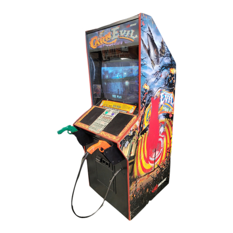
Midway
Midway CarnEvil User manual
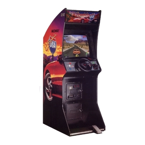
Midway
Midway CRUIS'N USA User manual

Midway
Midway BLITZ 99 Assembly instructions

Midway
Midway Gauntlet Dark Legacy User manual

Midway
Midway Blitz User manual
