Mighty Seven PB-1310 User manual

1
1. The maximum recommended air pressure during operation must not exceed 90 psi
(6.3bar). Higher air pressure may create unsafe operating conditions for the tool and
the user.
2. The compressed air should be cooled and have a water lter installed at the outlet
end of the compressor. Even with a water filter installed, some water may still
condense in the piping or hose and will enter the tool mechanism causing premature
damage to the tool. Therefore, it is recommended to install an air filter-lubricator
device somewhere between the tool and the compressor.
3. Always use an air compressor of the proper capacity to operate each tool.
4. Clean the hose with a blast of compressed air before connecting the hose to the air
tool. This will prevent both moisture and dust inside the hose from entering the tool
and causing possible rust or malfunction.
1. Using these tools in any potentially explosive environment is strictly prohibited.
2. It is always recommended that these types of tools must be operated when standing
on a solid or rm location.
3. Always use these tools in a well ventilated area.
4. Slipping, stumbling and falling are the major causes of potential serious injury,
therefore, a clean and clutter free surface in the working area before operating the
tools is strongly recommended.
Read this manual carefully before installing, operating,
servicing or repairing.
Working environment:
Air supply and connection requirements:

2
Ideal system connection:
Piping diameters and length requirement:
The diameter ΦA required for the inlet pipe is recommended on the specication table.
The diameter ΦB required for the branch pipe (from to ) should be 2 times as large as ΦA. ΦB
= 2 x ΦA
The diameter ΦC required for the primary air supply (from to ) should be 3 times as large as ΦA.
ΦC = 3 x ΦA
The length for the inlet pipe should be less than 15 feet (4.5m).

3
1. This tool should only be used as a hand operated tool. It is powered by compressed air and is not
insulated against electric shock.
2. This tool is specially designed for riveting sheet metals together. Any application or use of this tool other
than what it is designed for is strictly prohibited.
3. High sound levels may cause hearing damage. Always wear hearing protection when operating this tool.
4. Wearing eye/face protection can reduce the danger of high-speed materials being ejected from tool use.
5. User must wear proper clothing. Loose clothing, long hair, stings, straps, belts and jewelry should not be
worn when operating this tool.
6. Make sure that the all the specications of the rivets to be used are compatible with this tool.
7. Check the protection against the ejecting of rivet stem in place and is operative.
8. Make certain to stand on a solid or rm location and keep body in well-balanced position while operating
this tool.
9. Always turn off the air supply and disconnect the air hose before changing rivet nose or making
adjustments on this tool.
10.Release the throttle lever to avoid danger if there is a failure of energy supply or when connecting or
disconnecting the air hose.
11.Prolonged use will cause user fatigue. Periodic breaks are recommended for user safety.
12.It is recommended to stop operating the tool whenever the user experiences discomfort, tingling or pain
during use.
13.Beware if the compressed air hose breaks unexpectedly, or is being connected or disconnected
improperly. This whipping action may cause injury.
Warning:

4
1.Riveter case
2.Hanging ring
3.Riveter nose piece
4.Hex driver
----------1PCS
--------1PCS
--2SET
------------2PCS
Parts Description

5
All Parts Function Illustration
Hanging Ring
Riveter nose piece
Forward trigger (Rivet)
Reverse trigger(Rivet)
Exhaust Silencer
Air pressure regulator

6
Installation
Step 1: Install the part 4Put
the Hex driver in the middle of
the axis.
Note: The Hex connector
hole should be aligned with
the spindle.
Step 2: Install the part 3The
riveter nose piece.
Note: After the insertion of
the Hex driver, it should be
perfectly aligned with the rivet
head.
4
3

7
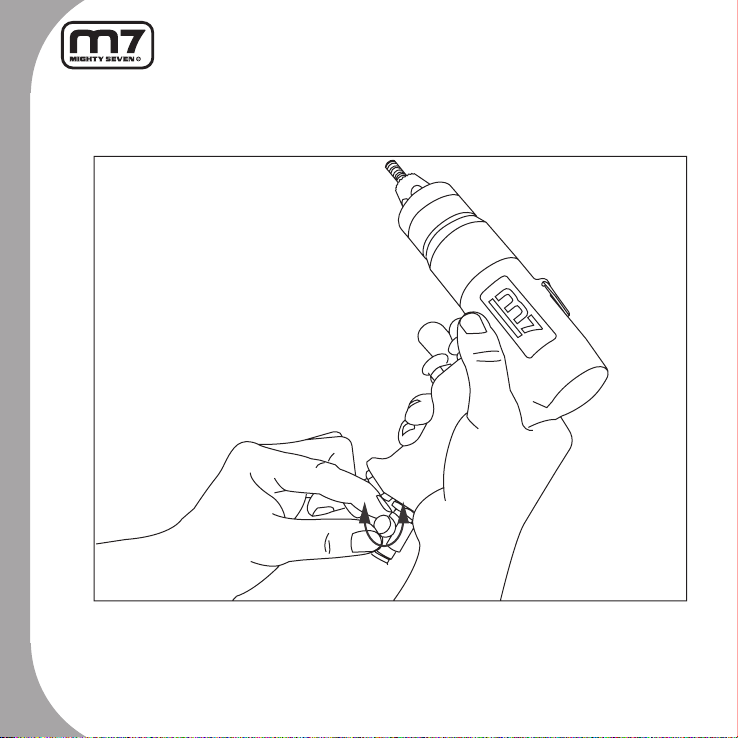
Step 3: Push down the
outside collar of the chuck
and insert the mandrel head.
Note: That it is installed
properly there will be a small
sound of the parts clicking
together.
Step 4: Before using, please
verify and check the correct
operation and installation of
the parts.
8
Step 5: When air pressure exceeds 90PSI (6.3BAR), please adjust the pressure valve to the
recommended operating level to avoid any problem.
The use of over pressure will reduce the lifetime of the tool and may cause injury to the user.
Note: Please refer to our specications for the suggested pressure values.

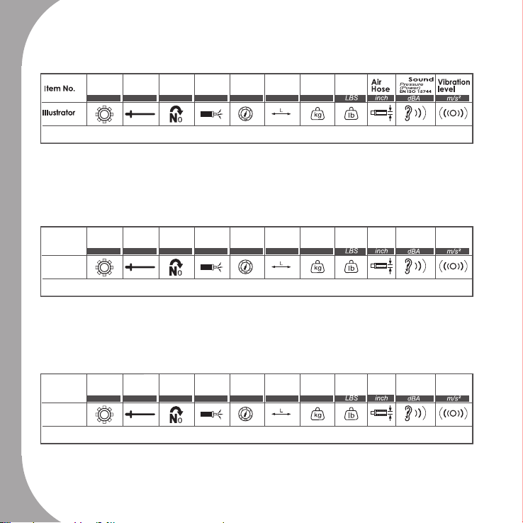
9
Gear M8~M10 400 7.8 90(6.3) ------ 1.74 2.79 3/8" 86.0 1.6
Gear M8~M10 400 7.8 90(6.3) ------ 1.74 2.79 3/8" 86.0 1.6
Gear M8~M10 400 7.8 90(6.3) ------ 1.74 2.79 3/8" 86.0 1.6
PB-1310
PB-1310
PB-1310
Free
Speed
Free
Speed
Free
Speed
Capacity
Capacité
Capacity
Structure
Structure
Structure
Ave. Air
Consumption
Cons. D'air
moyenne
Ave. Air
Consumption
Air
Pressure
Pression
Air
Pressure
Overall
Length
Net
Weight
Poids
Nettogewicht
Net
Weight
Poids Tuyau
d'air
Empf.
Luftschlauch
Niveau
sonore
Schalldruckpegel
Niveau de
vibration
Vibrationsniveau
Nettogewicht
R.P.M
R.P.M
R.P.M
mm
mm
mm
CFM
CFM
CFM
PSI(bar)
PSI(bar)
PSI(bar)
mm(Inch)
mm(Inch)
mm(Inch)
kg
kg
kg
Uncertainty K=0.5a if a≤5 m/s² or K=0.4a if a>5 m/s²
Uncertainty K=0.5a if a≤5 m/s² or K=0.4a if a>5 m/s²
Uncertainty K=0.5a if a≤5 m/s² or K=0.4a if a>5 m/s²
Longueur
Référence
Artikel-Nr.
10
Gear M8~M10 400 7.8 90(6.3) ------ 1.74 2.79 3/8" 86.0 1.6
Gear M8~M10 400 7.8 90(6.3) ------ 1.74 2.79 3/8" 86.0 1.6
Gear M8~M10 400 7.8 90(6.3) ------ 1.74 2.79 3/8" 86.0 1.6
PB-1310
PB-1310
PB-1310
Free
Speed
Free
Speed
Free
Speed
Capacity
Capacité
Capacity
Structure
Structure
Structure
Ave. Air
Consumption
Cons. D'air
moyenne
Ave. Air
Consumption
Air
Pressure
Pression
Air
Pressure
Overall
Length
Net
Weight
Poids
Nettogewicht
Net
Weight
Poids Tuyau
d'air
Empf.
Luftschlauch
Niveau
sonore
Schalldruckpegel
Niveau de
vibration
Vibrationsniveau
Nettogewicht
R.P.M
R.P.M
R.P.M
mm
mm
mm
CFM
CFM
CFM
PSI(bar)
PSI(bar)
PSI(bar)
mm(Inch)
mm(Inch)
mm(Inch)
kg
kg
kg
Uncertainty K=0.5a if a≤5 m/s² or K=0.4a if a>5 m/s²
Uncertainty K=0.5a if a≤5 m/s² or K=0.4a if a>5 m/s²
Uncertainty K=0.5a if a≤5 m/s² or K=0.4a if a>5 m/s²
Longueur
Référence
Artikel-Nr.

11
EC DECLARATION OF CONFORMITY
Original Language
Serial Number: Please refer to the tool
Air Hydraulic Riveters
Item No.: PB-1310
6.3 bar (90. psi)
relevant provisions of (MD) Machinery Directive 2006/42/EC and its amendment and
is manufactured and tested according to the following standards:
EN ISO 11148-1 / EN ISO 15744 / EN ISO 20643+A1
Declared in: Taichung, Taiwan
Dated:2013/06/01
Jonney Chen
Declared by: QA Manager
Signature
Manufacturer:
Mighty S even I nternational C o., Ltd.
No. 70-25, C hing Quang Rd., W ujih D ist.,
Taichung C ity, 4 1466 T aiwan
http://www.mighty-seven.com
A
uthorized c ontact t o compile the technical f ile:
King T ony France
3 Rue des imprimeurs Z I République Nord 1 .
86000 POITIERS F RANCE
TEL: ( +33)5-49-30-30-90
E-MAIL: christian.aubineau@kingtony.eu
12
Air Hydraulic Rivet Nut Toolr
ltem No.: PB-1310

13
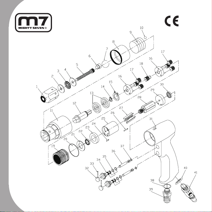
ltem No.: PB-1310
NO. PART NO. DESCRIPTION Q'TY
1 --- Nose Piece 1
2 --- Washer 1
3 --- Bearing 1
4 --- Washer 1
5 --- Screw 1
6 --- Ole Driver Hexagon 1
7 PB-1310P07 C-Shape Ring 1
8 PB-1310P08 Bit Sleeve 1
9 PB-1310P09 Sleeve Spring 1
10 PB-1310T10 Bit Lock Ball (3 pcs) 1 SET
11 PB-1310P11 Nose Housing 1
12 PB-1310P12 Bole Driver For Bearing 1
13 PB-1310T13 Bearing (2 pcs) 1 SET
14 PB-1310P14 C-Shape Ring 1
15 PB-1310P15 C-Shape Ring 1
16 PB-1310T16 Gear Cage (2 pcs) 1 SET
17 PB-1310T17 Planet Gear (6 pcs) 1 SET
18 PB-1310P18 Transmission Planet
Gear
1
19 PB-1310P19 Internal Gear 1
20 PB-1310P20 O-Ring 1
21 PB-1310P21 Washer 1
22 PB-1310P22 Bearing 1
NO. PART NO. DESCRIPTION Q'TY
23 PB-1310P23 Front End Plate 1
24 PB-1310P24 Pin 1
25 PB-1310P25 Cylinder 1
26 PB-1310P26 Pin 1
27 PB-1310T27 Rotary Blade (5 pcs) 1 SET
28 PB-1310P28 Rotator 1
29 PB-1310P29 Rear End Plate 1
30 PB-1310P30 Bearing 1
31 PB-1310P31 Motor Case 1
32 PB-1310T32 Switch Lever (2 pcs) 1 SET
33 PB-1310T33 Pin (2 pcs) 1 SET
34 PB-1310T34 Air Inlet Switch (2 pcs) 1 SET
35 PB-1310T35 O-Ring (4 pcs) 1 SET
36 PB-1310T36 Air Valve (2 pcs) 1 SET
37 PB-1310T37 O-Ring (2 pcs) 1 SET
38 PB-1310P38 O-Ring 1
39 PB-1310P39 Silencer Case 1
40 PB-1310P40 O-Ring 1
41 PB-1310P41 Air Regulator 1
PB-1310T01 Nose Piece for M10
(1.2.3.4.5.6)
1 SET
PB-1310T02 Nose Piece for M8
(1.2.3.4.5.6)
1 SET
Table of contents
Other Mighty Seven Rivet Tools manuals


