Miller Edge RB-P-K10 User manual

INSTALLATION INSTRUCTIONS
RBand for Doors
MODEL: RB-P-K10, RB-TX10
www.milleredge.com info@milleredge.com 800-220-3343 1/5
WARNING
Read and understand all instructions before beginning installation. Disconnect power to motor and test upon completion.
Wireless products should be installed by qualified personnel to ensure the requirements herein have been met. Keep
these instructions with the installation. Always abide by local and national electrical code specifications when wiring
accessories to motor controls.
The Miller Edge RBand Monitored Wireless Door Edge System is intended to provide a wireless connection between a
monitored sensing edge and a motorized operator installed with a garage door or grille. RBand meets the UL 325
requirements for monitored devices and has been certified as a UL 325 Recognized Component. It is designed for use with
operators that comply with UL 325 using a Miller Edge 10K Sensing Edge. Consult your operator manual for detailed
instructions about connecting to the motor.
KIT CONTENTS
RBand Edge Transmitter (RB-TX10)
RBand Door Edge Receiver (RB-P-RX10)
(2) 3.6V AA lithium batteries*
(4) #6 pan head transmitter mounting screws
*Replacement 3.6V AA lithium batteries can be purchased at your
local electronics store or via Miller Edge.
REQUIRED
1/8” flat blade screwdriver
1/4” flat blade screwdriver
Miller Edge 10K (T2/blue band) Sensing Edge
RECOMMENDED
Multi-meter capable of reading 10KΩ
Mounting screws as required for receiver
I. RECEIVER INSTALLATION
1. Turn off power to the door operator.
2. Remove Receiver cover and mount the receiver base near the operator, where it will be in line of sight with the
transmitter for the entire range of travel [IMAGE 1].
3. Connect power (12-24 VAC/DC) to the terminals marked power, noting the +/- polarity. 24 VAC power can be
connected either way not polarity sensitive [IMAGE 2].
4. Connect both PE1 and PE2 to the photo-eye inputs on the operator. N/A is not used.
5. Replace the Receiver cover and turn on power to the operator. Note: it takes ~5 seconds for the Receiver to
initialize.
Note: RBand Door Edge Receiver is compatible with up to 3 RBand Transmitters.
IMAGE 1. Door Installation with RBand Transmitter & Receiver
RB-P_INST_20210720
RB-P-K10 RBand for Doors
www.milleredge.com info@milleredge.com 800-220-3343 2/5
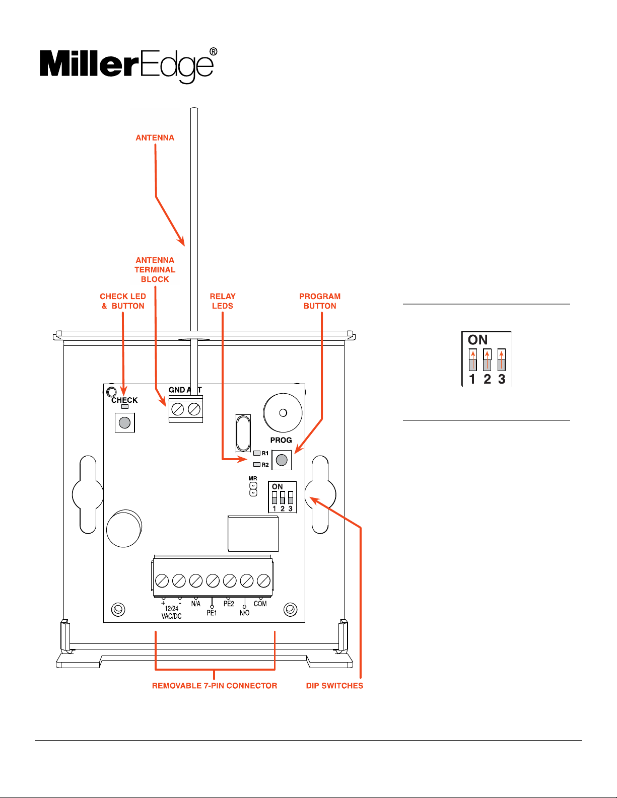
IMAGE 2. RBand Door Edge Receiver PCB & Connections
LED INDICATORS
Initial Power
No Transmitters Programmed: R1
LED on
R1 LED (1 edge connected)
Programmed: Off
Fault Condition: On
Check LED
Programmed: Check LED flashes
every 5 seconds
R2 LED
Not used
DIP SWITCH SETTINGS
Leave switches in factory default
settings (all on).
7-PIN CONNECTOR
+12/24 VAC/DC Constant power
source
-12/24 VAC/DC Constant power
source ground
N/A Not used
PE1 P.E. input
terminal
PE2 P.E. input
terminal
N/O Normally open
COM Relay common
RB-P-K10 RBand for Doors
www.milleredge.com info@milleredge.com 800-220-3343 3/5
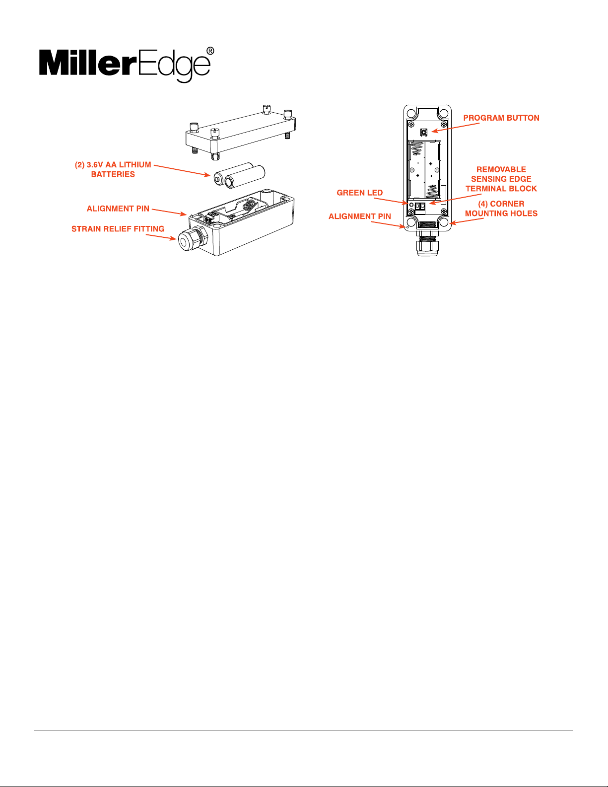
IMAGE 3. RBand Edge Transmitter PCB & Connections
II. TRANSMITTER: PROGRAM MODE
1. Confirm the Receiver is powered up. Prior to mounting the Transmitter, remove the cover and insert the batteries,
noting their polarity [IMAGE 3]. The green LED should blink to indicate that the Transmitter has not been
associated with the Receiver yet.
2. To enter learn mode, press and hold the Receiver program button [IMAGE 2] for ~2 seconds until the R1 LED
turns on, then release the button.
3. Press the Transmitter program button [IMAGE 3] for ~2 seconds. The Receiver should beep. Wait 10 seconds
for an additional beep to indicate that programming is complete.
4. Repeat 3-2 and 3-3 for up to 3 Transmitters.
III. TRANSMITTER: INSTALL & TEST
1. Strip back approximately 2 inches of outer covering of sensing edge cable, then feed through the Transmitter
strain relief fitting [IMAGE 3]. Connect the two sensing edge wires to the removable terminal. Dress the wires
with a small service loop and tighten the strain relief. Mount unit utilizing the mounting holes at the 4 corners of
the Transmitter box. Return lid to Transmitter, noting the alignment pin [IMAGE 3].
2. Test the sensing edge for functionality: press the sensing edge and the Receiver R1 LED will turn on.
IV. TROUBLESHOOTING
If the Receiver does not react to the Transmitter, you can check the RF signal strength:
1. Press the check button on the Receiver for ~2 seconds [IMAGE 2]; 4 beeps will be heard. You then will hear a
beep every 1-1/2 seconds during the check process. Wait about 30 seconds; if no other beeps occur, your
system is functioning. 3 quick beeps indicates a communication error.
2. Activate the sensing edge and observe the check LED; 3-5 flashes is ideal. Less than 3 flashes means there is a
weak signal.
3. To exit check function, press the check button again, or the system will time-out after 5 minutes. There will be a
series of beeps heard upon exiting.
V. ERASING THE RECEIVER
Erase the Receiver if you need to replace a Transmitter or you have any other programming problems:
1. Use a screwdriver to short the two pins next to the DIP switch marked MR [IMAGE 2].
2. While shorting the pins, press and hold the program button for several seconds; you will hear a series of 10
beeps following by a rapid chirping sound.
3. When the chirping stops, release the program button. Wait ~10 seconds and you will hear 2 beeps. The
Receiver is now ready to be reprogrammed.
VI. TECH SUPPORT
For additional assistance, contact Miller Edge Tech Support: 800-220-3343
VII. TRANSMITTER: SPECIFICATIONS & CONTROLS

RB-P-K10 RBand for Doors
www.milleredge.com info@milleredge.com 800-220-3343 4/5
Transmitter Frequency: 916 MHz, FSK modulation
TX Indicator Lights:
Green LED: Normally off
Press program button for status
Mounting: 4 corner screws (provided)
Power Source: Batteries: 2 AA, 3.6V lithium, 2 year life expectancy
Dimensions: 1.80”L x 4.78”W x 1.75”H
Program Button: Momentary push button is used to associate the Transmitter to the Receiver.
VIII. RECEIVER: SPECIFICATIONS & CONTROLS
Power: 12-24 VAC/DC nominal (11-30 V max); power may be supplied from the operator or alternatively from an
external supply. 100 mA maximum current draw.
Cable Connections: Screw clamp type terminal blocks for 18-26 AWG wire.
Dimensions: 4.12”L x 3.65”W x 1.65”H
Learn Button: Used to associate a Transmitter with the desired receiver channel.
Check Button: Press to determine the signal strength. 4 or 5 blinks is ideal.
RX Indicator Lights:
Check LED:
1. Blinks every ~5 seconds to indicate working properly
Channel LED:
1. Off when the associated sensing edge is learned and has no faults
2. On solid: No Transmitters learned or sensing edge is active
Connections:
Power (2)
Output:
1. PE1,PE2: Photo-eye style pulsed output
2. N/A; High speed pulse output (not commonly used)
3. COM,N/O: Normally Open output for non-monitored
applications
IX. FCC COMPLIANCE
Transmitter
Model: RB-TX10
FCC ID:
U5Z-RB-TX10
Receiver
Model: RB-P-RX10 FCC
ID: U5Z-RB-D-RX10
This device complies with Part 15 of the FCC rules. Operation is subject to the following two conditions:
1. This device may not cause harmful interference and
2. This device must accept any interference received, including interference that may cause undesired operation.
This equipment has been tested and found to comply with the limits for a Class B digital device, pursuant to Part 15 of
the FCC Rules:
These limits are designed to provide reasonable protection against harmful interference in a residential installation.
This equipment generates, uses and can radiate radio frequency energy and, if not installed and used in accordance
with the instructions, may cause harmful interference to radio communications. However, there is no guarantee that
interference will not occur in a particular installation. If this equipment does cause harmful interference to radio or
television reception, which may be determined by turning the equipment off and on, the user is encouraged to try to
correct the interference by one or more of the following measures:
1. Re-orient or relocate the receiver antenna
2. Increase the separation between the equipment and the receiver
3. Connect the equipment into an outlet on a circuit different from that to which the receiver is connected
4. Consult the dealer or an experienced radio/TV technician for help

RB-P-K10 RBand for Doors
www.milleredge.com info@milleredge.com 800-220-3343 5/5
Changes or modifications not expressly approved by the party responsible for compliance could void the user’s
authority to operate the equipment.
X. MAINTENANCE
It is strongly recommended that users check wireless systems at least once per month for low batteries alerts, and
damage to housings and mountings. Also check for signs of damage to sensing edge and cable connection points.
Compress the sensing edge 2” from both ends and in the center and observe that it sends an electric signal to the
controls. Refer to your operator manual for detailed instructions about motor connections.
XI. REPLACEMENT
To replace your Miller Edge wireless system, contact your sales representative. Attempting to repair your Miller Edge
wireless system is not recommended and will void the manufacturer warranty.
XII. WARRANTY
RBand for Doors (model: RB-P-K10) carries a 2-year warranty from date of shipment from Miller Edge for credit or
replacement. This warranty applies to normal use, which is found to have defective materials or workmanship, as
determined solely by an authorized factory representative. This warranty is void where evidence of misuse or abuse is
present. This warranty covers repair or replacement of the purchased product only; product installation/labor charges
are not covered. Miller Edge manufactures its products to meet stringent specifications and cannot assume
responsibility for those consequences arising from improper installation or misuse. Installation instructions and testing
procedures provided by Miller Edge must be followed for proper operation and maintenance.
XIII. ACCESSORIES
Contact your Miller Edge sales representative for accessories to wireless systems:
WARNING
LABELS
BATTERIES MOTION
SENSORS
MOUNTING
CHANNELS
MODULES
(MIM)
EDGE TESTER
This manual suits for next models
1
Table of contents
Other Miller Edge Gate Opener manuals


Popular Gate Opener manuals by other brands


Chamberlain
Chamberlain LiftMaster Professional SLY2500 Installation

Matikgate
Matikgate FLOW user manual

Platinum Access Systems
Platinum Access Systems ACTP715 Installation instruction and owenrs manual

Roger Technology
Roger Technology R20 Series user guide

GDS
GDS GDS 4 Installation and maintenance manual

Casanoov
Casanoov TANKER B700 manual

Hiland
Hiland SLG5280X user manual

Centurion
Centurion D5-EVO REPAIR Programming manual

Mirrow
Mirrow Moovo LN4 Series Installation and use instructions and warnings

Nice
Nice MhouseKit WU200S Instructions and warnings for installation and use

Cardin
Cardin BLTOW24 Series instruction manual

WORKMASTER
WORKMASTER GO-B3 Operator's guide