EN
8
•When Gate is Obstructed : Gate stops.
•Optional : The Gate Opener Controller can be connected to a solar system, a Flash light warning, a
photocell, back up battery, keypad and other access control devices.
•Speed Control : Gate opening and closing speed can be adjusted.
•Gentle Start : The Gate Opener is equipped with a soft start function.
•Auto Close : The Gate Opener System is equipped with Auto close function with adjustable closing
time delay.
•Single or Dual Gate : Either Single or Dual Swing Gate can be opened.
•Multiple Remote Transmitters : The Controller can easily accommodate several unique extra remotes
to control the swing gate opener.
•Battery Back Up : DC 24V back up battery can be incorporated
•Optional Devices : DC 24V Gate Lock, photocell ,keypad , photocell, push button, large size or small
size control box.
The Gate Opener can be configured to allow smooth noiseless operation.
The Gate Opener can be configured to enable open condition as default, or close condition as default
depending on the placement of the provided hardware brackets.
General options and accessories
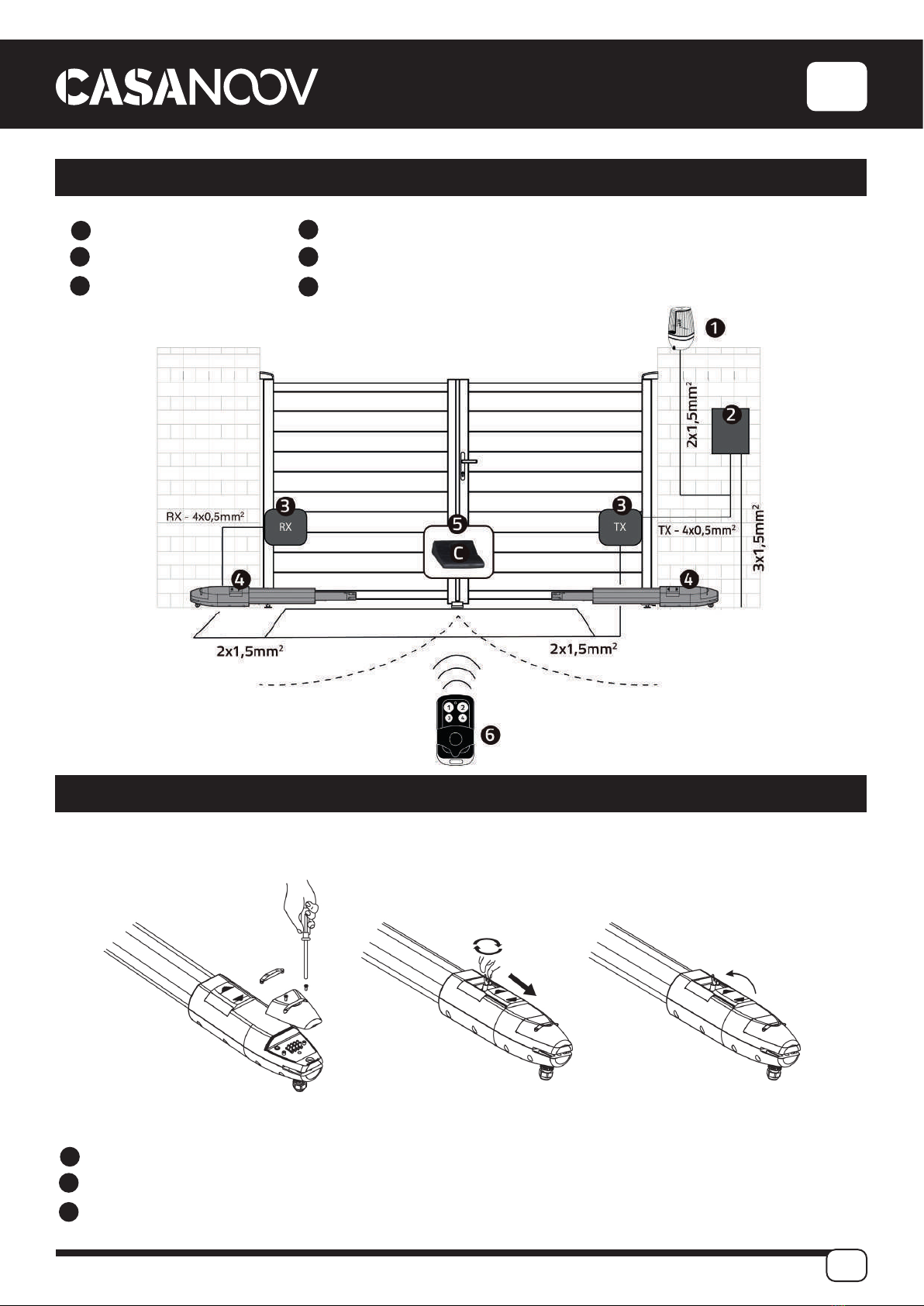
Primary Post Bracket
Secondary Post Bracket Clutch Key
Gate Bracket
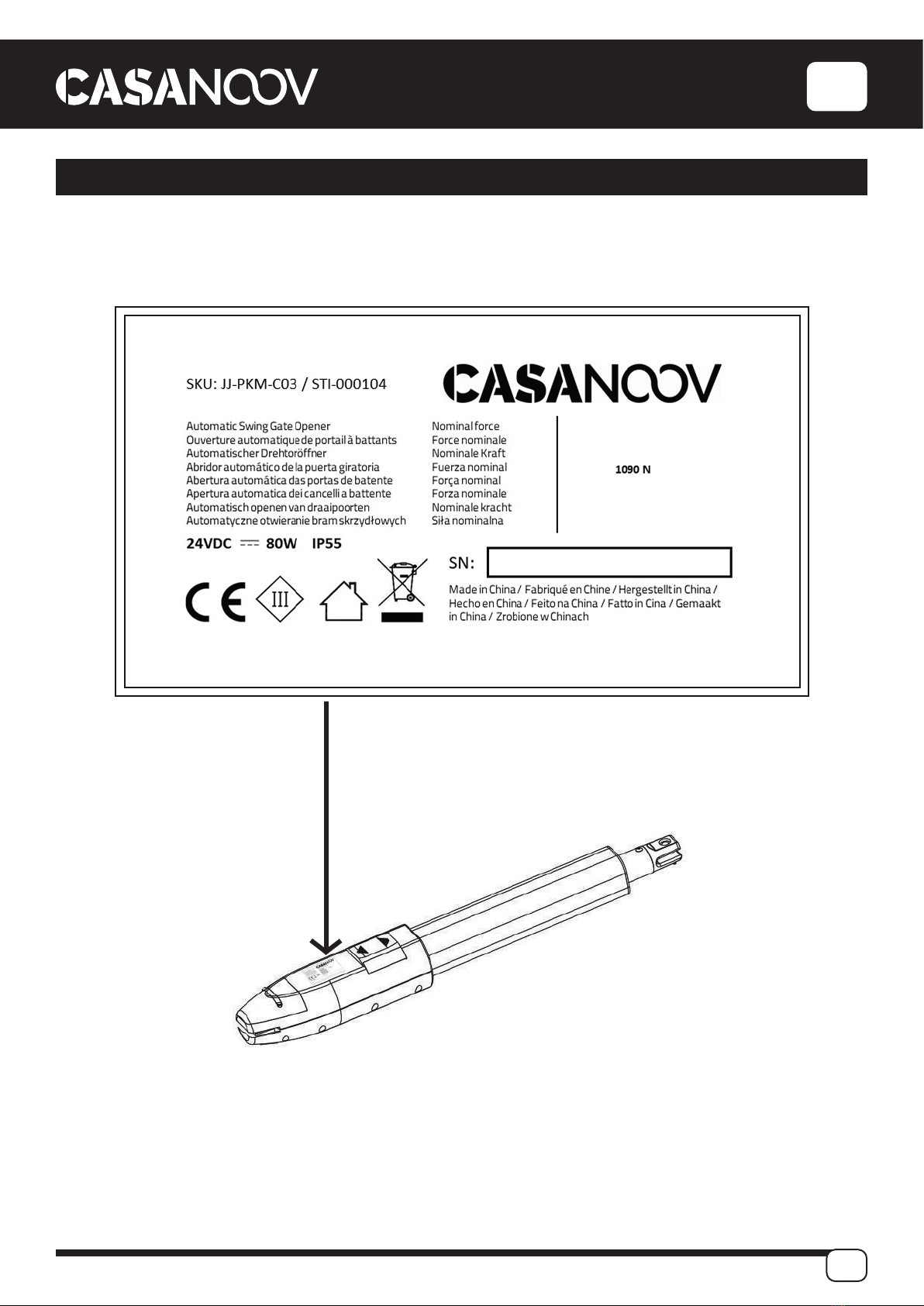
Motor
Actuator Arm