Megger MIT1020/2 User manual

-~
ARTISAN
®
~I
TECHNOLOGY
GROUP
Your definitive source
for
quality
pre-owned
equipment.
Artisan Technology
Group
Full-service,
independent
repair
center
with
experienced
engineers
and
technicians
on staff.
We
buy
your
excess,
underutilized,
and
idle
equipment
along
with
credit
for
buybacks
and
trade-ins
.
Custom
engineering
so
your
equipment
works
exactly as
you
specify.
•
Critical
and
expedited
services
•
Leasing
/
Rentals/
Demos
• In
stock/
Ready-to-ship
•
!TAR-certified
secure
asset
solutions
Expert
team
ITrust
guarantee
I
100%
satisfaction
All
tr
ademarks,
br
a
nd
names, a
nd
br
a
nd
s a
pp
earing here
in
are
th
e property of
th
e
ir
r
es
pecti
ve
ow
ner
s.
Find the Megger MIT1020/2 at our website: Click HERE

M
MIT1020/2
10kV Digital Insulation Tester
USER MANUAL

GSAFETY WARNINGS
Safety Warning must be observed during use.
nThe circuit under test must be switched off, de-energised, isolated and checked to be safe before insulation test connections are made. Make sure the
circuit is not re-energised whilst the instrument is connected.
nCircuit connections must not be touched during an insulation test.
nAfter completing a test, capacitive circuits must be completely discharged before disconnecting the test leads. Capacitive charges can be lethal.
nTested items should be firmly shorted out with a shorting link, after discharge, until required for use. This is to guard against any stored dielectric
absorption charge subsequently being released thereby raising the voltage to potentially dangerous levels.
nThe voltage indicator and automatic discharge features should be regarded as additional safety features and not a substitute for normal safe working
practice.
nIt is rare, but in certain circumstances, breakdown of the circuit under test may cause the instrument to terminate the test in an uncontrolled manner,
possibly causing a loss of display while the circuit remains energised. In this event, the unit must be turned off and the circuit discharged manually.
nTest leads, including crocodile clips, must be in good order, clean and with no broken or cracked insulation.
nThe instrument should not be used if any part of it is damaged.
nInsulation testing in wet weather conditions might be hazardous. It is recommeded that this instrument is not used in these circumstances. If this
unavoidable, the user must take all necessary precautions.
nThis instrument is not intrinsically safe and must not be used in hazardous atmospheres.
nIf this instrument is used in a manner not specified by the manufacturer, the protection provided by the equipment may be impaired.
2
NOTE
THE INSTRUMENT MUST ONLY BE USED BY SUITABLY TRAINED AND COMPETENT PERSONS.
Users of this equipment and/or their employers are reminded that National Health and Safety Legislation requires them to carry out valid risk assessments of
all electrical work so as to identify potential sources of electrical danger and risk of electrical injury such as inadvertent short circuits. Where the assessments
show that the risk is significant then the use of fused test leads may be appropriate.

Test mode summary 16
Insulation resistance ‘IR’ test 16
Breakdown mode / burn mode 16
Alarm limit mode 16
Step voltage ‘SV’ test 17
Polarisation index ‘PI’ test, and dielectric absorption
ratio ‘DAR’ test 17
Dielectric discharge ‘DD’ test 17
Measurements above 100 GΩ18
Circuit block diagram 19
Specifications 20
Accessories 21
Repair and warranty 22
Battery replacement 22
Symbols used on the instrument are:
F Caution: risk of electric shock
G Caution: refer to accompanying notes
t Equipment protected throughout by Double
Insulation (Class II)
c Equipment complies with current EU directives.
This equipment should be recyled as electronic
waste.
Terms used in this manual
The word must is used to indicate that the instructions following should
be followed under all circumstances. Failure to follow these instructions
could result in damage to the instrument and / or a hazard to the operator.
The word should is used to indicate that the instructions indicate best
practice.
CONTENTS
3
Safety warnings 2
Introduction 4
General description 4
Features 4
Cleaning 4
Power lead and battery charging 5
Instrument controls and indicators 6
Power On/Off button 7
Test voltage sand tbuttons 7
Test start / stop button 7
Ω/I button 7
Bbutton 10
Fn button 10
Mode button 10
Timer sand tbuttons 11
Record button 11
Recording to on-board memory 11
Downloading results 11
Deleting results 11
Recording to a PC 11
High voltage warning LED 12
Line input present LED 12
Test terminals 12
Guard terminal 12
RS232 / USB connections 12
Battery bar graph 13
Voltage at terminals 13
Timer indicator 13
Digital display 13
Analogue display 14
Secondary display 14
Pre-Test / during test key action table 14
Breakdown detection 15
Noise detection 15

Features
nContinuous resistance or current measurement on main display.
nOptional resistance, current, or figure of merit measurements on
secondary display.
nStandard test voltages – 250 V, 500 V, 1 kV, 2.5 kV, 5 kV, 10 kV
nNon-standard test voltages – selectable between 50 V and 1 kV in 10 V
steps, and selectable between 1 kV and 10 kV in 25 V steps.
nTest modes include insulation resistance, polarisation index, step
voltage and dielectric discharge.
nThe dielectric absorption ratio is automatically calculated if the
corresponding timers are set.
nEither burn or breakdown selectable in insulation resistance mode.
nInsulation ‘Alarm Limit’ available in insulation resistance mode.
nProgrammable timers include a main test duration timer, plus T1 and
T2 timers for time resistance method type tests.
nLoad capacitance and time constant measurements – displayed at end
of test.
nLCD backlight.
nData storage, data retrieval and real time data output.
nUSB or RS232 communications.
nBattery level / charge level indicator.
Cleaning
Disconnect the instrument and wipe it with a clean cloth slightly damped
with soapy water or Isopropyl alcohol (IPA).
INTRODUCTION
4
General Description
The MIT1020/2 is a microprocessor controlled 10 kV insulation tester
offering measurement capability of up to 35 TΩ. The instrument performs
automatic tests and has data storage and data retrieval facilities.
Polarization index and dielectric discharge tests are performed
automatically, and test duration and voltages can be adjusted according
to user preference for these tests. A step voltage test can be performed
automatically, with a default voltage of 1 kV, and test duration of 5
minutes. It is possible for the user to set different voltages and test
durations for the step voltage test.
The MIT1020/2 can be powered from the mains supply or by its own
internal rechargeable battery, which provides for at least 4 hours of
continuous testing with a 100 MΩload. A battery level indicator on the
LCD display indicates battery capacity. Connecting power to the mains
supply connector will automatically charge the battery whether the
instrument is switched ‘on’ or ‘off’, except during testing. A high level
of internal isolation allows the instrument to be used while the unit is
supplied from the mains. An internal battery management system switches
the instrument off after ten minutes of inactivity. If the battery approaches
a very low state of charge the instrument turns itself off, and mains power
must be applied before the instrument can be used again. Recorded test
results and settings will not be lost when the instrument is switched off.
A comprehensive LCD display shows resistance, current, capacitance, time
constant, voltage, timer measurements, and figure of merit measurements
such as polarisation index.

POWER LEAD AND BATTERY CHARGING
5
If the power lead supplied is not suitable for your mains connection, do
not use an adaptor. Always use a power lead fitted with the correct plug.
The instrument is fitted with a two-pin IEC60320 power inlet. Most power
leads are made with three-core cable, so the ground connection will not
be used.
Power lead connection table
Connection UK/International USA
Earth/Ground Yellow/Green Green
Neutral Blue White
Live (Line) Brown Black
If using a fused plug, ensure that it is fitted with a 3 Amp fuse.
The instrument can be powered from 85 - 265 Vrms a.c. at 50/60 Hz. The
battery will charge as long as the mains supply is connected, except when
a test is in progress. The power On/Off button has a green LED, which
illuminates when mains power is present. For optimum battery life, charge
the battery after each use. A completely exhausted battery will take 14
hours to recharge.

INSTRUMENT CONTROLS AND INDICATORS
6
Measurement terminals
-ve guard +ve
RS232
USB
Line
input
Time s and
t selectors
Voltage s
t selectors Line input
Present
indicator
Power on/off
Ω/I selector
Burn indicator Alarm Data recording
Test modes
Voltage at
terminals
Battery level
Breakdown
indicator
High voltage
warning
indicator
High
voltage
warning
indicator
Analogue
display
Timers
Main, T1,
T2
Dielectric
absorption
ratio/T1 timer
Digital
display
Polarisation
index/timer T2
Time
constant
Capacitance
display
Data record
High voltage
warning indicator
Test start/stop
ModeFunction
Backlight
on/off

7
When the test has stopped, the display continues to show the voltage
present on the test leads. Pressing either test voltage sor tbutton will
then display the test voltage immediately before the end of the test.
Test start / stop button
A test will only start if this button is pressed, held and then released as
soon as the red high voltage warning indicator LED lights. The LCD and
red LED high voltage warning indicators flash when the test starts.
A test will not start if the button is released before the red LED shows, or
pressed continuously for longer than 5 seconds. This is a safety feature to
prevent a test being started inadvertently.
The presence of a voltage greater than 50 V on the test leads is indicated
with flashing high voltage warning indicators. Testing is disabled if the
external voltage exceeds 80 V.
Testing will stop if the test start / stop button is pressed again, the
preset test time is reached, or, if the unit is not in burn mode, insulation
breakdown is detected.
When a test has finished, the instrument will discharge the load, which
may take some time. The operator must always check the load has been
discharged before touching the test leads.
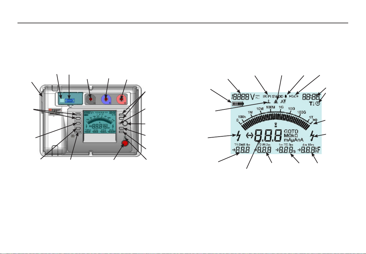
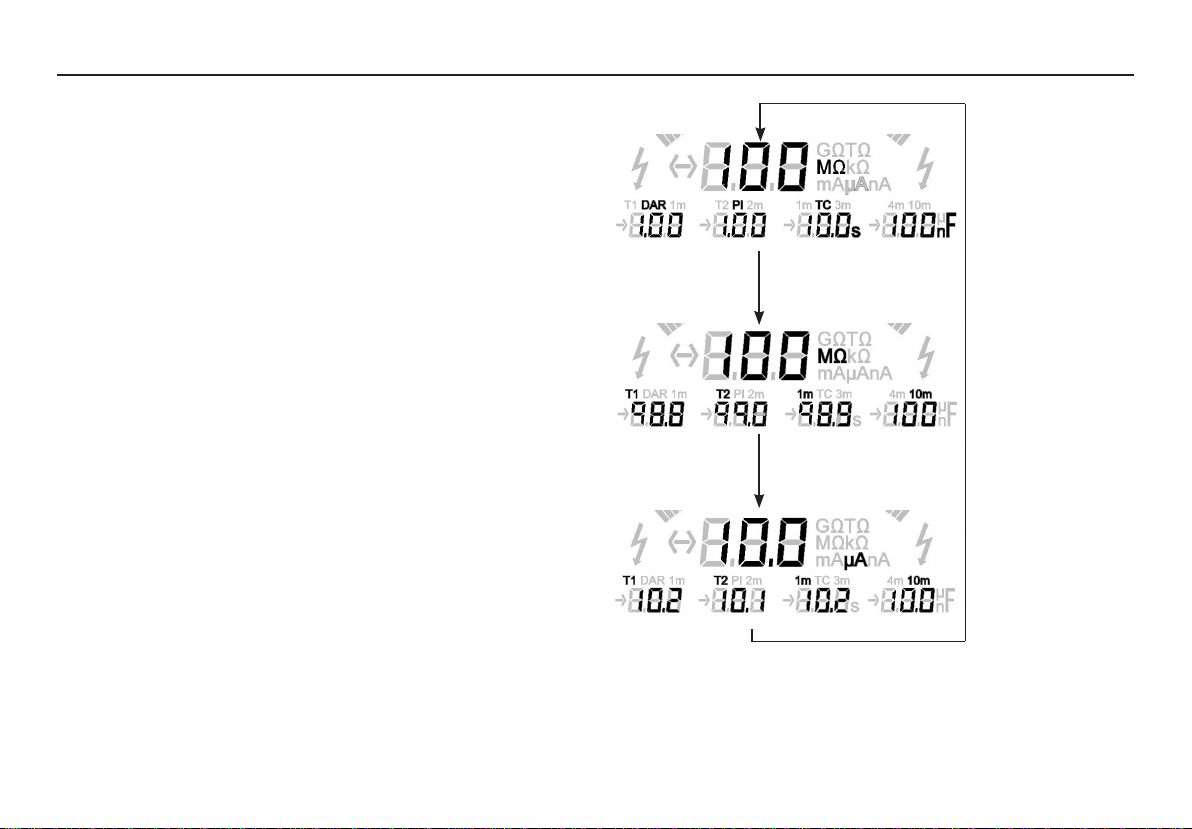
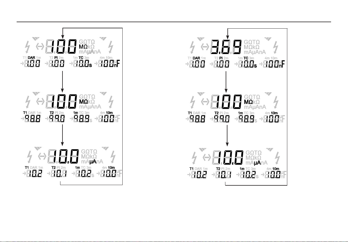
Ω/I button
Pressing this button toggles the digital and secondary displays. The details
available when scrolling the secondary display will depend upon the test
mode selected, whether timers T1 and T2 have been set, and the duration
of the test. The digital display toggles between insulation resistance and
current.
Power On/Off button
The instrument will only turn on if this button is pressed, held and then
released when the display responds. The instrument will not turn on if
the button is released before the display responds, or if the button is held
down for too long. This is a safety feature to prevent the instrument being
inadvertently turned on.
The instrument is turned off either by pressing the button again, or if the
instrument is running on the battery, by timing out after 10 minutes of
inactivity.
Upon switching the instrument on the display will first show ‘Ini’ while it
undergoes a self-checking routine. When Ini disappears, the instrument is
ready for use.
Test voltage sand tbuttons
Using these buttons one of six test voltages can be selected: 250 V, 500 V,
1 kV, 2.5 kV, 5 kV, and 10 kV. The selected voltage is shown on the display.
A non standard voltage between 50 V and 10 kV can be selected by holding
down the ‘Fn’ function button whilst operating the buttons. The selectable
voltage is adjustable in 10 V steps between 50 V and 1 kV, and adjustable in
25 V steps between 1 kV and 10 kV. An auto repeat facility is enabled when
the button is held down, allowing faster travel through the range.
If there is an external voltage greater than 50 V on the test leads, the high
voltage warning indicators are flashed, and the display shows this voltage
instead. The instrument will not perform a test if this voltage is greater than
80 V.
During a test the display shows the actual voltage on the test leads. If the
test voltage is changed during a test, the new test voltage will be displayed
briefly.

8
Figure 1 - The result of an insulation resistance test (IR)
Test settings: T1 and T2 times set in order to measure the DAR
Test conditions: test runs for longer than 10 minutes as this is required for
a PI reading.
In the ‘IR’, ‘PI’, and ‘DD’ modes the secondary display initially shows the
PI (polarity index), DAR (dielectric absorption ratio), and, on completion
of the test, the TC (time constant) and capacitance measurements.
Toggling the display shows insulation resistances and currents.
In the ‘SV’ (step voltage) mode, the secondary display toggles between
insulation resistances and currents.
Figures 1 to 4 illustrate the display status for sequential ‘Ω/I’ key presses in
the different modes. Press Ω/I
Press Ω/I
Press Ω/I

Figure 3 - The result of a dielectric discharge test (DD)
Test settings: T1 and T2 times set in order to measure the DAR
Test condition: test runs for longer than 10 minutes as this is required for
a PI reading.
Figure 2 - The result of a polarity index test (PI)
Test settings: T1 and T2 times set in order to measure the DAR
Test conditions: timer defaults to 10 minutes, as this is required for a PI
reading
9
Press Ω/I
Press Ω/I
Press Ω/I
Press Ω/I
Press Ω/I
Press Ω/I

10
Button Press Function Comment
Fn + VsIncrement in 10 V steps Voltage range between
50 and 1000 V
Fn + VtDecrement in 10 V steps Voltage range between
50 and 1000 V
Fn + VsIncrement in 25 V steps Voltage range between
1000 and 10000 V
Fn + VtDecrement in 25 V steps Voltage range between
1000 and 10000 V
Fn + Ts or TtCycle through timers Select main timer, T1 or
T2
Fn + Mode Cycle through IR modes Select breakdown, burn
or alarm limit for IR test
Fn + Download mode See ‘Downloading
results’
Fn + Clear stored data The ‘record’ button is
pressed
twice
Mode button
Press down on the ‘MODE’ button to cycle through and select the test
mode. Modes of test to be chosen from include an insulation resistance ‘IR’
test, a polarization index ‘PI’ test, a step voltage ‘SV’ test, and a dielectric
discharge ‘DD’ test.
The insulation resistance ‘IR’ test operates in either ‘burn’ or ‘breakdown’
mode, with an option of setting a resistance threshold ‘alarm limit’. These
modes can be cycled through and selected by holding down the Fn button
Figure 4 - The result of a step voltage (SV) test
Test condition: timer defaults to 5 minutes and test voltage defaults to
1000 V.
Bbutton
Pressing this button toggles the display backlight on and off.
Fn button
The function button when pressed allows other keys to perform another
function. This is summarized in the table below. ‘Vsand ‘Vtrepresent the
test voltage buttons. ‘Tsand ‘Ttrepresent the timer buttons.
Press Ω/I Press Ω/I

11
Recording to on-board memory
Press the record button to start and stop recording. When data recording
is enabled the record symbol will flash on and off repeatedly. Recording
can only be activated before testing commences. Results are stored at
15, 30, 45 and 60 seconds. After 60 seconds, at minute intervals up to 10
minutes. After 10 minutes, results are recorded at 5 minute intervals until
the test terminates. At each interval the recorded data will contain selected
voltage, test time elapsed, voltage applied, leakage current, and insulation
resistance.
Downloading results
Connect the instrument to the RS232 / USB port of a PC running Download
Manager. Refer to section ‘RS232 / USB connection’ for set up details. Start
Download Manager on your PC, select the MIT520 / MIT1020 driver and
right click the icon. Select ‘Download’.
Switch the instrument on and wait until initialisation is complete. Press
the function key along with the record key. The instrument now displays
‘dld’ to indicate download mode. Press and hold down test button until
download begins, shown by analogue display lighting clockwise.
Results will not be erased during this operation and so may be downloaded
repeatedly.
Deleting test results
Switch the instrument on and wait until initialisation is complete. Hold
down the function key and press the record key twice. The instrument now
displays ‘clr’ to indicate clear mode. Press and hold down test button until
clear process begins, shown by analogue display lighting anti clockwise.
Press the MODE button to exit without deleting the results.
and pressing the Mode button.
Timer sand tbuttons
The main timer can be set up to 99mins 59secs. The Tsbutton
increments the time, and the Ttbutton decrements the time in ten
seconds steps. An auto repeat facility allows the time to be set more
quickly. Setting a time of 00:00 disables the timer. With the timer disabled
a test has to be manually stopped.
The minimum timer setting is 15 seconds for test voltages of 1000 V or
more, and 30 seconds below this.
To select timer Tmain, T1 or T2 hold down the Fn button whilst
repeatedly pressing the Ts or Ttbuttons. To set the selected timer,
release the Fn button, and use the Ts or Ttbuttons.
Note: T2 cannot exceed the time on main timer unless it is disabled
(00:00). T1 cannot exceed the time on T2.
Record button
This button is used to start and stop recording. Recording can only be
activated before testing. When data recording is enabled the ‘record’
symbol flashes.
Data is stored in solid-state memory and under normal circumstances will
maintain its integrity for in excess of ten years, but may rarely be corrupted
or lost by external influences such as transients and static discharge.
Megger Limited cannot accept responsibility for any losses of data. Regular
downloading to a PC using software such as Download Manager will
substantially reduce any such risk.

12
Recording to a PC
While carrying out a test, the instrument will output the test voltage,
test current and resistance every second. Refer to section ‘RS232 / USB
connection’ for setup details. Connect the instrument to the RS232 / USB
port of the PC. The data may be captured with Microsoft® HyperTerminal or
another suitable programme.
High voltage warning LED
This is a red LED next to the TEST button on the front panel. The LED
flashes when the voltage on the test inputs exceeds 50 V.
Line input present LED
This is a green LED next to the power On/Off button on the front panel. It is
illuminated whenever the mains power is connected.
Test terminals
There are three test terminals marked +, - and G. These terminals are
designed to accept only the test leads supplied. Shutters across the
terminals prevent accidental ingress of dirt and other objects. Test lead
plugs interlock with the shutters and are released by rotating the test lead
plug a quarter turn.
The Guard terminal is explained below and is only used in cases where
surface leakage currents need to be eliminated. Most measurements use just
the + and – terminals. The instrument’s internal voltage generator drives
the + terminal with respect to the – terminal, current being measured in
the – terminal.
Guard terminal
For basic insulation tests and where there is little possibility of surface
leakage affecting the measurement, it is unnecessary to use the guard
terminal i.e. if the insulator is clean and there are unlikely to be any adverse
current paths. However in cable testing for example, there may be surface
leakage paths across the insulation between the bare cable and the external
sheathing due to the presence of moisture or dirt. Where it is required to
remove the effect of this leakage, particularly at high testing voltages, a bare
wire may be bound tightly around the insulation and connected via the third
test lead to the guard terminal ‘G’.
The guard terminal is at the same potential as the negative terminal. Since
the leakage resistance is effectively in parallel with the resistance to be
measured, the use of the guard causes the current flowing through surface
leakage to be diverted from the measuring circuit. The instrument therefore
reads the leakage of the insulator, ignoring leakage across its surface.
The display will show ‘FUS’ if the internal guard terminal fuse is found to
have blown. The instrument must be switched off to clear the message
before further testing is permitted. The fuse should be replaced by an
authorised repairer. The instrument may be used in the mean time if the
guard terminal not used. Refer to notes regarding measurements above
100 GΩon page 18.
To -ve Terminal
Leakage Path
To Guard Terminal
To +ve Terminal

13
RS232 / USB connection
Data can be transferred to a PC via an RS232 or USB port. If using the
RS232 port, use the null modem cable supplied. The RS232 settings are
38400 Baud, 8 data bits, 0 parity, 1 stop bit, no flow control (handshake).
If using the USB port, ensure that the USB driver supplied on the
accompanying product CD has been installed BEFORE connecting the
instrument. Installation instructions are also to be found on the CD.
Programmes such as Megger Download Manager may be used to
download the results stored in memory. Programmes such as Microsoft®
HyperTerminal may be used to record real time data.
Battery bar graph
This is a battery symbol on the LCD display comprising 4 pairs of
segments. The battery is monitored continuously when the instrument
is turned on. The charge remaining in the battery is shown in the table
below.
Fully charged battery
50% charged battery
Tests cannot be started, and the battery
may fail at any time
Symbol flashes when there is not
enough charge for a test. The
instrument then turns itself off.
When mains power is present the indicator shows the battery is being
charged by animating the segments of the bar graph.
Voltage at terminals
The test voltage will default to that selected in the previous test. If the
instrument has been switched off since the previous test, the test voltage
defaults to 250 V. If there is an external voltage greater than 80 V present,
this will be displayed regardless of changes made to the test voltage. In
this case the instrument will not perform a test. The high voltage warning
indicators flash, and the beeper sounds, to warn of the hazard until the
external voltage becomes less than 50 V.
When testing, the voltage displayed is the voltage present at the test
terminals of the instrument. If the test voltage is changed, by pressing
either of the test voltage sand tbuttons during a test, the new test
voltage is displayed momentarily.
After testing, the voltage displayed is the voltage present on the terminals.
To see what the voltage was immediately prior to the end on the test,
press either test voltage sor tbuttons.
Timer indicator
The timer shows minutes and seconds. At the start of a test the timer will
start from zero and at the end of a test it will stop. The duration of the last
test remains on the display until another test is started.
Digital display
The digital display shows the resistance or current being measured during
a test. The Ω/I button toggles between the two. After a test the display
shows the last measurement made until the timer or voltage test settings
are changed, or the test start/stop button is pressed.

14
Analogue display
This simulates an analogue meter movement to give the user a better
“feel” for how a measurement is progressing. The analogue display shows
resistance only.
The display is also used to indicate how ‘result download’ and ‘deletion of
results’ is progressing.
Secondary display
This part of the display shows the results of ‘time resistance’ method tests.
‘Pre-Test / During test’ Key action table.
Button press Key action Fn + Key action
Pre-test During test Pre-test During test
Vs/VtIncrease / Increase / Increase / Increase /
decrease the decrease the decrease the decrease the
test voltage in test voltage in test voltage in test voltage in
major steps major steps minor steps minor steps
(IR only) (IR only)
VsAND VtSets voltage Show set
to 500V voltage
Ts/ TtIncrease / Display set time Select main Display time
decrease the on main timer timer T1 or T2 set for main
time of the briefly timer, T1 or
selected timer T2 briefly
Ts AND TtReset timer to Display set Reset selected Display set
zero time on main timer to zero time on main
timer briefly timer briefly
Mode Select Test Cycle through
Mode IR modes
Ω/I Cycle through Cycle through
results display results display
of last test of current
completed active test
Record Turn recording Select
On/Off download or
clear stored
data
Vsand Vtrepresent the test voltage buttons. Tsand Ttrepresent the
timer buttons.

15
TEST MODE SUMMARY
On screen warning codes
Breakdown detection
If insulation breakdown is detected,
the unit aborts the test and flashes
“brd” and the final test result
alternately in the main digital display.
This display is disabled when in burn
mode as the unit will continue the
test without aborting. The instrument
detects breakdown in terms of a rapid
drop in test voltage commensurate
with that caused by an arc across or though the insulation under test.
Noise detection
Excessive noise during test
In environments such as HV switch yards or substations electrical noise
levels can be high enough to effect insulation test measurements. This
noise takes the form of induced currents in the measurement circuit.
The noise current is either picked up by test leads or induced directly
in the item under test. The MIT510/2, MIT520/2 and MIT1020/2 are all
capable of accurate measurements with up to 2mA of induced noise
current. The S1-554/2 and S1-1054/4 are design for very high noise
environments and can provide accurate measurements with up to 4mA of
noise current present.
A level of noise exceeding the instruments specified capability will be
indicated by an alternating sine wave on the display. The test continues
while displaying the noise. If the noise drops back down the normal
display is resumed.
The effects of noise can be reduces significantly with the use of high
quality Megger screened test leads.
The picture displayed on the right
shows the expected screen result
of an IR test on with a 5000V test
voltage after 2 minutes 9 seconds.
The black and grey waveforms
are displayed alternately while the
noise is present. When the noise is
removed the wave form is replaced
by the correct reading.
Test aborted due to extremely high noise
Should an extremely high level of noise
be present, particularly at the start of
a test, the instrument will indicate nSE
(Noise). The instrument will require
switching off and on again to reset.
In certain rare circumstances
breakdown of the circuit under test
may interfere with the sensitive current
measuring circuit. In this event the unit stops and also displays nSE. The
instrument will again require switching off and on again to reset.

Press the ‘MODE’ button to cycle through and select the test mode.
Modes of test to be chosen from include an insulation resistance ‘IR’
test, a polarization index ‘PI’ test, a step voltage ‘SV’ test, and a dielectric
discharge ‘DD’ test. If timers T1 and T2 are set, the instrument will
automatically calculate the dielectric absorption ratio ‘DAR’ of the
insulation. PI, DAR, and IR values are automatically stored and displayed
if the data is available, irrespective of the selected test mode. At the end
of a test the instrument can be made to display either the insulation
resistances, insulation currents or ratios plus capacitance measurements by
using the ‘Ω/I’ toggle button. See section ‘Ω/I button’ for cycling through
results and toggling units.
Insulation Resistance ‘IR’ test
This is the default mode in which the instrument powers up. This test
mode measures insulation resistance continuously at the selected voltage.
The test voltage may be varied during an ‘IR’ test by pressing the test
voltage sor tbuttons. The test duration can be set using the ‘main
timer’. The test will finish automatically after this time has elapsed. On test
completion, insulation capacitance and the time constant associated with it
is calculated and displayed.
Time Constant (TC) = Rins x Cins
If timers T1 and T2 are set, the instrument will calculate and display the
DAR value under the segment ‘DAR’. On completion of the test, the
instrument will display the insulation resistance measured at these times
under the segment symbols ‘T1’ and ‘T2’. If the test runs for longer
than 10 minutes, the instrument will calculate the ‘polarisation index’.
This value will be displayed under the display segment symbol ‘PI’. On
completion of the test, the instrument will display the insulation resistance
recorded at 1 minute and 10 minutes under the segment symbols ‘1m’ and
16
TEST MODE SUMMARY
‘10m’.
Pressing the ‘Ω/I’ button toggles the display to show the insulation
resistances, insulation currents, DAR and PI ratios, and capacitance. The
resistances and currents will be displayed under the ‘T1’, ‘T2’, ‘1m’ and
‘10m’ segment headings, the ratios under the ‘DAR’ and ‘PI’ segment
headings. The capacitance reading is indicated by its units of either ‘nF’ or
‘µF’. Refer to section ‘Ω/I button’.
Breakdown mode / burn mode
The insulation resistance ‘IR’ test operates in either the ‘Burn’ or
‘Breakdown’ mode of operation. The default mode is breakdown. To
change mode press and hold the function button, then press and release
the mode button repeatedly until the desired mode is indicated by the
flashing symbol on the display. Release the function button to select it.
In the breakdown mode the ‘Breakdown Indicator’ will be illuminated –
refer to page 6. In this mode the test will automatically terminate should
the insulation break down to prevent damage to the insulation under test.
In the burn mode the ‘Burn Indicator’ is illuminated – refer page 6. The
burn mode disables the normal breakdown detection and enables the
insulation test voltage to continue even after breakdown of the insulation.
This will enable the location of the failure to be seen and heard. Due to
the potential damage that could occur, the unit produces two long beeps
when starting a test with burn mode activated.
Alarm limit mode
The insulation resistance ‘IR’ test has an option of setting an alarm limit.
If this mode is selected, the instrument will beep should the resistance
reading exceed a user selectable threshold. To set the limit, hold down the
function button, then press and release the mode button repeatedly until

minute period. Readings for contaminated insulation are fairly constant
because any absorption effects are masked by high leakage currents.
On completion of the test the polarisation index is displayed under the
segment heading ‘PI’.
Polarisation Index (PI) = R10 min
R1 min
The ‘Dielectric Absorption Ratio’ is the term applied to the polarisation
index using other time intervals set by T1 and T2.
If timers T1 and T2 are both set, then the insulation resistance measured
at these times is also recorded. These are displayed together with the
calculated dielectric absorption ratio under the T1, T2, and DAR segments
respectively.
The instrument can be made to display either the insulation resistances,
insulation currents or ratios plus capacitance measurements by using the
Ω/I toggle button. See section ‘Ω/I button’ for cycling through results and
toggling units.
Dielectric Absorption Ratio (DAR) = RT2 min
RT1 min
Dielectric discharge ‘DD’ test
The ‘DD’ test is a diagnostic insulation test that allows ageing,
deterioration, and voids in the insulation to be assessed. The result is
dependent on the discharge characteristic, so the internal condition of the
insulation is tested, largely independent of any surface contamination. On
discharge the capacitive component of the discharge current decays from
17
the ‘A ’ symbol is flashing on the display. Use the timer sand tbuttons
to set the resistance threshold between the limits of 10 kΩand 35 TΩ.
Release the function button to save the current limit. Adjusting the alarm
threshold level automatically activates the alarm limit mode. This is
indicated by the ‘A ’ symbol turning solidly on.
To toggle the alarm limit mode on/off, hold down the function button,
then press and release the mode button repeatedly until the ‘A ’ symbol is
flashing on the display. Release the function key to toggle.
Step voltage ‘SV’ test
This is a test based on the principle that an ideal insulator will produce
identical readings at all voltages, while an insulator which is being over
stressed, will show lower insulation values at higher voltages. The main
timer and test voltage settings can be adjusted if desired from their default
values of 5 minutes and 1 kV respectively. During the test the applied test
voltage incrementally steps by one fifth of the test voltage setting final
value every minute, for 5 minutes, taking successive measurements until
the final voltage is reached. Readings for the first 4 recorded values are
displayed under the consecutive segment headings ‘1m’ to ‘4m’. The 5
minute reading is displayed by the main display.
If the range of measured insulation between readings is too wide for the
instrument to display, then those readings too small compared to the final
reading will be represented by ‘---’.
Polarisation index ‘PI’ test, and dielectric absorption ratio
‘DAR’ test
The ‘PI’ test is a particular example of a time/resistance method, which
takes the ratio of the insulation measured at 1 minute and at 10 minutes.
Good insulation generally shows an increase in resistance over a 10

a high value with a relatively short time constant of a few seconds. The
other current component, comprising the released absorption current,
decays from a lower value with a relatively long time constant of up to
several minutes. If this component of the discharge current is large (>7 @
500 V test voltage) then the insulation condition is poor.
The main timer will default to 30 minutes, which is normally sufficient time
for full absorption to take place in an insulation material. The default test
voltage is set to 500 V. The ‘DD’ test requires the instrument to measure
the discharge current 1 minute after the removal of the test voltage. At
this time the capacitive current should be insignificant compared with the
released absorption current. On completion of the test, the instrument
uses this measurement along with the test voltage and calculated
capacitance to produce a figure of merit indicating the quality of the
insulation.
Dielectric Discharge (DD) = I1 min
V x C
where I is the measured current expressed in milliamps (mA), V is the test
voltage in Volts (V), and C is the measured capacitance in Farads (F)
18
Measurements above 100 GΩ
Measurements up to 100 GΩcan be made without any special precautions,
assuming that the test leads are reasonably clean and dry. The guard lead
can be used to remove the effects of surface leakage if necessary. When
measuring resistances above 100 GΩ, the test leads should not be allowed
to touch each other, or any other object since this will introduce leakage
paths. Sharp points at the test lead connections should also be avoided
since this will encourage corona discharge.
The output is isolated, and so will float relative to ground such that
the positive terminal is at plus half of the test voltage, and the negative
terminal is at minus half of the test voltage with respect to ground.
Leakages therefore occur between the positive terminal and ground,
between the negative terminal and ground, and directly between the
positive and negative terminals. These leakages have a significant effect
and can occur through the air itself.
If the guard lead is connected to ground, then since the negative terminal
is at the same voltage as the guard terminal, the leakage into the negative
terminal will be considerably reduced. This will improve accuracy
because the current flowing into the negative terminal is measured by
the instrument and used to calculate resistance. This technique is only
permissible if the item under test is isolated from ground. “Isolated” in this
context means insulated by a resistance of at least 5 MΩfor the positive
terminal, or at least 10 kΩfor the negative terminal.
+ Test V
2
- Test V
2
Ground
+-

19
Conversely, if the positive terminal is grounded, then the negative terminal
will be at a voltage equal to the test voltage relative to ground, which will
result in an increase in leakage current, and worsening of measurement
accuracy.
When making measurements above 100 GΩtherefore, the user should
ground the Guard Lead where possible, otherwise parallel leakage paths
may occur.
Alternatively, screened leads are available as an optional accessory from
Megger. The lead to the negative terminal is fully screened. The screen is
plugged into the Guard terminal, diverting any stray leakage currents. This
considerably improves measurements made with a floating output, where
the leads might touch each other or anything other than the test piece.
Circuit block diagram
For 5 kV instruments C1 = 47 nF, R1 = 50 kΩ, R2 = 40 kΩ
For 10 kV instruments C1 = 15 nF, R1 = 156 kΩ, R2 = 110 kΩ
+ Test V
0V
Ground
Guard
+-
100 MΩ
R1 R2
C1
Volts
Fuse
Cable
under
test
+
-
G
Discharge
resistance
Current
Ref
Voltage
control
Current
Limit
High
voltage
source
-
+
Table of contents
Other Megger Test Equipment manuals

Megger
Megger MFT1741 User manual

Megger
Megger PVS 100i User manual

Megger
Megger MRCT User manual

Megger
Megger SR-98 User manual

Megger
Megger VLF CR-40 User manual

Megger
Megger PAT120 User manual

Megger
Megger BM15 User manual

Megger
Megger MPU690 User manual

Megger
Megger LT300 User manual

Megger
Megger INGVAR User manual

Megger
Megger SG32-1500M User manual

Megger
Megger T 99/1 User manual

Megger
Megger S1-568 User manual

Megger
Megger BM11D User manual

Megger
Megger BM100/4 User manual

Megger
Megger ME1000351 User manual

Megger
Megger TTR310 User manual

Megger
Megger CDAX 605 User manual

Megger
Megger EZ-ThumpV3 User manual

Megger
Megger BM5200 Quick start guide