manuals.online logo
Brands
  1. Home
  2. •
  3. Brands
  4. •
  5. Minarik
  6. •
  7. DC Drive
  8. •
  9. Minarik HTL05-D-4Q User manual

Minarik HTL05-D-4Q User manual

DIMENSIONS
4.818 [122.38]
5.630 [143.00]
0.250 [6.35]
1
6
19
8
FWD
ACCEL
REV
ACCEL
FWD
MAX
SPEED
REV
MAX
SPEED
FWD
CURR
LIMIT
REV
CURR
LIMIT
IR
COMP
MIN
SPEED
- BUS
+ BUS
A1 A2
J503
J504
J505
J502
24V 12V
L1
L2
230 VAC
115 VAC
6.130 [155.70]
2.00 [50.80]
5.630 [143.00]
1.48 [37.59]
2.45 [62.23]
0.750 [19.05]
1.618 [41.10]
ALL DIMENSIONS IN INCHES [ MILLIMETERS]
1
2
3
1
2
3
1
2
3
J501
CURR LIMIT
POWER
SPECIFICATIONS
Input Voltage +/- 10% 50/60 Hz (VAC) 115/230
Output Voltage (VDC) 0-12 or 0-24
10 Second Output Current (Amps) 7.5
5Continuous Output Current (Amps)
Speed Range 80:1
Speed Regulation 1%
Form Factor 1.05
Ambient Temperature (°C) 10-40
HTL05-D-4Q
High to Low Voltage Four Quadrant DC Drive
QUICK START GUIDE
CONNECTIONS
The HTL05-D-4Q is a unique DC drive that is capable of controlling low voltage motors. Other
controls on the market today that are powered of 115 VAC actually send short 165 VDC pulses to
the motor. These pulses damage the low voltage motor insulation. The HTL series instead uses 14
or 28 VDC pulses which significantly increases the performance and lifespan of the motor. The HTL
Series is microprocessor based meaning the drives inputs and calibration ranges can be custom-
ized for OEMs. All inputs and outputs of the drive are isolated from Earth ground making interfacing
to a PLC a snap.
1
6
19
8
FWD
ACCEL
REV
ACCEL
FWD
MAX
SPEED
REV
MAX
SPEED
FWD
CURR
LIMIT
REV
CURR
LIMIT
IR
COMP
MIN
SPEED
1
2
3
1
2
3
1
2
3
+ BUS
- BUS
A1 A2
J503
J504
J505
J502
L1
L2
J501
24V 12V
LINE VOLTAGE
INPUT
115/230 VAC
1 (S3)
12 or 24 VDC
2 (S2)
3 (S1, COM)
4 (DIR)
6 (FWI )
7 (RVI )
8 (COM)
5 (COM)
230 VAC
115 VAC
POWER
CURR LIMIT
DESCRIPTION
AC INPUT
Set J501 to either 115 VAC or 230 VAC depending on your input voltage.
The HTL Series is calibrated at the factory. Adjusting trimpots may be neces-
sary to fine tune the drive to your motor and application.
FWD ACCEL: Sets the time required to ramp up to a set speed in the forward
direction. Sets the time required to ramp down to a set speed in the reverse
direction. Turning the trimpot clockwise adds more time.
REV ACCEL: Sets the time required to ramp up to a set speed in the reverse
direction. Sets the time required to ramp down to a set speed in the forward
direction. Turning the trimpot clockwise adds more time.
FWD MAX SPD: Sets the maximum forward voltage to the motor when the
speed pot or external reference signal is set to maximum. Turning the trimpot
clockwise adds more voltage.
REV MAX SPD: Sets the maximum reverse voltage to the motor when the
speed pot or external reference signal is set to a maximum. Turning the trim pot
clockwise adds more voltage.
FWD CURR LIMIT: Sets the maximum amount of current the motor can draw in
the forward direction. Turning the trimpot clockwise allows more current.
REV CURR LIMIT: Sets the maximum amount of current the motor can draw in
the reverse direction. Turning the trimpot clockwise allows more current.
IR COMP: Determines the degree to which motor speed is held constant as
the motor load changes. It is factory set for optimum motor regulation. Too high
(clockwise) of a setting may cause motor oscillation.
MIN SPEED: Sets the minimum voltage to the motor when the speed pot or
external reference signal is set to a minimum. (Uni directional only)
DC OUTPUT
Set J502 to 12 V or 24 V to match your motor’s rated voltage.
ANALOG CONTROL
Set J503 to 10 V or 5 V to match the analog voltage used to control speed. Set
to 5 V (pins 2 & 3) if using a speed pot to control speed.
POTENTIOMETER
Set J504 to BI DIRECTION (wig wag) to control both speed and direction using
the speed pot. Set J504 to UNI DIRECTION (pins 2 & 3) to control only speed
using the speed pot.
INHIBIT PERSONALITY
Set J505 to INVERT (pins 1 & 2) to set the inhibit as open to stop. Set J505 to
NORMAL (pins 2 & 3) to set the inhibit as close to stop.
A: Connect Speed potentiometer to 1, 2, and 3. Connect optional Direction switch to terminals 4 and 5.
Connect optional Inhibit (start/stop) switches to 6, 7, and 8. Pin 6 (FWI) is the forward inhibit. Pin 7 (RVI) is the
reverse inhibit. Limit switches can be used with pins 6, 7, and 8. Pins 6 and 7 can be tied together for use with
only one Inhibit switch.
B: Connect motor to A1 and A2
C: Connect AC line voltage to L1 (hot) and L2 (neutral).
J501
J502
J503
J504
J505
230 VAC
115 VAC
24 V 12 V
10 V
5 V
BI DIRECTION
UNI DIRECTION
INVERT
NORMAL
1
2
3
1 2 3
1
2
3
1
2
3
1
2
3
STEP ONE: SET JUMPERS
STEP TWO: WIRE DRIVE
STEP THREE: CALIBRATION
MINARIK DRIVES
w w w.minarikdrives.com
14300 De La Tour Drive, South Beloit, IL 61080
Phone: (800) MINARIK (646-2745); Fax: (815) 624-6960
Document Number: 250-0408, Revision 3
Printed in the U.S.A. --October 2006

Other Minarik DC Drive manuals

Minarik RG500 Series User manual

Minarik

Minarik RG500 Series User manual
Minarik MMBOSS Series User manual

Minarik

Minarik MMBOSS Series User manual
Minarik M2 User manual

Minarik

Minarik M2 User manual
Minarik VFDP4X04-D230-PCM User manual

Minarik

Minarik VFDP4X04-D230-PCM User manual
Minarik LV Series User manual

Minarik

Minarik LV Series User manual
Minarik RG5500U User manual

Minarik

Minarik RG5500U User manual
Minarik C1XP02-115AC Manual

Minarik

Minarik C1XP02-115AC Manual
Minarik MM20000 Series User manual

Minarik

Minarik MM20000 Series User manual
Minarik NRG-2Q Series User manual

Minarik

Minarik NRG-2Q Series User manual
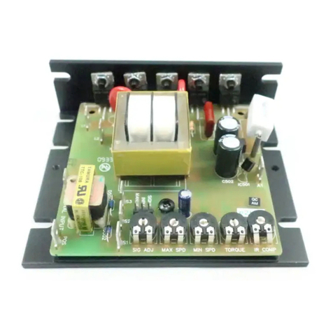
Minarik PCM21000A User manual

Minarik

Minarik PCM21000A User manual

Minarik MM21036A User manual

Minarik

Minarik MM21036A User manual
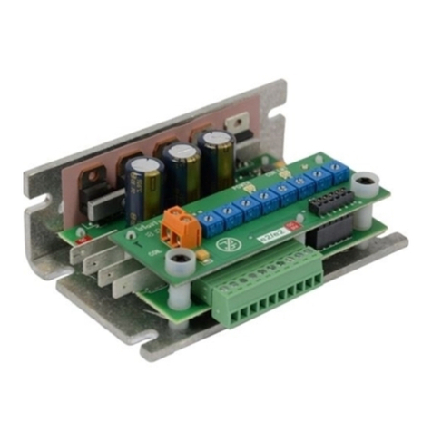
Minarik DC30-12-4Q-L User manual

Minarik

Minarik DC30-12-4Q-L User manual
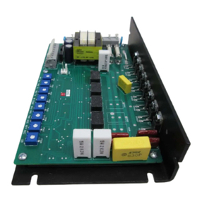
Minarik RG300 Series User manual

Minarik

Minarik RG300 Series User manual
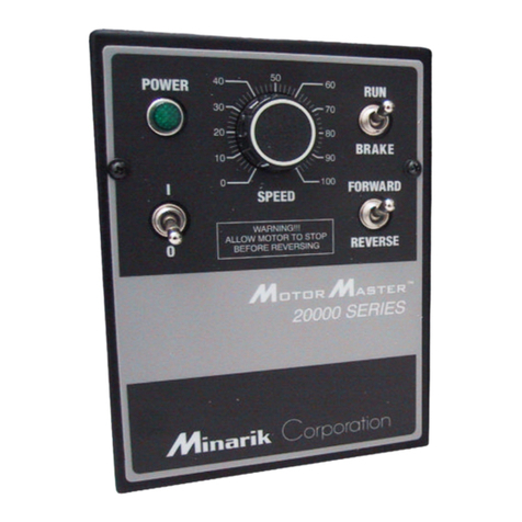
Minarik MM20000A Series User manual

Minarik

Minarik MM20000A Series User manual
Minarik MM-PCM Series User manual

Minarik

Minarik MM-PCM Series User manual
Minarik MMRG Series User manual

Minarik

Minarik MMRG Series User manual
Minarik M2-D User manual

Minarik

Minarik M2-D User manual

Minarik XP-AC-SL Series User manual

Minarik

Minarik XP-AC-SL Series User manual

Minarik MMBOSS Series User manual

Minarik

Minarik MMBOSS Series User manual
Minarik MMRG30U User manual

Minarik

Minarik MMRG30U User manual

Minarik PCM23000A Series User manual

Minarik

Minarik PCM23000A Series User manual

Minarik XL1100A User manual

Minarik

Minarik XL1100A User manual

Minarik Motor Master 20000 Series User manual

Minarik

Minarik Motor Master 20000 Series User manual

Minarik BOSS Series User manual

Minarik

Minarik BOSS Series User manual

Popular DC Drive manuals by other brands
Siemens SIDOOR AT12 manual

Siemens

Siemens SIDOOR AT12 manual

Homematic IP HmIP-VDMOT Installation and operating manual
Homematic IP

Homematic IP HmIP-VDMOT Installation and operating manual

Becker C01a Assembly and operating instructions
Becker

Becker C01a Assembly and operating instructions

INVT Goodrive300 Series Operation manual
INVT

INVT Goodrive300 Series Operation manual

SEW-Eurodrive MOVIMOT MM D Series Compact operating instructions
SEW-Eurodrive

SEW-Eurodrive MOVIMOT MM D Series Compact operating instructions

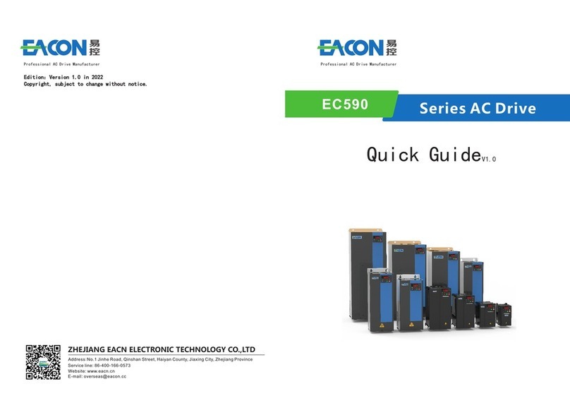
EACON EC590 Series quick guide

EACON

EACON EC590 Series quick guide

SOMFY Sunea Screen 40 io instructions

SOMFY

SOMFY Sunea Screen 40 io instructions

Siemens simovert masterdrives operating instructions

Siemens

Siemens simovert masterdrives operating instructions

Toshiba T300BMV2 instruction manual

Toshiba

Toshiba T300BMV2 instruction manual

GFA ELEKTROMAT ST 30.24-40,00 installation instructions

GFA

GFA ELEKTROMAT ST 30.24-40,00 installation instructions

Advantech Automation1 iXC4 Hardware manual

Advantech

Advantech Automation1 iXC4 Hardware manual

Unitek TVD6.2-RS manual

Unitek

Unitek TVD6.2-RS manual

Nidec Answer Drives 700E Installation & operating instructions
Nidec

Nidec Answer Drives 700E Installation & operating instructions

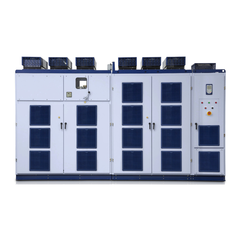
WEG MVW3000 Series user manual

WEG

WEG MVW3000 Series user manual

D+H VCD 204-K-TMS-B Original instructions

D+H

D+H VCD 204-K-TMS-B Original instructions

SOMFY FREEVIA 600 Technical data sheet
SOMFY

SOMFY FREEVIA 600 Technical data sheet

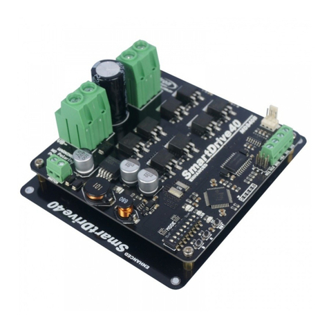
Cytron Technologies SmartDrive40 user manual
Cytron Technologies

Cytron Technologies SmartDrive40 user manual

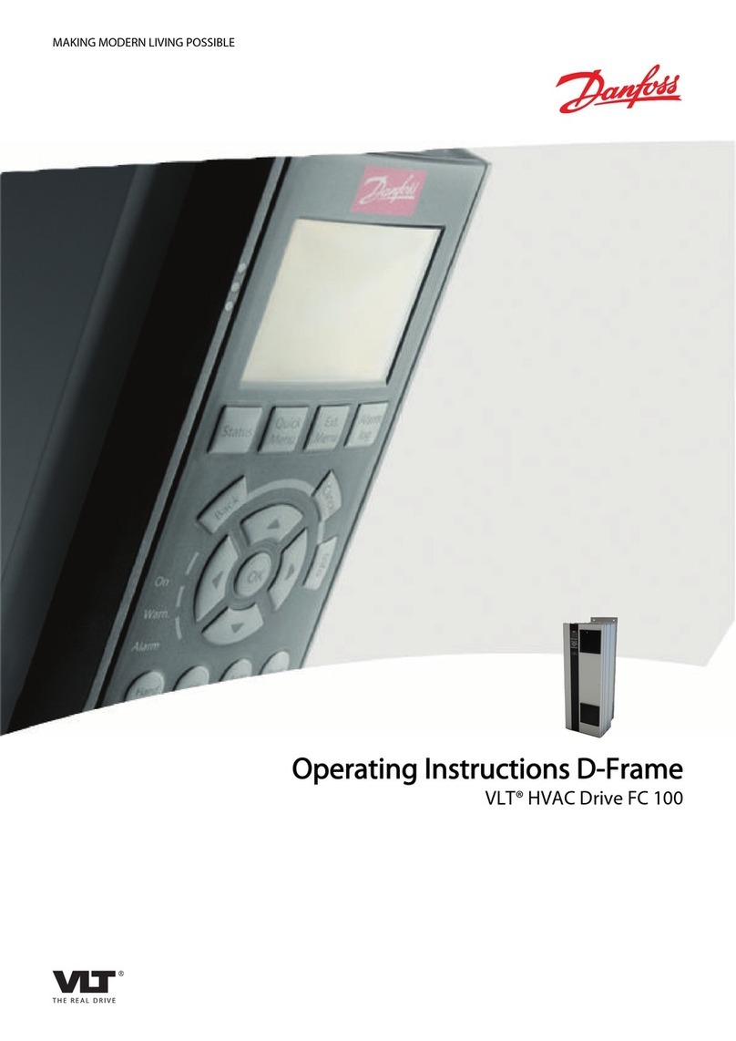
Danfoss VLT HVAC FC 100 operating instructions

Danfoss

Danfoss VLT HVAC FC 100 operating instructions

manuals.online logo
manuals.online logoBrands
  • About & Mission
  • Contact us
  • Privacy Policy
  • Terms and Conditions

Copyright 2025 Manuals.Online. All Rights Reserved.