manuals.online logo
Brands
  1. Home
  2. •
  3. Brands
  4. •
  5. Minarik
  6. •
  7. DC Drive
  8. •
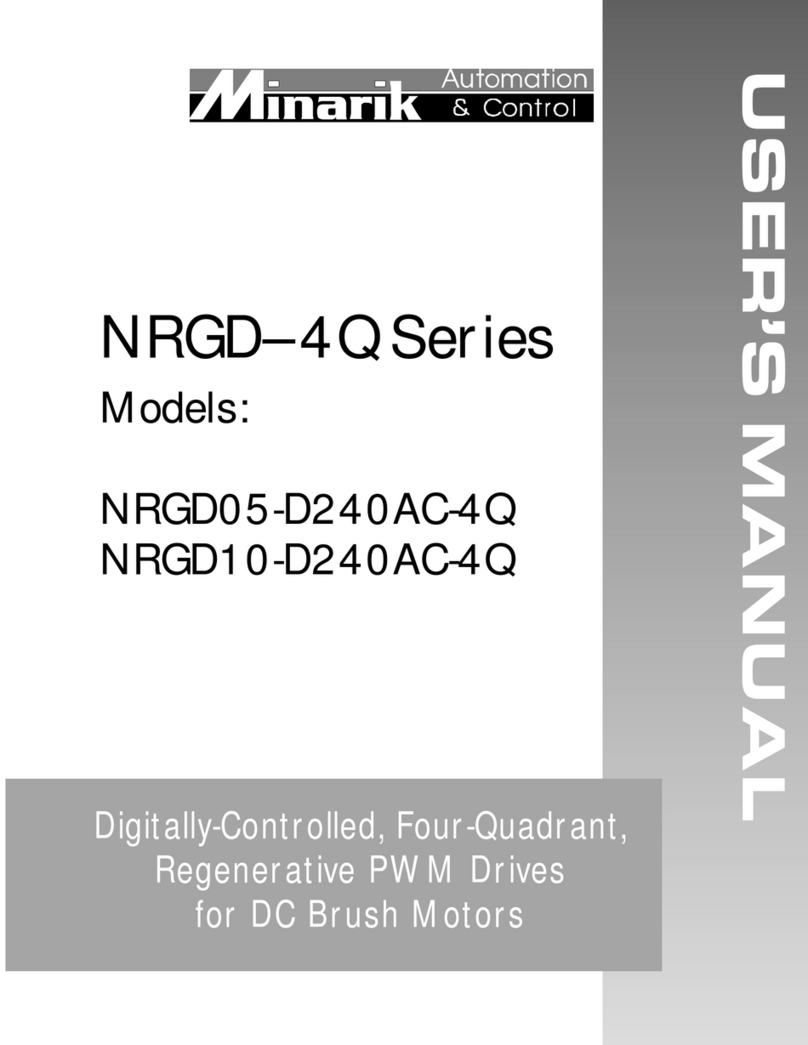
  9. Minarik M2-D User manual

Minarik M2-D User manual

S1S2 S1S2S3
MIN-SPEED-MAX
IR COMP
S3
L2
L1
A-/A
A+/A
1
ACC/DEC CUR LIM
A -- INHIBIT -- B
A B
J504 J505 J507 J506
A-B
IC503
IC502
J503
J502
C507
C508
180 90
C510
C506
C505
C503
D501 D502
U1
R503
R501
C15
Q504 Q503
Q502
R38
MOV502
C501
J501
Y501
C504
A- / B A+ / B
M
TORQUE
SPEED
INDEP.
RATIO
6 PLACES
.675 [17.2]
2.43 [61.7]
3.175 [80.7]3.175 [80.7]
.186 [5]
180 90
QUICK START GUIDE
M2-D
DIMENSIONS
SPECIFICATIONS
* Heatsink (part number 223-0159) is required if one side provides more than 5A or the total output of both
sides is more than 6.5A.
Dual Motor Control SCR DC Drive
CONNECTIONS
S1S2 S1S2S3
MIN-SPEED-MAX
IR COMP
S3
L2
L1
A-/A
A+/A
1
ACC/DEC CUR LIM
A -- INHIBIT -- B
A B
J504 J505
J507 J506
A-B
IC503
IC502
J503
J502
C507
C508
180 90
C510
C506
C505
C503
D501 D502
U1
R503
R501
C15
Q504 Q503
Q502
R38
MOV502
C501
J501
Y501
C504
A- / B A+ / B
M
TORQUE
SPEED
INDEP.
RATIO
180 90
LINE
VOLTAGE
INPUT
115 VAC
or
230 VAC
MASTER
POWER
SWITCH
FUSE
MOTOR A MOTOR B
SPEED A
POTENTIOMETER
RATIO OR SPEED B
POTENTIOMETER
CLOSE TO INHIBIT DRIVE
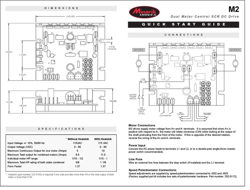
Motor Connections
M2-D drives supply motor voltage from A+ and A- terimnals. It is assumed that when A+ is
positive with respect to A-, the motor will rotate clockwise (CW) while looking at the output of
the shaft protruding from the front of the motor. If this is opposite of the desired rotation,
reverse the wiring of the A+ and A- terminals.
Power Input
Connect the AC power leads to terminals L1 and L2, or to a double-pole single-throw master
power switch (recommended). Suitable for use on a circuit capable of delivering not more than
5000 rms symetrical Amperes, 240 Volt maximum.
Line Fuse
If 115 VAC input line is used, wire an external line fuse in the hot leg between the stop switch
(if installed) and the L1 terminal. If 230 VAC input is used, fuse both legs.
Speed Potentiomenter Connections
Speed adjustments are supplied by speed potentiometers connected to J507 and J506
(Factory supplied pot kit includes two sets of potentiometer hardware. Part number: 202-0112).
Input Voltage +/- 10%, 50/60 Hz
Output Voltage (VDC)
Maximum Continuous Output from each side (Amps)
Maximum Total output from both sides (Amps)
HP Rating for each side
Maximum Total HP rating of both sides
Form Factor
115 VAC
0 - 90
5
6.5
1/15 - 1/2
5/8
230 VAC
0 - 180
5
6.5
1/8 - 1
1 1/4
* Without Heatsink
1.37
115 VAC
0 - 90
10
11.5
1/15 - 1
1 1/8
230 VAC
0 - 180
10
11.5
1/8 - 2
2 1/4
* With Heatsink
1.37
Copyright 2006 by Minarik Corporation - All rights reserved. No part of this document may be reproduced or transmitted in any form without
written permission from Minarik Corporation. The information and technical data in this document are subject to change without notice.
Minarik Corporation and its Divisions make no warranty of any kind with respect to this material, including, but not limited to, the implied
warranties of its merchantability and fitness for a given purpose. Minarik Corproation and its Divisions assume no responsibility for any
errors that may appear in this document and make no commitment to update or to keep current the information in this document.
mvd101403
CALIBRATION / OPERATION
MOTOR VOLTAGE SELECTION
Use J504 to match the motor voltage rating for motor A and J505 for motor B. ( Jumper on pins 1 & 2 for 180
VDC, 2 & 3 for 90 VDC.
INDEPENDENT MODE (Jumper on pins 1 & 2 of J503)
There are two sets of potentiometers independently used to adjust each motor operation. Each set consists of
five on board trimmer potentiometers and one external potentiometer (commonly called SPEED POT). To
calibrate one side (A or B), use the following procedure for speed mode:
1. Turn the SPEED POTENTIOMETER A (B) to full CCW. Use MIN SPEED A (B) trimmer potentiometer
to adjust minimum speed for motor A (B).
2. Turn the SPEED POTENTIOMETER A (B) to full CW. Use MAX SPEED A (B) trimmer potentiometer to
adjust maximum speed for motor A (B). Repeat steps 1 and 2 a few times due to a level of interaction
between MIN SPEED and MAX SPEED pots.
3. Set the CUR LIM A (B) to full CCW. Turn the SPEED POTENTIOMETER A (B) to full CW. Stall the
motor shaft and turn the CUR LIM A (B) CW until the desired current limit is reached.
4. Set the IR COMP A (B) to full CCW. Set the motor speed at approximately half of the rated speed. Load
motor to its full load. Keep turning the IR COMP CW until the speed equals the no load speed.
5. Use ACC/DEC A (B) trimmer potentiometer to adjust acceleration (deceleration) ramp time.
RATIO MODE (Jumper on pins 2 & 3 of J503)
In RATIO MODE, SPEED POT A is used to adjust the speed of both motors, while SPEED POT B sets the ratio
between speeds. Turning the SPEED POT B CW will increase speed of motor B thus increasing the ratio
speed B/speed A. MIN SPEED B and MAX SPEED B are now used to adjust minimum and maximum ratio.
INHIBIT
Short inhibit terminals A(B) to bring motor A(B) to a stop. Inhibit A(B) is independant of inhibit B(A). The inhibit A
and inhibit B can be paralleled together.
J501
J501 is used by the factory to program the M2-D drive. Do NOT add any jumpers to J501.
TORQUE MODE (Jumper on pins 1 & 2 of J502 and pins 1 & 2 on J503)
TORQUE MODE regulates motor current (torque). In TORQUE MODE, the external potentiometer A (B) sets the
torque reference for Motor A (B) and the CUR LIM trimmer potentiometer A (B) sets the speed limit for Motor A
(B). The MIN SPEED A (B) and MAX SPEED A (B) are used to adjust the minimum and maximum torque
available.
Rotation: CW = Clockwise CCW = Counterclockwise
S1S2 S1S2S3
MIN-SPEED-MAX
IR COMP
S3
ACC/DEC CUR LIM
A B
J507 J506
A-B
C507
C508
SPEED A
POTENTIOMETER
CW
RATIO SPEED B
POTENTIOMETER
CW
TRIMMER POTS
FOR MOTOR B
TRIMMER POTS
FOR MOTOR A
U1
R503
C15
C501
A- / B
J502
J503
TORQUE
SPEED
INDEP.
RATIO
1
2
3
PINS
J505
180
90
J504
180
90
M2-D POTENTIOMETER CONNECTIONS

Other Minarik DC Drive manuals

Minarik XL1100A User manual

Minarik

Minarik XL1100A User manual

Minarik NRGD-4Q Series User manual

Minarik

Minarik NRGD-4Q Series User manual

Minarik MMRG Series User manual

Minarik

Minarik MMRG Series User manual

Minarik HTL05-D-4Q User manual

Minarik

Minarik HTL05-D-4Q User manual
Minarik MM21036A User manual

Minarik

Minarik MM21036A User manual

Minarik BOSS Series User manual

Minarik

Minarik BOSS Series User manual

Minarik M2 User manual

Minarik

Minarik M2 User manual

Minarik MM300 Series User manual

Minarik

Minarik MM300 Series User manual

Minarik Motor Master 20000 Series User manual

Minarik

Minarik Motor Master 20000 Series User manual

Minarik XP-AC-SL Series User manual

Minarik

Minarik XP-AC-SL Series User manual

Minarik VFD Series User manual

Minarik

Minarik VFD Series User manual

Minarik MMRG30U User manual

Minarik

Minarik MMRG30U User manual

Minarik RG500 Series User manual

Minarik

Minarik RG500 Series User manual

Minarik XP-AC Series User manual

Minarik

Minarik XP-AC Series User manual

Minarik VFDP4X04-D230-PCM User manual

Minarik

Minarik VFDP4X04-D230-PCM User manual

Minarik RG501A User manual

Minarik

Minarik RG501A User manual
Minarik NRG-2Q Series User manual

Minarik

Minarik NRG-2Q Series User manual

Minarik BOSS Series User manual

Minarik

Minarik BOSS Series User manual

Minarik MM20000 Series User manual

Minarik

Minarik MM20000 Series User manual

Minarik MM20000A Series User manual

Minarik

Minarik MM20000A Series User manual

Minarik RG300 Series User manual

Minarik

Minarik RG300 Series User manual

Minarik MMBOSS Series User manual

Minarik

Minarik MMBOSS Series User manual
Minarik LV Series User manual

Minarik

Minarik LV Series User manual

Minarik RG5500U User manual

Minarik

Minarik RG5500U User manual

Popular DC Drive manuals by other brands

Applied Motion Products PDO 2035 user manual

Applied Motion Products

Applied Motion Products PDO 2035 user manual

JVC PK-VS4GD2G instructions

JVC

JVC PK-VS4GD2G instructions

Mitsubishi Electric Melservo-Jet MR-JET-G user manual

Mitsubishi Electric

Mitsubishi Electric Melservo-Jet MR-JET-G user manual

Rockwell Automation Allen-Bradley PowerFlex 400P Series quick start

Rockwell Automation

Rockwell Automation Allen-Bradley PowerFlex 400P Series quick start

Fujitsu MAN3735 SERIES installation guide

Fujitsu

Fujitsu MAN3735 SERIES installation guide

Danfoss Holip HLP-V Series instructions

Danfoss

Danfoss Holip HLP-V Series instructions

SEW-Eurodrive Movidrive MDX61B operating instructions

SEW-Eurodrive

SEW-Eurodrive Movidrive MDX61B operating instructions

Pentair IntelliFlo installation guide

Pentair

Pentair IntelliFlo installation guide

SOMFY S&SO-RS100 io instructions

SOMFY

SOMFY S&SO-RS100 io instructions

Veichi AC300 Series Technical manual

Veichi

Veichi AC300 Series Technical manual

Delta Electronics Elevator Drive VFD-VL user manual

Delta Electronics

Delta Electronics Elevator Drive VFD-VL user manual

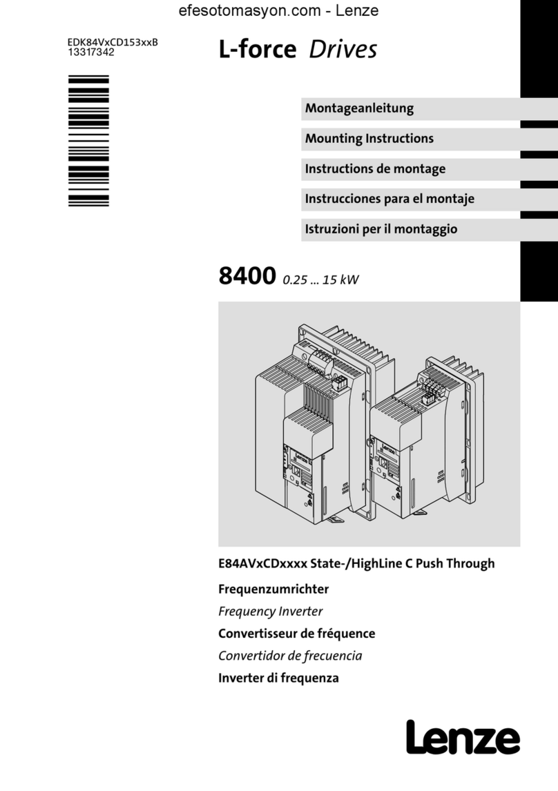
Lenze L-force E84AVSCE StateLine C Series Mounting instructions

Lenze

Lenze L-force E84AVSCE StateLine C Series Mounting instructions

Siemens MICROMASTER operating instructions

Siemens

Siemens MICROMASTER operating instructions

G-U ELTRAL OA Installation and operating instructions

G-U

G-U ELTRAL OA Installation and operating instructions

Lenze EZAEVA Series Mounting instructions

Lenze

Lenze EZAEVA Series Mounting instructions

Binks 31-396 manual

Binks

Binks 31-396 manual

Carel Power + PSD1 Series Technical leaflet

Carel

Carel Power + PSD1 Series Technical leaflet

ThyssenKrupp Mini gearless DAF270 operating manual

ThyssenKrupp

ThyssenKrupp Mini gearless DAF270 operating manual

manuals.online logo
manuals.online logoBrands
  • About & Mission
  • Contact us
  • Privacy Policy
  • Terms and Conditions

Copyright 2025 Manuals.Online. All Rights Reserved.