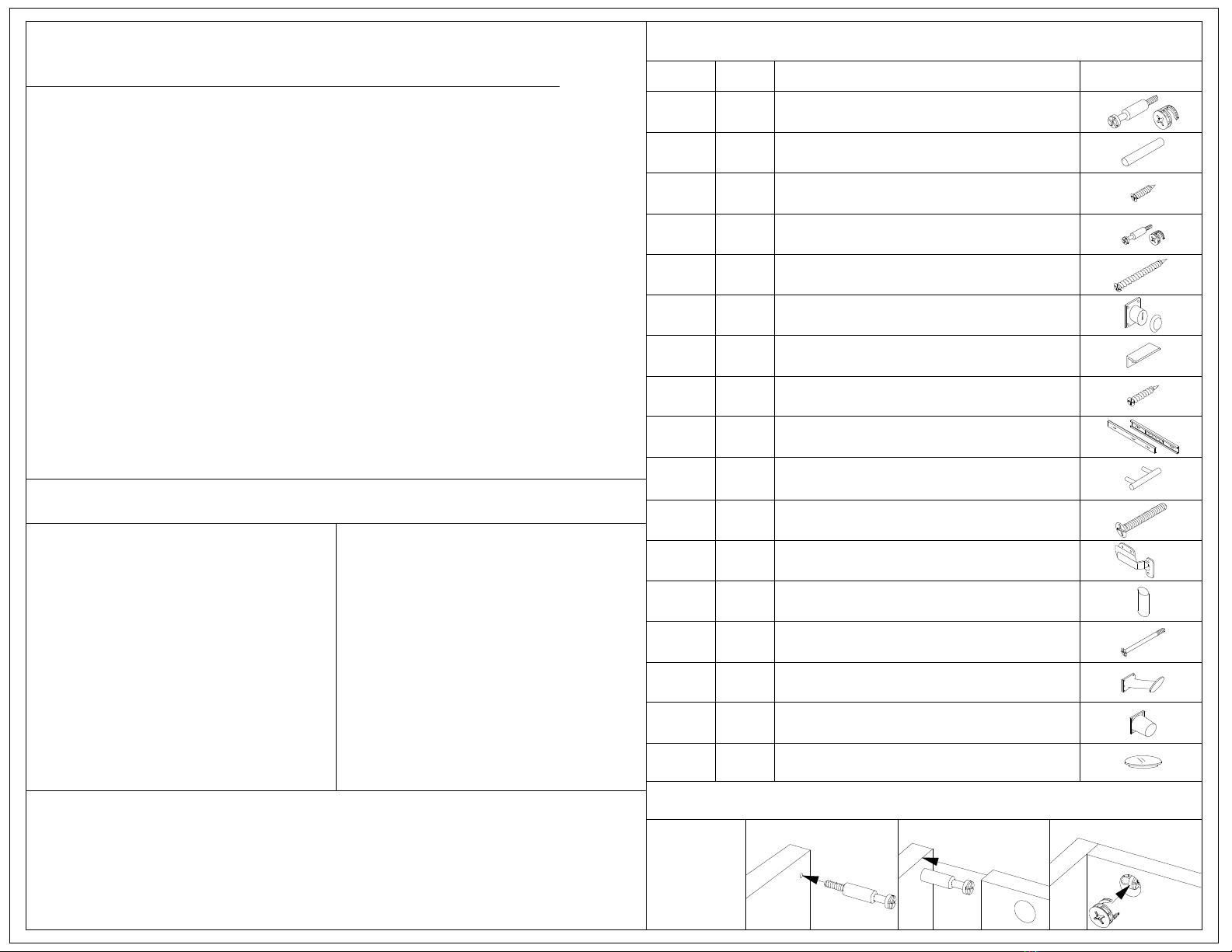
Minerva Tavola 2015 User manual

Pre-Assembly
- Please read all instructions carefully before assembling
this desk.
- For your safety, assembly by two or more adults is
strongly recommended.
- Keep these instructions for future use.
- Use only vendor supplied hardware to assemble this
item. Using unauthorized hardware could jeopardize
the structural integrity of the item.
Tavola
Reception Desk
Model # 2015
Important Safety Instructions
Assembly Instructions
- Remove all parts and hardware from the box. Place
them on a carpeted or scratch-free work surface, as
this will avoid damaging parts during assembly. The
shipping box provides an ideal work surface.
- To avoid accidently discarding small parts or hardware,
do not dispose any packaging or contents of the
shipping carton until assembly is complete.
- Use the parts and hardware list on the right to identify
and seperate all of the pieces included.
- The illustrations provided allow for easier assembly
when used in conjunction with the assembly
instructions.
- The use of powertools to aid in assembly is not
recommended. Power tools can damage hardware and
split wood.

Care Instructions
Part Qty. Description Sketch
40A Large cam lock set
26B
Small cam lock set4D
Small wood screw
50
C
ELarge wood screw
4
Wood dowel**
PARTS LIST*
*Check inside all boxes, cabinets, and drawers for boxes
and bags of parts before beginning assembly.
**Dowels may already be inserted in the various wood panels.
9 - Drawer support
10 - Drawer bottom
11 - Drawer left side
12 - Drawer right side
13 - Drawer rear panel
14 - Drawer front panel
15 - Cabinet door
16 - Glass top
1 - Back panel
2 - Left side panel
3 - Right side panel
4 - Top panel
5 - Desk top panel
6 - Inner shelf
7 - Desk bottom panel
8 - Interior divider
Components (Label - Description)
- Dust often using a clean, soft, dry and lint-free cloth.
- Blot spills immediantly and wipe with a clean, damp
cloth.
- We do not recommend the use of chemical cleansers,
abrasives, or furniture polish on our lacquered finish.
- Hardware may loosen overtime. Periodically check to
make sure all connections are tight. Re-tighten if
necessary.
L 2
Slide second panel over
cam lock screw.
Slide cam lock over head of
screw, then turn to
tighten.
Screw the cam lock screw
into the first panel.
F 1 Drawer lock
G Drawer lock catch
1
4H Medium wood screw
I 2 Drawer glide set
2Drawer handleJ
K 4 Handle screw
Hinge
M 6 Steel support tube
N 6 Glass top screw
Foot4O
Support leg (5' model ONLY)
2P
Cam lock cover40
Q
Using a
cam lock
Phillips-head screwdriver required (not included)

1) Remove the hinges (L) from the cabinet door (15). The door will be reattached after final assembly.
2) Align the top holes of the hinges (L) with the marks on the right side panel (3) from step 1.2.
3) Maintaining alignments with the marks, screw the hinges into the right side panel (3) using 8 screws (C).
3
8
x2
x4
C
C
C
C
C
Marks
II
5/8"
2 - Mounting outer drawer glides
Marks
x4
1) Fit the "bowl" of the hinges inside the notches cut into the door,
then affix to the cabinet door (15) with 2 small screws (C) each.
2) Secure the door handle to the cabinet door (15) with 2 handle screws (K).
3) Fold the hinges all the way in, to 90-degree angle, as if the door were closed.
C
3
J
K
K
L
L
C
C
C
3
3
L
L
L
L
L
1.3 - Mounting hinges (3 of 3)
Marks
1.1 - Mounting hinges (1 of 3)
J
K x2
15
15
C
C
L
x1
x8
1) Hold the door (15) perpendicular to the right side panel such that the door front (15) is flush
with the front edge of the right side panel (3).
2) Bottom edge of door should be approx. 1/16" above bottom edge of side panel (see magnification).
3) Using a pencil or a screw, create a mark in the two upper holes of both hinges on the right side panel (3).
3
~1/16"
15
1.2 - Mounting hinges (2 of 3)
I x2
1) Place outer drawer glides over small pilot hole guides.
Set drawer glides (I) in 5/8" from the front edges of
the interior divider (8) and the right side panel (3).
2) Secure each drawer glide with 2 screws (C).
*Note: The drawer glides with the rolling silver plate are the outer glides.

1/2"
7.75" from edge
(9.75" on the
5 foot Tavola
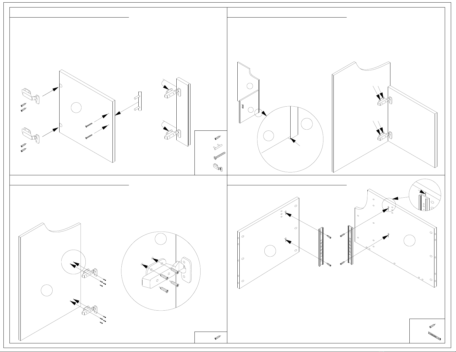
1) Locate both drawer sides (11 and 12) and the inner drawer glides (I).
2) On the outside of the drawer sides (11 and 12), align the end of the inner drawer guide
flush with the front edge of the sides (see magnifications).
The bottom curved lip of the metal guide should 1/2" up from bottom of the drawer side.
3) Secure each drawer glide with 2 screws (C).
3/4" from top
This is 7-3/4" for the 4 foot desk,
and 9-3/4" for the 5 foot desk
Flush to the edge.
1/2"
1) Looking at the top panel (4) as shown, center the drawer lock
catch (G) horizontally between the holes and right edge
as shown (approximately 7-3/4" from edge).
12
11
C
x2
C x4
I
I
I
C
C
C
C
Glide
Notch
x1G
x2
9
8
6
B
A
A
A
B
A
A x5
x4
B
B
A
B
A
x3
x5
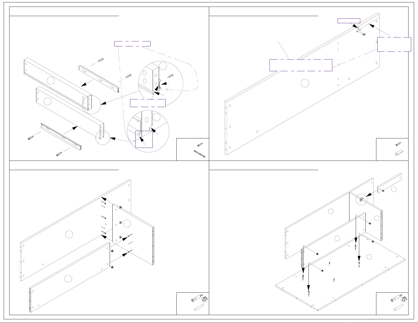
1) Screw 3 cam lock screws (A) and insert 2 dowels (B)*
into the top of the interior divider (8) as shown.
2) Use 3 cam locks to secure interior
divider (8) to top panel (5).
3) Screw 2 cam lock screws (A) and insert 1 dowel (B)
into the side of the interior divider (8) as shown.
4) Secure inner shelf (6) to interior
divider (8) using 2 cam locks (A).
B
A
A
B
A
A
B
B
A
6
5
8
*Note: Dowels may already be inserted.
Glide
11
12
4
G
2) Align the front edge of the catch 5/8"
from front edge of top panel (4).
3) Secure with 2 screws (C).
1
5
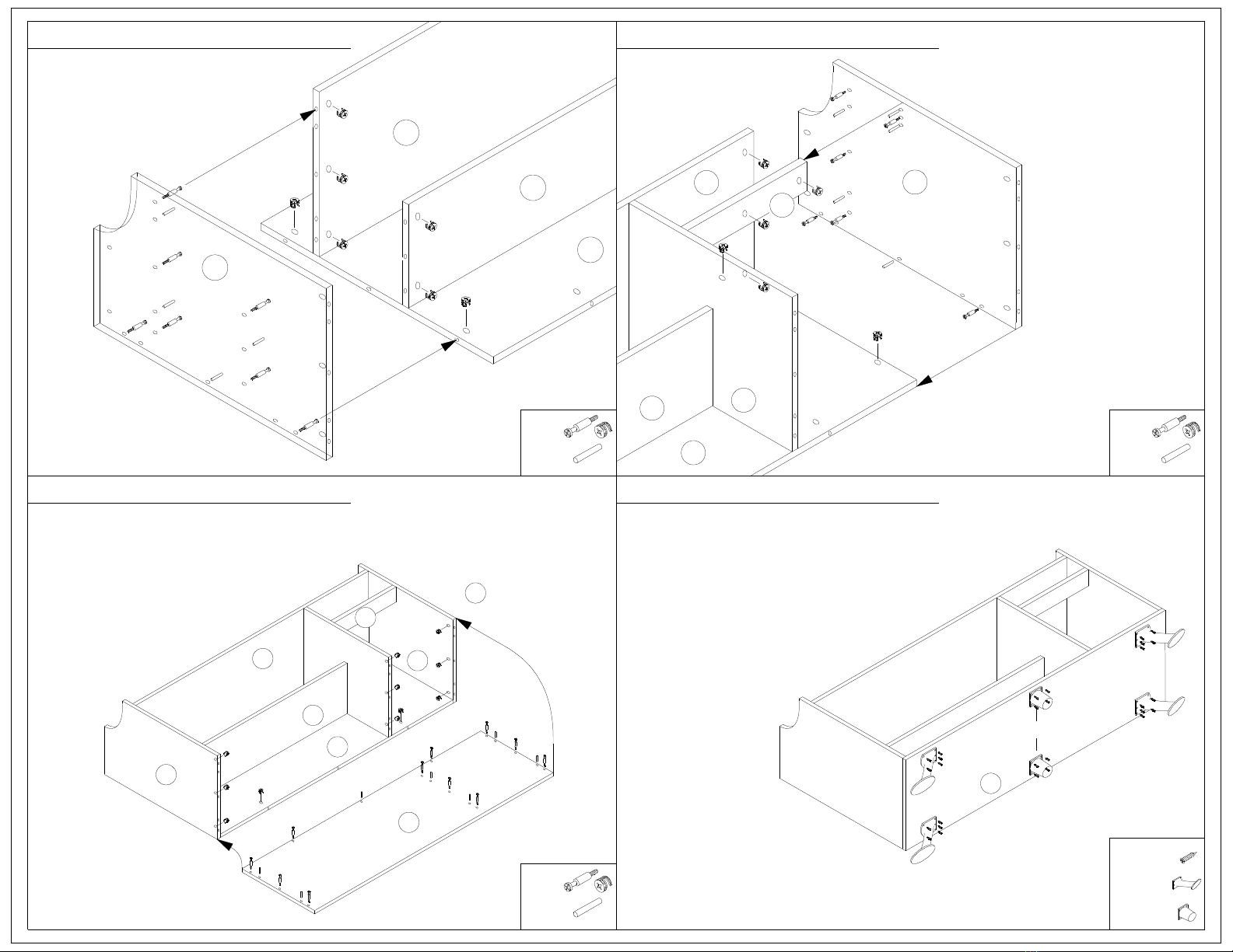
1) Screw 4 cam lock screws (A) into the bottom
panel (1) as shown.
2) Insert 2 dowels (B) into the bottom panel (1).
3) Secure assembly to the back panel (1)
with 4 cam locks (A).
4) Locate the three holes on the
outside of the interior
divider (8) (see diagram).
5) Insert 2 dowels (B) in the outer
holes and screw 1 cam lock
screw (A) into the center hole.
6) Secure drawer support (9) to
interior divider (8) with 1 cam
lock (A).
CC
Notch
3 - Mounting inner drawer glides 4 - Mounting drawer lock catch
6 - Assembly and mounting of inner desk
5 - Assembly of inner desk

9 - Attaching the bottom panel
7 - Attaching left side panel
10 - Attaching feet
8 - Attaching right side panel
5
1
1) Screw feet (O) onto bottom panel (7) using 5 screws each (C)**
**Note: 5' models include 2 additional support feet (P) to be centered
between the feet (O) and secured with 4 screws (C) each.
There are NO pilot holes for the feet.
Measure distance from edges to ensure
symmetric placement and keep feet
bottom inside the footprint of the
bottom panel (7) so they do not
protrude past the glass top.
2) Stand unit upright.
ALWAYS use 2 or more people
for this step.
Place all feet on the ground at the same time!
Failure to do so could cause the bottom
panel or feet to break.
1) Screw 7 cam lock screws (A) into
right side panel (2) as shown.
2) Insert 4 dowels (B) into right
side panel (2).
A
B
A
B
2
A
B
A
A
B
A
A
6
3) Secure right side panel (2) to the
assembly with 7 cam locks (A).
1) Screw 11 cam lock screws (A) into bottom panel (7) as shown.
2) Insert 7 dowels (B) into bottom panel (7) as shown.
3) Align bottom panel (7) with the assembly
and secure with 11 cam locks (A).
B
x7
x4
A x11
B x7
A
B
BA
A
A
A
BA
B
A
A
BA
B
A
A
B
1
A
5
3
2
6
8
9
7
C (5x)
O
C (5x)
7
O
O
O
P
P
C (4x)
C (4x)
C (5x)
C (5x)
C
O
P
x20
(+8)
(x2)
x4
Only for 5' model
1) Screw 6 cam lock screws (A)
into right side panel (3) as shown.
2) Insert 4 dowels (B) into right side
panel (3) as shown.
x5
x6
B
3) Align drawer support (9) with
the 2 dowels (B) and 1 cam
lock screw (A) on right side
panel (3),
4) Secure right side panel (3)
to the assembly with 6 cam
locks.
A
A
B
A
A
B
B
A
B
B
A
A
1
6
9
5
8
3

11
E
E
4
16
M
x6
x4
(+2)
Center supports only on 5' model.
x4
(+2)
N
4) Attach glass to top by sliding the 4 glass top
screws (N) up through the top panel (4) and
support tubes (M) and screwing them into the
steel inserts in the glass top (16).
*Note: The 5' model will have 2 additional support
tubes (M) in the center, as shown.
M
M
M
M
M
M
N
N
N
N
N
N
A
A
A
A
A
A
14
12
10
13
x1
x4
x4D
K x2
1) Screw lock (F) into drawer face (14) using the 4 included
screws (H), then place the cap on from the front.
2) Screw the handle (J) on to drawer face (14) using 2 handle screws (K).
3) Screw 4 small cam lock screws (D) into back of drawer face (14).
4) Insert drawer bottom (10) into grooves on drawer sides (11 and 12),
then secure to drawer face (14) with 4 cam locks (D).
5) Fit drawer back (13) over drawer bottom (10) and secure to
sides (11 and 12) using 4 large wood screws (E).
E
F
x4H
J x1
H (x4)
D
E
E
F
K
K
J
D
D
D
x40Q
A
x3
x6
B
A
1) Screw 6 cam lock screws (A) into the outer holes on each edge
of the underside of the top panel (4).
These will be secured with cam locks (A) in step 13.
2) Align the 4* steel support tubes (M) with the holes
in the top of the top panel (4).
3) Align glass top (16) with the steel tubes (M). 4
1) Slide drawer onto glides.
2) Re-attach door to hinges with
2 screws (C) per hinge.
3) Cover all 40 cam locks with
included plastic covers (Q).
1) Insert 3 dowels (B) into the center hole in the top
of each side on the desk assembly.
2) Set glass and top panel assembly onto desk
assembly and secure with 6 cam locks (A).
16
BA
AA
A
A
A
B
B
11 - Assembling the desk top
13 - Assembling the drawer
12 - Attaching the top
14 - Final assembly
Table of contents
Other Minerva Indoor Furnishing manuals
Popular Indoor Furnishing manuals by other brands

Forever Redwood
Forever Redwood ROUND SOLID WOOD SIDE TABLE Assembly instructions

Monarch Specialties
Monarch Specialties I 7102 Assembly instructions

Amart Furniture
Amart Furniture KIRBY 74940 Assembly instruction

Dowell
Dowell 032 Series installation guide

RTA
RTA Office 11 Combo Assembly instructions

Amart Furniture
Amart Furniture CABOS 72790 Assembly instruction