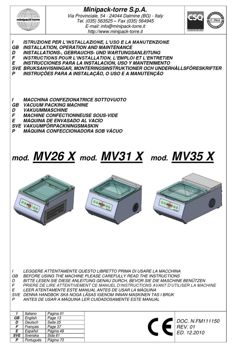
Minipack-Torre MV31 Installation and operating instructions

ISTRUZIONE PER L’INSTALLAZIONE, L’USO E LA MANUTENZIONE
INSTALLATION, OPERATION AND MAINTENANCE
INSTALLATIONS, GEBRAUCHS UND WARTUNGSANWEISUNGEN
INSTRUCTIONS POUR L’INSTALLATION, L’EMPLOI ET L’ENTRETIEN
INSTRUCCIONES PARA LA INSTALACION, USO Y MANTENIMENTO
BRUKSANVISNINGAR, MONTERINGSINSTRUKTIONER OCH UNDERHÅLLSFÖRESKRIFTER
CONFEZIONATRICE SOTTOVUOTO
VACUUM PACKING MACHINE
VAKUUMMASCHINE
MACHINE CONFECTIONNEUSE SOUS-VIDE
MAQUINA CONFECCIONADORA
VAKUUMFÖRPACKNINGSMASKIN
Mod. MV31
Mod. MV35
IITALIANO Pagina 1
GB ENGLISH Page 7
DDEUTSCH Seite 13
FFRANÇAIS Page 19
EESPAÑOL Página 25
SVE SVENSKA Sid. 31
DOC. N. FM111022
REV. 03
Ed: 12.2003

1
INDICE
Capitolo 1. Introduzione
1.1. Prefazione…………………………………......................…………………………. 2
1.2. Prestazioni della macchina confezionatrice.....................……………………….. 2
1.3. Identificazione della macchina.......................................………………………… 2
1.4. Peso e dimensioni della macchina imballata...................……………………….. 2
1.5. Peso e dimensioni della macchina..................................……………………….. 2
Capitolo 2. Installazione della macchina
2.1. Trasporto e posizionamento............................................……………………….. 2
2.2. Condizioni ambientali.....................................................………………………… 2
2.3. Schema d’installazione.....................................................………………………. 2
2.4. Utenze.....................................................…………………………………………. 3
2.4.1. Collegamento elettrico.....................................................………………. 3
2.4.2. Collegamento gas…………………………………………………………… 3
Capitolo 3. Regolazione ed approntamento macchina
3.1. Regolazione....................................................................………………………... 3
Capitolo 4. Limitazioni e condizioni d’uso della macchina
4.1. Ciò che non si deve confezionare...................................……………………….. 4
Capitolo 5. Caratteristiche delle buste
5.1. Buste da adoperare.........................................................……………………….. 4
Capitolo 6. Norme di sicurezza
6.1 Avvertimenti.....................................................................……………………….. 5
Capitolo 7. Manutenzione ordinaria
7.1. Cautele per interventi di manutenzione ordinaria.........….……………………… 5
7.2. Pulizia barra saldante................................…....................……………………… 5
7.3. Cambio del teflon e della lama saldante………….............……………………… 5
7.4. Cambio della guarnizione del coperchio…………………………………………... 5
7.5. Pulizia della macchina....................................................………………………… 5
7.6. Cambio dell’olio e del filtro della pompa............................................………….. 5
7.7. Schema elettrico………....................................................………………………. 6
7.8. Schema pneumatico..........................................................……………………… 6
7.9. Smontaggio, demolizione e smaltimento residui…………………………………. 6
Capitolo 8. Garanzia
8.1. Cerificato di garanzia………………………………………………………………… 6
8.2. Condizioni di garanzia……………………………………………………………….. 6
Dichiarazione CE di conformità…………………………………………………….. 37

2
Capitolo 1. Introduzione
1.1. Prefazione
Il presente manuale è redatto nel rispetto della norma UNI 10893 del Luglio 2000.
È rivolto a tutti gli utilizzatori al fine di consentire un corretto uso della macchina. Conservarlo in luogo facilmente accessibile
vicino alla macchina e noto a tutti gli utilizzatori.
Il presente manuale è parte integrante della macchina ai fini della sicurezza.
Per migliorare la comprensione precisiamo di seguito i simboli utilizzati.
ATTENZIONE:
Norme antinfortunistiche per l’operatore. Tale avvertimento indica la presenza di pericoli che
possono causare lesioni a chi sta operando sulla macchina.
AVVERTENZA:
Indica la possibilità di arrecare danno alla macchina e/o ai suoi componenti.
1.2. Prestazioni della macchina confezionatrice
Questa macchina rappresenta quanto di meglio la moderna tecnologia del sottovuoto possa esprimere. Per la sua
flessibilità, facile programmazione ed economicità rappresenta una soluzione validissima a chiunque deva confezionare
sottovuoto o in atmosfera modificata prodotti alimentari, eliminando il contatto di questi con l’ossigeno e contaminanti chimici
e biologici presenti nell’ambiente.
Questi risultati si ottengono grazie ad una programmazione della macchina che ci permette di ottenere il vuoto desiderato,
ottenendo un’estrazione pressoché totale dell’aria dall’interno della confezione.
In questo modo il vostro prodotto conserverà a lungo le sue caratteristiche organolettiche, di colore, sapore, aroma e
nutrizionali.
1.3. Identificazione della macchina
Per qualsiasi comunicazione con il costruttore, citare sempre il modello della macchina e il numero di matricola indicati sulla
targhetta applicata nella parte posteriore della macchina.
1.4. Peso e dimensioni della macchina imballata
MV31 Larghezza W = 470 mm Lunghezza l = 550 mm Altezza H = 550 mm Peso = 38 Kg
MV35 Larghezza W = 460 mm Lunghezza l = 710 mm Altezza H = 485 mm Peso = 54 Kg
1.5. Peso e dimensioni della macchina
MV31 Larghezza W = 390 mm Lunghezza l = 480 mm Altezza H = 325 mm Peso = 33 Kg
MV35 Larghezza W = 400 mm Lunghezza l = 605 mm Altezza H = 325 mm Peso = 46 Kg
Capitolo 2. Installazione della macchina
2.1. Trasporto e posizionamento
Nel trasporto e nel posizionamento della macchina si raccomanda di manovrare con molta cautela!
Se si trasporta a mano è necessario l’intervento di 2 persone.
Non capovolgere o inclinare la macchina! Questo da luogo alla fuoriuscita dell’olio dalla pompa che potrebbe
danneggiare la macchina stessa.
•Tagliare con la forbice la reggia (1) avendo cura di proteggersi gli occhi con degli occhiali.
•Togliere l’imballo superiore di cartone (2).
•Tagliare la reggia (3) che fissa la macchina al pallet.
•Sollevare la macchina e posizionarla sul piano di lavoro accertandosi che sia in un ambiente adatto, privo di materiali
infiammabili, gas, esplosivi.
2.2. Condizioni ambientali
Condizioni consentite negli ambienti in cui é collocata la macchina:
•Temperatura da + 5°C a + 40°C
•Umidità relativa da 30% a 90% senza condensazione
L’illuminazione del locale di utilizzo deve essere conforme alle leggi vigenti nel paese in cui è installata la macchina e deve
comunque essere uniforme e garantire una buona visibilità, per salvaguardare la sicurezza e la salute dell’operatore.
GRADO DI PROTEZIONE DELLA MACCHINA = IP20
IL RUMORE AEREO PRODOTTO DALLA MACCHINA È INFERIORE A 70 dB
2.3. Schema d’installazione
I Collegamento elettrico
H Collegamento gas

3
Capitolo 2. Installazione della macchina
2.4. Utenze
2.4.1. Collegamento elettrico
RISPETTARE LE NORME PER LA SICUREZZA SUL LAVORO!
Se la macchina non è dotata della spina di alimentazione utilizzare una spina adeguata ai valori di tensione e
amperaggio descritti nella targhetta dati e comunque conforme alle normative vigenti nel paese d’installazione.
È OBBLIGATORIA LA MESSA A TERRA!
Prima di effettuare il collegamento elettrico (13) assicuratevi che la tensione di rete corrisponda al voltaggio indicato
sulla targhetta in pos. (14), applicata nella parte posteriore della macchina e che il contatto di terra sia conforme alle
norme di sicurezza vigenti. In caso di dubbi sulla tensione di rete, contattate l’ente locale distributore dell’energia
elettrica.
2.4.2. Collegamento gas
Collegare l’impianto del gas (15), qualora la macchina ne sia predisposta, per mezzo del tubo (T), alla bombola del gas.
Regolare la pressione dell’impianto intorno alle 2atm, tenendo conto che la pressione max. di esercizio è di 4atm.
Se la pressione non è corretta, agire sulla manopola del riduttore di pressione (R).
Utilizzare gas specifico per il confezionamento alimentare, conforme alle normative vigenti in tema di additivi
alimentari, nel paese di utilizzo della macchina.
Non utilizzare miscele gassose con presenza di ossigeno, in percentuale superiore a quella
atmosferica (~ 19%).
Capitolo 3. Regolazione ed approntamento macchina
3.1. Regolazione
1. Interruttore generale
2. Pannello comandi
3. Pulsante di Start
4. Pulsante di selezione
5. Display
6. Pulsante di regolazione
7. Pulsante di regolazione
8. Pulsante di Stop
9. Led funzione vuoto ed extra vuoto
10. Led funzione gas
11. Led funzione saldatura
12. Led funzione rientro aria
CARATTERISTICHE SCHEDA ELETTRONICA
La macchina ha 9 programmi selezionabili.
I programmi P1÷P8 sono composti da 4 variabili modificabili.
Il programma P9 “Vuoto Esterno” è composto da solo 2 variabili modificabili (Vuoto ed Extravuoto).
Variabile Campo Caratteristiche Campo
1. Vuoto
2. Extravuoto
3. Gas
4. Saldatura
0 ÷ 99,9
0 ÷ 30
0 ÷ 99
0 ÷ 4
Valori espressi in %
Valori espressi in secondi
Valori espressi in % (non superare il 50%)
Valori espressi in secondi
Tutte le macchine confezionatrici vengono collaudate in fabbrica ed i parametri da noi impostati risultano essere
generalmente idonei per l’utilizzo della macchina
FASE 1 = ACCENSIONE
Premere l’interruttore generale (1) nella pos. ON. All’accensione della scheda appare sul display l’indicazione della versione
del software e successivamente dell’utimo programma eseguito (P1÷P9).
FASE 2 = SELEZIONE PROGRAMMI
Per selezionare il n° di programma premere i pulsanti (6) e (7).
FASE 3 = PROGRAMMAZIONE VARIABILI
Premendo il pulsante (4) si accede alla programmazione del programma visualizzato in quell’istante.
Premendo ancora il pulsante (4) appaiono in successione tutti i parametri del programma selezionato.
Premendo i pulsanti (6) e (7) si può incrementare o decrementare il valore del parametro visualizzato. La memorizzazione
dei parametri avviene quando, scorrendo un programma, si torna alla visualizzazione del numero di programma.
1) VUOTO
È possibile impostare un valore del parametro VUOTO da 0 a 99,9 %.
La percentuale di vuoto consigliata è del 99,9 %.
Lo stato di programmazione del parametro vuoto è segnalato mediante il led (9).
2) EXTRAVUOTO
Se si supera il valore 99.9 % si entra nella programmazione del parametro EXTRAVUOTO segnalato sull’ultimo digit del
display con la lettera E ed ha un valore compreso da 0 a 30 secondi. È il tempo in cui la pompa continua ad estrarre aria
dall’interno della campana dopo che la macchina ha raggiunto il livello di vuoto impostato. Questa funzione è utile per i
prodotti porosi nei quali l’evacuazione dell’aria è particolarmente difficile (es.: carne).

4
Capitolo 3. Regolazione ed approntamento macchina
3) GAS
È possibile impostare un valore da 0 a 99,9 %.
Questo parametro non può essere maggiore del parametro di vuoto, altrimenti si otterrebbe una funzione contraria a quella
del vuoto. Lo stato di programmazione del parametro gas è segnalato mediante il led (10).
Se lampeggia il led del gas (10) significa che la bombola del gas non è collegata correttamente, e la macchina non parte.
Ripristinare correttamente il collegamento.
N B : Nell’impostazione di un programma “vuoto + gas” la percentuale minima residua di vuoto dopo la immissione di gas
dovrà essere maggiore del 50 %
Esempio: VAC 99 %
GAS 49 %
Vuoto residuo (99 – 49) = 50 %
4) SALDATURA
È possibile impostare un valore da 0 a 4 secondi, durante il quale viene effettuata la saldatura. Per i primi cicli di lavoro è
consigliabile impostare un tempo di saldatura di circa 2,5 secondi, per poi abbassarlo, in modo di evitare bruciature al
nastro di teflon. Lo stato di programmazione del parametro tempo di saldatura è regolato mediante il led (11).
FASE 4 = ESECUZIONE
Posizionare il sacchetto all’interno della campana e sulla barra saldante nel modo più lineare possibile cercando di evitare
delle grinze che possono essere la causa di una cattiva tenuta della saldatura. È importante che i sacchetti abbiano circa 2
cm di esubero oltre la barra saldante. Abbassare il coperchio superiore in plexiglas.
La macchina esegue il ciclo di lavorazione con i parametri impostati.
Dopo ogni ciclo di lavoro sul display compare un numero che identifica il numero di cicli effettuati.
Tutti i parametri impostati rimangono in memoria fino a quando non vengono modificati.
NB: il tasto STOP (8) provoca l’arresto immediato dell’aspirazione e la macchina procede automaticamente alla saldatura
della busta. Questa funzione sarà da utilizzare per il confezionamento di prodotti liquidi e caldi che durante il ciclo di vuoto
possono andare in ebollizione.
Dopo la chiusura del coperchio superiore inizia il ciclo di confezionamento che si distingue in 4 fasi:
1. Fase di aspirazione in cui si aspira tutta l’aria contenuta nella campana e all’interno della busta. (figura 3.1.b)
2. Fase di iniezione del gas (qualora la macchina ne sia predisposta). (figura 3.1.c)
3. Fase di saldatura in cui si ha la sigillatura della confezione. (figura 3.1.d)
4. Fase di rientro dell’aria in campana con successiva apertura del coperchio. (figura 3.1.e)
La campana ritorna a pressione atmosferica e si riapre il coperchio superiore.
La macchina è pronta per procedere ad un nuovo ciclo di confezionamento.
FUNZIONI SCHEDA ELETTRONICA
OIL: Quando sul display compare la scritta OIL controllare il livello e il colore dell’olio come descritto al cap.7.6.
Azzerare la funzione premendo contemporaneamente i pulsanti (6) e (7).
OFF: Quando sul display compare la scritta OFF significa che la scheda è in blocco.
Contattate l’assistenza tecnica.
Capitolo 4. Limitazioni e condizioni d’uso della macchina
4.1. Cio’ che non si deve confezionare
E’ assolutamente vietato confezionare i seguenti tipi di prodotti per evitare di danneggiare in modo permanente la macchina,
oltre che provocare rischi di infortuni all’operatore addetto:
•Liquidi di qualsiasi tipo e densità in contenitori fragili
•Materiali infiammabili
•Materiali esplosivi
•Bombolette con gas a pressione o di qualsiasi tipo
•Polveri sciolte e volatili (salvo l’utilizzo di un filtro sulla pompa)
•Eventuali materiali e prodotti non previsti che possano in qualche modo essere pericolosi per
l’utente e provocare danni alla macchina stessa
Capitolo 5. Caratteristiche delle buste
5.1. Buste da adoperare
Le buste possono essere di diversi spessori e devono avere caratteristiche di “barriera” al passaggio del gas e dell’aria.
Si raccomanda di consultare le schede tecniche e di sicurezza delle buste utilizzate e di attenersi alle
prescrizioni descritte!

5
Capitolo 6. Norme di sicurezza
6.1. Avvertimenti Non toccare la barra saldante (16) subito dopo la saldatura.
Possibilità di scottature dovute al residuo calore sulla barra stessa.
Non toccare la pompa del vuoto (23) subito dopo un ciclo di lavoro.
Possibilità di scottature dovute alla elevata temperatura che può raggiungere la pompa stessa.
UTILIZZARE GUANTI DI PROTEZIONE!
Non procedere nella saldatura nel caso di rottura della lama saldante.
Provvedere immediatamente alla sua sostituzione.
In caso di mancanza dell’energia elettrica durante un ciclo di lavoro con coperchio chiuso, non forzare
l’apertura del coperchio con nessun attrezzo, ma attendere il ripristino dell’energia elettrica.
Non utilizzare miscele gassose con presenza di ossigeno, in percentuale superiore a quella
atmosferica (~ 19%).
Capitolo 7. Manutenzione ordinaria
7.1. Cautele per interventi di manutenzione ordinaria
La manutenzione ordinaria deve essere effettuata da personale qualificato opportunamente istruito.
Prima di effettuare le operazioni di manutenzione spegnere la macchina agendo sull’interruttore
generale e togliere la spina dalla presa di rete. Scollegare l’impianto del gas.
Durante le operazioni di manutenzione si consiglia di utilizzare guanti di protezione!
7.2. Pulizia barra saldante
Rimuovere con un panno asciutto i residui di film che si possono depositare sulla barra saldante (16); effettuare questa
operazione subito dopo una saldatura in modo che i residui, ancora caldi, possano essere asportati con facilità.
7.3. Cambio del teflon e della lama saldante
Prima di sostituire il teflon e la lama saldante attendere che la macchina si sia adeguatamente raffreddata.
•Togliere la barra saldante (16) dalla sua sede.
•Asportare il nastro di teflon adesivo.
•Svitare le viti di fissaggio delle lame poste ai capi della barra saldante.
•Fissare le nuove lame facendo attenzione a tenerle ben tese prima del bloccaggio.
•Coprire le lame saldanti con il nastro di teflon adesivo.
•Posizionare la barra saldante nella sua sede.
7.4. Cambio della guarnizione del coperchio
Quando la guarnizione (17) del coperchio comincia ad essere usurata si consiglia di sostituirla. Questo migliorerà l’efficienza
e la velocità della macchina. L’operazione di sostituzione è molto semplice:
Dopo aver asportato la guarnizione usurata, pulire la sede della stessa ed inserire la nuova guarnizione in modo lineare
facendo attenzione che i capi della stessa siano congiunti in modo da non lasciare nessuna fessura che impedirebbe
l’esecuzione dell’operazione di vuoto.
7.5. Pulizia della macchina
Per la pulizia del coperchio in plexiglas (18) utilizzare un normale panno inumidito con acqua.
Non utilizzare detergenti o solventi che potrebbero danneggiare il coperchio e ridurne la trasparenza, oltre che la resistenza.
Pulire la carrozzeria e la vasca interna con normali detergenti per l’acciaio inox.
7.6. Cambio dell’olio e del filtro della pompa
Per il cambio dell’olio e del filtro della pompa del vuoto attenersi alle istruzioni riportate sul manuale della pompa stessa.
Devono comunque essere impiegati oli tipo VC secondo le norme DIN 51506.
Consigliamo di usare oli originali BUSCH della serie VM, conformi alle normative DIN.
Smaltire l’olio ed il filtro sostituito, in base alle procedure previste dalla legislazione vigente nel paese
di installazione.
(20) TAPPO PER LO SCARICO DELL’OLIO (Per effettuare la sostituzione totale dell’olio vecchio)
(21) TAPPO PER IL CARICO DELL’OLIO
(22) LIVELLO VISIVO

6
Capitolo 7. Manutenzione ordinaria
7.7. Schema elettrico
Q1 Interruttore generale FU1 Fusibile
QM1 Contattore pompa M1 Motore pompa vuoto
QV1 Elettrovalvola rientro aria T1 Trasformatore
QV2 Elettrovalvola iniezione gas B1 Pressostato gas
QV3 Elettrovalvola di saldatura SE Scheda elettronica
7.8. Schema pneumatico
CV Campana vuoto B1 Pressostato gas
UG Ugelli gas BG Bombola gas
BA Bocchetta aspirazione MP Membrana pneumatica
QV1 Elettrovalvola rientro aria M1 Motore pompa vuoto
QV2 Elettrovalvola iniezione gas PV Pompa vuoto
QV3 Elettrovalvola di saldatura S Sensore
7.9. Smontaggio, demolizione e smaltimento residui
ATTENZIONE!
Le operazioni di smontaggio e demolizione devono essere affidate a personale specializzato a tali
attività e dotato delle competenze meccaniche ed elettriche necessarie a lavorare in condizioni di
sicurezza.
Procedere nel seguente modo:
1. scollegare la macchina dalla rete di alimentazione elettrica.
2. smontare i componenti.
3. togliere l’olio dalla pompa.
Ciascun rifiuto deve essere trattato, smaltito o riciclato in base alla classificazione ed alle procedure previste dalla legislazione
vigente nel paese di installazione.
Capitolo 8. Garanzia
8.1. Certificato di garanzia
La Garanzia ha validità 12 mesi dalla data di installazione alle condizioni riportate sul libretto d’istruzioni. Compilare il
retro della cartolina in ogni sua parte, strappare lungo la linea e spedire.
8.2. Condizioni di garanzia
La garanzia è valida 12 mesi e decorre dalla data di installazione della macchina. La garanzia consiste nella sostituzione o
riparazione gratuita di tutte quelle parti riscontrate da noi difettose per anomalie di materiali. Le riparazioni o sostituzioni
avvengono normalmente presso la casa costruttrice con l’addebito all’acquirente delle spese di trasporto o manodopera.
Qualora le riparazioni o sostituzioni vengano eseguite presso la sede dell’acquirente,quest’ultimo sarà tenuto a pagare le
spese di viaggio, trasferta e manodopera. Le prestazioni di garanzia vengono eseguite esclusivamente a cura della casa
costruttrice o dal rivenditore autorizzato. Per avere diritto a prestazioni di garanzia inviare alla casa costruttrice od al
rivenditore autorizzato il pezzo difettoso, perchè sia effettuata la riparazione o sostituzione. La riconsegna di tale pezzo
riparato o sostituito, rientrerà nell’adempimento delle operazioni di garanzia. La garanzia viene annullata:
1. per il mancato immediato invio postale del CERTIFICATO DI GARANZIA al momento dell’acquisto, debitamente compilato
e firmato entro 20 giorni.
2. per la errata installazione, la inadeguata alimentazione, negligenza d’uso e manomissione da parte di persone non
autorizzate.
3. per modifiche effettuate sulla macchina senza il consenso scritto della casa.
4. qualora la macchina non sia più proprietà del primo acquirente
La MINIPACK-TORRE S.p.A. declina a termine di legge ogni responsabilità per danni a persone o cose qualora venga
effettuata un’errata installazione o collegamento alla rete di alimentazione elettrica o esclusione della messa a terra
od in caso di manomissioni della macchina stessa.
La casa costruttrice si riserva di approntare modifiche e cambiamenti secondo esigenze tecniche e di funzionamento.

7
INDEX
Chapter 1. Foreword
1.1. Preface..…….………………………………………………………………………… 8
1.2. Performances of packaging machine.......…….…………………………………… 8
1.3. Machine identification.........................…….......…………………………………… 8
1.4. Weight and dimensions of packed machine………………………………………. 8
1.5. Machine weight and dimensions...............…….…………………………………... 8
Chapter 2. Machine installation
2.1. Transport and positioning.................…….........…………………………………… 8
2.2. Environmental conditions.........................…….…………………………………… 8
2.3. Installation diagram…..............................……..…………………………………… 8
2.4. Users…………………..............................……..…………………………………… 9
2.4.1. Electrical connections..............................……..…………………………… 9
2.4.2. Gas connections..............................…………...…………………………... 9
Chapter 3. Machine adjustment and setting up
3.1. Adjustment...............................................……..…………………………………… 9
Chapter 4. Limits and conditions in the use of machine
4.1. Items not to be packed….........................……..…………………………………… 10
Chapter 5. Pouches features
5.1. Pouches to use.....................................……......………………………………….. 10
Chapter 6. Safety standards
6.1 Warnings...............................................…….....…………………………………... 11
Chapter 7. Ordinary maintenance
7.1. Precautions for ordinary maintenance interventions……………………………… 11
7.2. Cleaning of the sealing bar….………………………………………………………. 11
7.3. Replacement of the Teflon and the sealng blade..……………………………….. 11
7.4. Replacement of the cover gasket…………………………………………………… 11
7.5. Cleaning machine…………..………………………………………………………... 11
7.6. Changing the oil and the pump filter………………………………………………... 11
7.7. Wiring diagram.……………………………………………………………………….. 12
7.8. Pneumatic diagram ………………………………………………………………….. 12
7.9. Disassembling, demolition and elimination of residuals………………………….. 12
Chapter 8. Guarantee
8.1. Certificate of guarantee...............................….……………………………………. 12
8.2. Guarantee conditions..................................……………………………………….. 12
EC declaration of conformity......................……………………………………….. 37

8
Chapter 1. Foreword
1.1. Preface
This manual has been drawn up in compliance with the UNI 10893 standard dated July 2000.
It is meant for all users in order to enable them to use the machine correctly. Keep it in a place which can be easily
accessed in the proximity of the machine and which is known to all users.
This manual is an integral part of the machine for safety reasons.
We wish to specify the symbols in use here below in order to improve their understanding.
ATTENTION:
Accident prevention rules for the operator. This warning indicates the presence of dangers which can
injure the person operating on the machine.
WARNING:
It indicates the possibility of damaging the machine and/or its components.
1.2. Performances of packaging machine
This machine represents what the modern technology of vacuum-packing may express at its best. It is flexible, easily
programmable and cheap. It is intended to vacuum-pack foodstuffs by removing oxygen as well as any chemical and
biological pollutant present in the environment. To attain the vacuum level you wish, just program the machine in order to
remove almost all the air contained in the packet. Your product will preserve its organoleptic features, colour, taste, flavour
and nutritive value for a long time.
1.3. Machine identification
In every communication with the Manufacturer, always mention the model and the serial number specified on the plate on
the rear part of the machine.
1.4. Weight and dimensions of packed machine
MV31 Width W = 470 mm Length l = 550 mm Height H = 550 mm Weight = 38 Kg
MV35 Width W = 460 mm Length l = 710 mm Height H = 485 mm Weight = 54 Kg
1.5. Machine weight and dimensions
MV31 Width W = 390 mm Length l = 480 mm Height H = 325 mm Weight = 33 Kg
MV35 Width W = 400 mm Length l = 605 mm Height H = 325 mm Weight = 46 Kg
Chapter 2. Machine installation
2.1. Transport and positioning
When transporting and positioning the machine, it is recommended to handle it with great care!
If it is transported by hand, 2 people are required for its transportation.
Neither overturn nor tilt the machine! Oil might come out of the pump and damage the machine.
•Cut the strap (1) with scissors make sure you protect your eyes by wearing glasses.
•Remove the upper carton (2).
•Cut the strap (3) fastening the machine to the pallet.
•Lift the machine and place it on the working surface. Make sure the machine is placed in a proper environment without
any inflammable and explosive materials or gas.
2.2. Environmental conditions
Working environmental conditions:
•Temperature from + 5°C to + 40°C
•Relative humidity from 30% to 90%, without condensation
The lighting of the operation room shall comply with the laws in force in the country where the machine is installed.
However, it shall be uniform and provide for good visibility in order to safeguard the operator’s safety and health.
MACHINE SAFETY FACTOR = IP20
THE AERIAL NOISE MADE BY THE MACHINE IS LOWER THAN 70 dB
2.3. Installation diagram
I Electrical connections
H Gas connection

9
Chapter 2. Machine installation
2.4. Users
2.4.1. Electrical connections
OBSERVE HEALTH AND SAFETY REGULATIONS!
If the machine is not equipped with the power supply plug, use a plug that is suitable for the voltage and amperage
values described by the rating plate and that can comply with the rules in force in the installation country.
GROUNDING OF THE UNIT IS OBLIGATORY!
Before executing electrical connetions (13), make sure the mains voltage matches the one on the plate (14) on
machine rear and that the earthing contact complies with the safety rules in force. In case of doubts about the mains
voltage, contact the local public supply Company.
2.4.2. Gas connection
Connect gas attachment (15), in case the machine is equipped with such a device, to the gas cylinder through the
proper tube (T).
Pressure of gas plant has to be set on about 2 atm., bearing in mind the max. working pressure is 4 atm.
If the pressure is not correct, act on the knob of the pressure reducer (R).
Use specific gas for food package in compliance with the rules in force about food additives in the country
where the machine is used.
Never use gaseous mixtures in presence of oxygen in a percentage higher than the atmospheric
one (~ 19%).
Chapter 3. Machine adjustment and setting up
3.1. Adjustment
1. Main switch
2. Control panel
3. Start button
4. Selection button
5. Display
6. Adjusting button
7. Adjusting button
8. Stop button
9. Led for vacuum and extra vacuum function
10. Led for gas function
11. Led for sealing function
12. Led for air re-immission function
FEATURES OF THE ELECTRONIC CARD
The machine has 9 selectable programs.
Programmes P1÷P8 are composed by 4 modifiable variables.
Programme P9 “External Vacuum” is composed by 2 modifiable variables only (Vacuum and Extra-Vacuum).
Variable Field Field Features
1. Vacuum
2. Extra vacuum
3. Gas
4. Welding
0 ÷ 99,9
0 ÷ 30
0 ÷ 99
0 ÷ 4
Values expressed in %
Values expressed in seconds
Values expressed in % (never exceed 50%)
Values expressed in seconds
All packaging machines are tested at works.
The parameters set at works generally prove to be fit for use.
PHASE 1 = START-UP
Press ON the main switch (1). As soon as the board has been switched on, display will show the software version, then the
last program being executed (P1÷P9).
PHASE 2 = PROGRAMS SELECTION
To select the program number, just press the buttons (6) and (7).
PHASE 3 = VARIABLES PROGRAMMING
Press button (4) to enter scheduling of the program shown at the moment. By pressing again button (4), all parameters fo
the selected program will appear one after the other. Push buttons (6) and (7) to increase or decrease the value of the
parameter shown. Parameters are stored when, while running a program, the number of the program itself will appear on
the display.
1) VACUUM
It is possible to set a value from 0 to 99,9%.
The recommended vacuum percentage is 99,9%.
Scheduling of vacuum parameter is signalled through LED (9).
2) EXTRAVACUUM
You enter scheduling of such a parameter when going beyond value 99,9%. Extra vacuum parameter is shown on the
display through letter “E”; its value is included between 0 and 30 seconds. During this time the pump keeps on extracting air
from the hood after the machine has reached the adjusted vacuum level. This function is useful especially when packing
porous products as it si quite difficult to extract air from them (for example: meat).

10
Chapter 3. Machine adjustment and setting up
3) GAS
It is possible to set a value from 0 to 99,9%. Such a parameter cannot be higher than the vacuum one, otherwise you will
obtain an opposite function. Scheduling of gas parameter is signalled through LED (10). If the gas LED (10) is flashing, it
means the gas cylinder is not properly connected and machine will not start. Connect it properly.
N.B.: When scheduling a program “vac + gas”, the minimum residual vacuum percentage soon after gas immission should
be higher than 50%
Example: VAC 99%
GAS 49%
Residual vacuum (99-49)= 50%
4) SEALING
It is possible to set a value from 0 to 4 seconds. For the first working cycles it is recommendable to set a sealing time of
about 2,5 seconds and then lower it to prevent the teflon tape from burning. Scheduling of sealing time parameter is
adjusted through LED (11).
PHASE 4 = EXECUTION
Place the pouch inside the hood and on the sealing bar in a way as linear as possible. Try to prevent the pouch from
wrinkling. Wrinkles might negatively affect the hermetic seal formed by sealing.
Pouches shall be at least 2 cm beyond the sealing bar.
Lower the upper plexiglas cover.
The machine will start executing its working cycles.
After every working cycle, on the display will appear a number showing the total cycles being executed.
All set-up parameters are stored until they are modified.
N.B.: if you press the STOP button (8), the machine will immediately stop sucking and automatically start sealing the pouch.
This function will be used to pack liquid and hot products which may start boiling during the vacuum cycle.
After you have closed the upper cover, the packaging cycle will start. It consists of 4 phases:
1. Suction phase during which all the air contained inside the bell and the bag is sucked.
2. Gas injection phase (if the machine is equipped with a gas plant).
3. Sealing phase during which the packet is sealed.
4. Air re-enter phase and subsequent opening of the cover.
The hood will reach its atmospheric pressure and the upper cover will open again.
Machine is ready for a new packing cycle.
ELECTRONIC BOARD FUNCTIONS
OIL: When you read OIL on the display, do check oil level and colour like mentioned at chapter 7.6.
Set to 0 the function pressing buttons (6) and (7) at the same time.
OFF: When you read OFF on the display, it means that card is shutdown.
Do get in contact with the assistance service.
Chapter 4. Limits and conditions in the use of machine
4.1. Items not to be packed
It is absolutely forbidden to pack the following products which might permanently damage the machine and harm operator:
•Liquids of any type and density in fragile containers
•Inflammable materials
•Explosive materials
•Gas bottles under pressure or of any type
•Bulk or volatile powders (unless a filter is assembled on the pump)
•Any material and product which might in any way cause the user to be in a dangerous situation
and damage the machine
Chapter 5. Pouches features
5.1. Pouches to use
They may be of different thickness and shall be both airtight and gastight.
It is recommended to refer to the technical and safety sheets of the pouches in use and to observe
the corresponding instructions!

11
Chapter 6. Safety standards
6.1. Warnings Do not touch the sealing blade (16) immediately after sealing.
Danger of burns due to hot blade.
Do not touch the vacuum pump (23) just after a working cycle.
Possibility of burning due to the high temperature the pump may reach.
USE PROTECTION GLOVES!
Do not seal if the sealing wire is broken.
Replace it immediately.
In case of a power failure during a working cycle when the cover is closed, do not use any tool in order to
force its opening. Wait for the power supply to be restored.
Never use gaseous mixtures in presence of oxygen in a percentage higher than the atmospheric one
(~ 19%).
Chapter 7. Ordinary maintenance
7.1. Precautions for ordinary maintenance interventions
Ordinary maintenance, must be executed by qualified staff appropriately trained.
Before any routine maintenance switch the machine off by acting on the main switch and remove the
plug from the mains socket. Disconnect gas plant.
It is recommended to use protection gloves during maintenance operations!
7.2. Cleaning of the sealing bar
Use a dry cloth to remove any film residue on the sealing bar (16). Carry out this operation just after any sealing cycle.
Residues are still hot and may be easily removed.
7.3. Replacement of the Teflon and the sealing blade
Before replacing teflon and the sealing blade wait for the machine to be properly cooled.
•Remove the sealing bar (16) from its seat.
•Remove the teflon adhesive tape.
•Unscrew the screws fastening the blades to each end of the sealing bar.
•Tighten the new blades. Make sure they are tout enough before blocking them.
•Use the teflon adhesive tape to cover the sealing blades.
•Place the sealing bar into its seat.
7.4. Replacement of the cover gasket
When the cover gasket (17) is worn out, replace it. This will improve the efficiency of the machine and increase its speed
rate. Replacement is very easy. After having removed the gasket which has worn out, clean its seat and insert the new
gasket in a linear way. Make sure its ends are joined. Leave no opening which might prevent the product from being properly
vacuum-packed.
7.5. Cleaning machine
Use a normal wet cloth to clean the plexiglas cover (18).
Never use detergents or solvents which might damage the hood and reduce its transparency as well as its resistance.
Use normal detergents for stainless steel to clean the case and the internal tank.
7.6. Changing the oil and the pump filter
Follow the instructions you can find on the pump manual in order to change the oil and the vacuum pump filter.
However, oils of the VC type shall be used in compliance with the DIN 51506 standards.
It is recommended to use original BUSCH oils of the VM series in compliance with the DIN standards.
The oil you have replaced must be eliminated according to the procedures established by the laws in
force in the country the equipment has been installed.
(20) PLUG FOR OIL DISCHARGE (to completely replace old oil)
(21) OIL FILLING PLUG
(22) VISUAL LEVEL

12
Chapter 7. Ordinary maintenance
7.7. Wiring diagram
Q1 Main switch FU1 Fuse
QM1 Motor contactor M1 Vacuum pump motor
QV1 Air re-immission valve T1 Blade transformer
QV2 Gas injection airvalve B1 Gas pressure switch
QV3 Sealing airvalve SE Electronic board
7.8. Pneumatic diagram
CV Vacuum hood B1 Gas pressure switch
UG Gas nozzles BG Gas cylinder
BA Suction pipe union MP Pneumatic membrane
QV1 Air re-immission valve M1 Vacuum pump motor
QV2 Gas injection airvalve PV Vacuum pump
QV3 Sealing airvalve S Sensor
7.9. Disassembling, demolition and elimination of residuals
ATTENTION!
All operations about disassembling and demolition must be done by qualified personnel with
mechanical and electrical expertise required to work in security conditions.
Proceed as follows:
1. disconnect machine from power mains
2. disassemble components
3. remove oil from the pump
All wastes must be treared, eliminated or recycled according to their classification and to the procedures in force
established by the laws in force in the country the equipment has been installed.
Chapter 8. Guarantee
8.1. Certificate of guarantee
The guarantee runs for 12 months after the installation date under the conditions set forth on the instruction manual.
Fill in the card with all data requested tear out along the perforations and send in.
8.2. Guarantee conditions
The guarantee runs for 12 months and goes into force on the installation date of the machine. The guarantee covers free
replacement or repair of any parts due todefects arising from faulty material. The repairs or replacement are usually carried
out at the manufactures, with transport or workmanship at buyer’s charge. If the repair or replacement is carried out at the
buyer’s place, he shall bear the travelling, transfer and workmanship charges. Work under guarantee can be carried out
exclusively by the manufacturer or by the authorized dealer. In order to be entitled to repairs under the guarantee, the
faulty part must be sent for repair or replacement to the manufacturer or his authorized dealer. The return of such repaired
or replaced part will be considered to be the performance of the guarantee. The guarantee is voided:
1. in case of failure to mail the CERTIFICATE OF GUARANTEE, duly filled in and signed, with in 20 days after the date of
purchase.
2. in case of inappropriate installation, power supply, misuse and mishandling by unauthorized persons.
3. in case of changes made to the machine without prior agreement in writing by the manufacturers.
4. if the machine is no longer the property of the first buyer.
MINIPACK-TORRE S.p.A. are legally entitled to decline any responsability for damage to persons or things in case
of inappropriate installation or connection to the power mains or omission of connection to earth or in case of
any mishandling of the machine.
The manufacturers undertake to carry out any variations and changes made necessary by technical and operating
requirements.

13
INHALTSVERZEICHNIS
Kapitel 1. Einleitung
1.1. Vorwort ……..………………........……………….…………………………………….. 14
1.2. Leistungen der Verpackungsmachine……..………………........……………….….. 14
1.3. Beschreibung der Maschine…..…………………..........................………………... 14
1.4. Gewicht und Abmessungen des verpackten Geräts..……………………………… 14
1.5. Gewicht und Abmessungen des Geräts……..………………........………………... 14
Kapitel 2. Aufstellung der Maschine
2.1. Beförderung und Positionierung..……………………....................………………... 14
2.2. Umweltbedingungen..……………………......................................………………... 14
2.3. Installationschema…….……………………...................................………………… 14
2.4. Benutzer……………..………………………...................................………………… 15
2.4.1. Elektrischer Anschluß………………………...................................………... 15
2.4.2. Gasanschluss…..………………………….....................................………… 15
Kapitel 3. Regelung und Bereitstellung der Maschine
3.1. Regulierung…..…………………...................................................………………… 15
Kapitel 4. Gebrauchsbeschränkungen und Gebrauchsbedingungen der Maschine
4.1. Was nicht verpackt werden darf..………………………................………………… 16
Kapitel 5. Eigenschaften der Tüten
5.1. Verwendbare Tüten..……………………...........................…………………….…... 16
Kapitel 6. Sicherheitsmassnahmen
6.1 Warnungen..……………………....................................................………………... 17
Kapitel 7. Wartung der Maschine
7.1. Maßnahmen, die getroffen werden müssen, bevor Wartungsarbeiten durchgefürt werden.. 17
7.2. Reinigung der schweissleiste……………………………….............………………... 17
7.3. Austausch von Teflon und Schweissklinge………………………………………….. 17
7.4. Austausch der Deckeldichtung……………………….......…..........………………… 17
7.5. Reinigung der Maschine……………………….………………………………………. 17
7.6. Öl - und Filterwechsel der Pumpe ………………..................…………..………….. 17
7.7. Elektroschema…………………………............................................……………….. 18
7.8. Pneumatikplan………………………...............................................……………….. 18
7.9. Demontage, Abbau und Entsorgung der Rückstände……………………………… 18
Kapitel 8. Garantiezeit
8.1. Garantieschein..............................................………………………………………... 18
8.2. Garantiebedingungen....................................……………………………………….. 18
EG Konformitätserklärung.............................……………………………………….. 37

14
Kapitel 1. Einleitung
1.1. Vorwort
Das vorliegende Handbuch wurde gemäß den Norm UNI 10893 von Juli 2000 abgefasst.
Es richtet sich an alle Benutzer und dient zur korrekten Bedienung der Maschine. Bewahren Sie es an einem leicht
zugänglichen Ort in der Nähe der Maschine auf, der allen Benutzern bekannt ist.
Das vorliegende Handbuch ist hinsichtlich der Sicherheit, ein wesentlicher Teil der Maschine.
Zur besseren Verständlichkeit werden die verwendeten Symbole erläutert.
ACHTUNG:
Normen bezüglich der Arbeitssicherheit für den Bediener. Diese Warnung wiest auf bestehende
Gefahren hin, welche die Verletzung des Maschinenbedieners verursachen können.
VOSICHT:
Weist auf die Gefahr hin, die Maschine bzw. deren Komponenten zu beschädigen
1.2. Leistungen der Verpackungsmachine
Diese Maschine stellt das Beste moderner Vakuumtechnologie dar. Aufgrund ihrer Flexibilität, einfachen Programmierbarkeit
und Wirtschaftlichkeit stellt sie eine wertvolle Lösung für jene dar, die bei modifizierter Atmosphäre Lebensmittel
vakuumverpacken, da der Kontakt zwischen den Lebensmitteln und Sauerstoff, sowie chemische oder biologische
Verunreinigungen der Umwelt verhindert wird. Dieses Ergebnis wird erzielt dank einer Programmierung der Maschine, die
den gewünschten Vakuumgrad erlaubt und eine fast vollständige Entfernung der Luft aus der Verpackung ermöglicht. Auf
diese Weise behält Ihr Produkt seine organoelektrischen, farblichen, geschmacklichen, aromatischen und nahrhaften
Eigenschaften lange Zeit bei.
1.3. Beschreibung der Maschine
Für jede Mitteilung mit dem Hersteller, immer das Modell und die Registriernummer nennen, die auf dem Schild hinter der
Maschine spezifiziert sind.
1.4. Gewicht und Abmessungen des verpackten Geräts
MV31 Breite W = 470 mm Länge l = 550 mm Höhe H = 550 mm Gewicht = 38 Kg
MV35 Breite W = 460 mm Länge l = 710 mm Höhe H = 485 mm Gewicht = 54 Kg
1.5. Gewicht und Abmessungen des Geräts
MV31 Breite W = 390 mm Länge l = 480 mm Höhe H = 325 mm Gewicht = 33 Kg
MV35 Breite W = 400 mm Länge l = 605 mm Höhe H = 325 mm Gewicht = 46 Kg
Kapitel 2. Aufstellung der maschine
2.1. Beförderung und Positionierung
Transport und Aufstellung der Maschine sollten mit Vorsicht erfolgen!
Falls diese von Hand transportiert wird, sind 2 Personen notwendig.
Die Maschine weder kippen noch umdrehen! Dadurch kann Öl aus der Pumpe treten und die Maschine
beschädigen.
•Schneiden Sie das Band (1) mit Schere schützen Sie Ihre Augen mit Brillen.
•Den oberen Karton abheben (2).
•Haltebänder (3) zertrennen, die die Maschine an der Palette fixieren.
•Die Maschine anheben und auf dem Arbeitstisch abstellen, auf eine angemessene Umgebung achten, die frei von Gas,
brennbaren und explosiven Materialien ist.
2.2. Umweltbedingungen
Zulässige Umgebungsbedingungen am Aufstellungsort der Maschine:
•Temperaturen zwischen + 5°C und + 40°C
•Relative Luftfeuchtigkeit zwischen 30% und 90%, ohne Kondensierung
Die Beleuchtung im Benutzungsraum muss den in dem jeweiligen Land, in dem die Maschine installiert ist, geltenden
Normen entsprechen und muss jedenfalls gleichmäßig sein und eine gute Sichtbarkeit gewährleisten, um die Sicherheit und
die Gesundheit des Bedieners zu schonen.
SCHUTZGRAD DER MASCHINE = IP20
DAS VON DER MASCHINE GEMACHTE LUFTGERÄUSCH IST UNTER 70dB
2.3. Installationschema
I Elektrischer Anschluß
H Gasanschluss

15
Kapitel 2. Aufstellung der maschine
2.4. Benutzer
2.4.1. Elektrischer Anschluß
BEACHTEN SIE DIE RICHTLINIEN ZUR SICHERHEIT AM ARBEITSPLATZ!
Falls die Maschine nicht mit einem Netzstecker ausgestattet wurde, einen Stecker verwenden, der den auf dem
Typenschild angegebenen Spannungs- und Amperewerten und den jeweiligen nationalen geltenden Bestimmungen
entspricht.
DAS GERÄT DARF NICHT OHNE ERDUNG BETRIEBEN WERDEN!
Bevor das Gerät an das Stromnetz angeschlossen wird, muß sicher gestellt sein, daß die Netzspannung der auf dem
Typenschild auf der Rückseite des Geräts angebenen Spannung entspricht und daß der Erdungsanschluß den
geltenden Sicherheitsvorschriften entspricht. Im Falle von Zweifeln an der Netzspannung kann das örtliche
Elektrizitätswerk Auskunft geben.
2.4.2. Gasanschluss
Wenn die Maschine voreingestellt ist, verbinden Sie die Gasanlage (15) durch das Rohr (T) mit der Gasflasche.
Druck der GS-Anlage muß auf ca. 2 atm. Eingestellt werden, der max. Arbeitsdruck beträgt 4 atm. Ist der Druck falsch,
auf den Hebel der Druckverminderung einwirken (R).
Verwenden sie spezifisches, für die Lebensmittelverpackung geeignetes Gas, welches den geltenden Normen
bezüglich der Lebensmittelzusatzstoffe in den jeweiligen Benutzerländern entspricht.
Keine Gasmischung in der Anwesenheit vom Sauerstoff mit einem Prozentsatz, der höher ist als
der atmosphärische (~ 19%), verwenden.
Kapitel 3. Regelung und Bereitstellung der Maschine
3.1. Regulierung
1. Hauptschalter
2. Schaltfeld
3. Startaste
4. Auswahltaste
5. Display
6. Einstelltaste
7. Einsteltaste
8. Stoptaste
9. Led Vakuum und extra-Vakuumfunktion
10. Led Gasfunktion
11. Led Schweißungsfunktion
12. Led Luftregelungsfunktion
EIGENSCHAFTEN DER ELEKTRONISCHEN KARTE
Die Maschine besitzt 9 Wahlprogramme.
Die Programme P1÷P8 bestehen aus 4 veränderbaren Variablen.
Das Programm P9 „Vakuum extern” besteht aus nur 2 veränderbaren Variablen (Vakuum und Extra-Vakuum).
Variable Bereich Eigenschaften des Bereichs
1. Vakuum
2. Extra-Vakuum
3. Gas
4. Verschweissung
0 ÷ 99,9
0 ÷ 30
0 ÷ 99
0 ÷ 4
Wert in %
Wert in Sekunden
Wert in % (nicht über 50% gehen)
Wert in Sekunden
Sämtliche Verpackungsmaschinen werden im Werk überprüft und die Parameter auf allgemein gültige Betriebswerte
eingestellt.
PHASE 1 = EINSCHALTEN
Den Hauptschalter (1) auf Pos. ON stellen. Sobald die Schalttafel eingeschaltet wurde, zeigt das Display die Software-
Version an, dann wird das letzte Programm ausgeführt (P1÷P9).
PHASE 2 = PROGRAMMWAHL
Zur Auswahl der Programmnummer die Tasten (6) und (7) eingeben.
PHASE 3 = PROGRAMMIERUNG DER VARIABLEN
Beim Drücken auf den Knopf (4) ist die Programmierung des Programmes eingeschaltet, den sichtbar ist. Beim Drücken
noch auf den Knopf (4) werden alle Programmparameter, den man sortiert hat, erscheinen. Beim Drücken auf die Knöpfe (6)
und (7) kann man den Wert des sichtbaren Parameters erhöhen oder senken. Beim Verschieben des Programmes, werden
die Parameter gespeichert wenn man an die Nummer des Programmes zurückgeht.
1) VAKUUM
Es ist möglich einen Wert des Parameters “Vakuum” von 0 bis 99.9% einzustellen. Der empfohlene Vakuumprozentsatz ist
99.9%. Die Programmierung des Parameters “Vakuum” wird von LED (9) angezeigt.
2) EXTRAVAKUUM
Wenn der Wert 99.9 übersteigt wird, ist man in der Programmierung “Extra-Vakuum”, der Parameter wird auf dem letzen
digit des Display mit “E” angezeigt und sein Wert geht von 0 bis 30 Sekunden, d.h. die Zeit wenn die Pumpe noch Luft von
der Haube herauszieht nachdem die Maschine den eingestelleten Vakuumwert erreicht. Diese Funktion ist nützlich für
porigen Produkte, wenn die Luftevakuierung sehr schwer ist (z.B.: Fleisch).

16
Kapitel 3. Regelung und Bereitstellung der Maschine
3) GAS
Es ist möglich einen Wert vom 0 bis zu 99.9% einzustellen. Dieser Parameter kann nicht größer als den Vakuumparameter
sein, sonst hat man eine umgekehrt Funktion. Die Programmierung des Gasparameters wird von LED (10) angezeigt.
Wenn LED vom Gas (10) blinkt, ist die Gasflasche falsch verbunden und die Maschine startet nicht. Die Anlage richtig
verbinden.
N.B.: In der Programmierung soll der Vakuumrückstandprozentsatz nach dem Gaseintrag mehr als 50% sein
z.B.: VAK 99%
GAS 49%
Rückstandvakuum (99-49) = 50%
4) SCHWEISSUNG
Es ist möglich einen Wert von 0 bis zu 4 Sekunden einzustellen, während dieses Wertes wird die Schweissung
durchgeführt.
Für die ersten Arbeitsspielen soll man 2,5 Sekunden einstellen, dann kann man diesen Wert senken, so wird das
Teflonband nicht verbrannt. Die Programmierung des Schweissungparameter wird durch Led (11) geregelt.
PHASE 4 = AUSFÜHRUNG
Die Tüte in der Glocke und möglichst linear auf der Schweissleite positionieren, dabei Falten vermeiden, die eine
schlechte Schweissung verursachen können.
Es ist wichtig, dass die Tüten zirka 2 cm über die Schweissleiste hinausragen.
Die obere Plexiglashaube absenken.
Die Maschine führt den Arbeitszyklus entsprechend den eingegebenen Parametern aus.
Nach jedem Arbeitsdurchgang wird auf dem Dysplay eine Nummer angezeigt, die die gesamte Anzahl der durchgeführten
Abläufe anzeigt. Sämtliche Parameter werden bis zu ihrer nächsten Änderung gespeichert.
ANM.: Die STOP-Taste (8) verursacht eine sofortige Unterbrechung der Absaugung und die Maschine geht automatisch
zur Verschweissung der Tüte über.
Diese Funktion erweist sich dann als nützlich, wenn flüssige oder heisse Produkte verpackt werden sollen, die während
des Vakuumprozesses zum Kochen gebracht werden können.
Nach dem Schliessen des oberen Deckels beginnt wird der Verpackungszyklus eingeleitet, der sich in 4 Phasen unterteilt:
1. Absaugphase, in der die gesamte in der Glocke und Tüte vorhandene Luft abgesaugt wird.
2. Phase der Gasinjektion (wenn vorgesehen).
3. Schweissphase, in der die Verpackung versiegelt wird.
4. Lufteinlassphase, in der die Luft wieder in die Glocke eingelassen und anschliessend der Deckel geöffnet wird.
Die Glocke kehrt in den Athmosphärendruck zurück und der obere Deckel öffnet sich.
Die Maschine steht für einen neuen Verpackungszyklus bereit.
FUNKTIONEN DER ELEKTRONISCHEN KARTE
OIL: Wenn der Vermerk OIL erscheint auf dem Datensichtgerät, prϋfen den Ölstand und Farbe wie an Kapitel 7.6
genannt. Auf die Knöpfe (6) und (7) gleichzeitig drucken um die Funktion auf Null einzustellen.
OFF: Wenn der Vermerk OFF erscheint auf dem Datensichtgerät, die Elektronischekarte ist in Block.
Wenden Sie sich an den Kundendienst.
Kapitel 4. Gebrauchsbeschränkungen und Gebrauchsbedingungen der Maschine
4.1. Was nicht verpackt werden darf
Folgende Produkte dürfen auf keinem Fall verpackt werden, um eine dauerhafte Beschädigung der Maschine, sowie eine
Verletzungsgefahr des Personals zu vermeiden:
•Flüssigkeiten aller Art und Zähigkeit in zerbrechlichen Behältern
•brennbare Materialien
•explosive Materialien
•unter Druck stehende Behälter
•loses Pulver (ausser bei Verwendung eines Pumpenfilters)
•Materialien und Produkte, die auf irgendeine Weise für den Bediener oder der Maschine
schaden können
Kapitel 5. Eigenschaften der Tüten
5.1. Verwendbare Tüten
Die Tüten können unterschiedliche Stärken besitzen und müssen gas- und luftundurchlässig sein.
Es wird empfohlen, die technischen Blätter und Sicherheitshinweise der verwendeten Tüten
durchzulesen und sich an die Angaben zu halten!

17
Kapitel 6. Sicherheitsmassnahmen
6.1. Warnungen Nach dem Schweissvorgang darf die Schweissklinge (16) nicht berührt werden.
Es besteht Verbrennungsgefahr durch Restwärme auf der Leiste.
Berühren Sie die Vakuumpumpe (23) nicht sofort nach einem Betriebszyklus.
Verbrennungsgefahr wegen der hohen Temperatur, welche die Pumpe selbst erreichen kann.
BENUTZEN SIE SCHUTZHANDSCHUHE!
Bei beschädigter Schweissklinge den Schweissbetrieb abbrechen und die Klinge sofort ersetzen.
Bei Stromausfall während einem Arbeitszyklus mit geschlossenem Deckel, versuchen sie keinesfalls den
Deckel mit Werkzeugen zu forcieren, sondern warten Sie bis die Stromversorgung wieder hergestellt wird.
Keine Gasmischung in der Anwesenheit vom Sauerstoff mit einem Prozentsatz, der höher ist als der
atmosphärische (~ 19%), verwenden.
Kapitel 7. Wartung der Maschine
7.1. Maßnahmen, die getroffen werden müssen, bevor Wartungsarbeiten durchgefürt werden
Die gewöhnliche wartung muß man von fachkräfte erledigt werden.
Vor wartungseingriffen die maschine am hauptschalter ausschalten und den stecker vom netz trennen.
Die gasanlage abtrennen.
Während Wartungsarbeiten sollten Schutzhandschuhe getragen werden!
7.2. Reinigung der Schweissleiste
Mit einem feuchten Tuch die Folienreste von der Schweissklinge (16) entfernen; dies sollte sofort nach dem
Schweissvorgang geschehen, damit die noch erwärmten Reste leicht entfernt werden können.
7.3. Austausch von Teflon und Schweissklinge
Vor dem Austausch von Teflon und Schweissklinge die Maschine abkühlenlassen.
•Die Schweissleiste (16) aus ihrem Sitz lösen.
•Das Teflonklebeband entfernen.
•Die Fixierschrauben der Klingen an den Enden der Schweissleite lösen.
•Die neuen Klingen fixieren, darauf achten, dass sie gut gespannt sind.
•Die Schweissklingen mit dem Teflonklebeband bedecken.
•Die Schweissleite in ihren Sitz einfügen.
7.4. Austausch der Deckeldichtung
Wenn die Deckeldichtung (17) verschlissen ist, sollte sie ersetzt werden. Dadurch wird die Effizienz und die
Geschwindigkeit der Maschine verbessert. Der Austausch ist sehr einfach: Nach Entfernung der alten Dichtung ihren Sitz
gut reinigen und die neue Dichtung linear einlegen. Darauf achten, dass ihre beiden Enden gut aneinander liegen, um die
Vakuumbearbeitung nicht zu beeinträchtigen.
7.5. Reinigung der Maschine
Zur Reinigung der Dechel (18) ein mit Wasser befeuchtetes Tuch verwenden. Keine Reinigungs- oder Lösungsmittel
verwenden, die die Haube beschädigen, ihre Transparenz oder Haltbarkeit beeinträchtigen könnten.
Das Gehäuse und die Wanne mit normalem Edelstahlmittel reinigen.
7.6. Öl- und Filterwechsel der Pumpe
Für den Öl- und Filterwechsel der Vakuumpumpe halten Sie sich bitte an die Anleitungen im Pumpen-Handbuch.
Verwenden Sie nur Öl der Art VC gemäß Normen DIN 51506.
Wir empfehlen BUSCH- Originalöle der Serie VM, gemäß DIN- Normung.
Anmerkung: Das gewechselte Öl nach den von den im Installationsort geltenden Gesetzen
vorgeschrieben Prozeduren entsorgen.
(20) ÖLENTLEERUNGSSCHRAUBE (um das alte Öl ganz ersetzen)
(21) ÖLLEISTUNGSSCHRAUBE
(22) SICHTÖLSTAND

18
Kapitel 7. Wartung der Maschine
7.7. Elektroschema
Q1 Hauptschalter FU1 Schmelzsicherung
QM1 Motorkontaktgeber M1 Motorvakuumpumpe
QV1 Lufteinzugelektroventil T1 Blattrafo
QV2 Gaseinspritzungselektrovetil B1 Gasdruckwächter
QV3 Schweissungselektroventil SE Eletrokarte
7.8. Pneumatikplan
CV Vakuumhaube B1 Gasdruckwächter
UG Gasdüse BG Gasflasche
BA Absaugunsgsdüse MP Pneumatikmembran
QV1 Lufteinzugelektroventil M1 Motorvakuumpumpe
QV2 Gaseinspritzungselektrovetil PV Vakuumpumpe
QV3 Schweissungselektroventil S Sensor
7.9. Demontage, Abbau und Entsorgung der Rückstände
ACHTUNG!
Die Demontage- und Abbauarbeiten dürfen nur vom dafür qualifizierten Personal durchgeführt
werden, das die zum sicheren Betrieb notwendigen mechanischen und elektrischen
Fachkenntnisse besitzt.
Wie folgt vorgehen:
1. Die Maschine vom Stromnetz trennen.
2. Die Bestandteile demontieren.
3. Das Öl aus der Pumpe ablassen.
Alle Rückstände müssen nach der Klassifizierung und nach den von den im Installationsort geltenden Gesetzen
vorgeschrieben Prozeduren behandelt, entsorgt oder wiederverwertet werden.
Kapitel 8. Garantiezeit
8.1. Garantieschein
Die Garantie gilt für den Zeitraum von 12 Monaten nach Aufstellung, zu den in der Bedienungsanleitung abgedruckten
Bedingungen. Füllen Sie die Rückseite der Garantiekarte vollständig aus, reißen Sie sie entlang der perforierten Linie aus
und senden Sie sie per Post an uns.
8.2. Garantiebedingungen
Die Garantie gilt für den Zeitraum von 12 Monaten nach der Aufstellung der Geräts. Sie erstreckt sich auf den kostenlosen
Austausch oder die Reparaturder von uns aufgrund von Werkstoffanomalien als fehlerhaft festgestellten Teile. Die
Reparaturen oder der Austausch werden normalerweise im Herstellungswerk vorgenommen, wobei der Käufer die
Transportkosten und den Arbeitslohn trägt. Sollte die Reparatur oder der Austausch beim Käufer vorgenommen werden,
so trägt dieser die Reisekosten, das Tagegeld und den Arbeitslohn. Die Garantieleistungen werden ausschließlich durch
den Hersteller oder durch autorisierte Fachhändler durchgeführt.Um Anrecht auf Garantieleistungen zu haben, muß das
defekte Teil dem Hersteller oder dem autorisierten Fachhändler zugeschickt werden, damit die Reparatur oder der
Austausch vorgenommen werden können. Die Rücklieferung eines solchen reparierten oder ausgetauschten Teils fällt
unter die Erfüllung der Garantieleistungen. Die Garantie verfällt:
1. wenn die GARANTIEURKUNDE nich innerhalb von 20 Tagen nach Zustellung des Geräts vollständing ausgefüllt und
unterschrieben versandt wird.
2. wenn das Gerät falsch aufgestellt, angeschlossen oder durch nicht autorisierte Personen fahrlässig bedient oder
gehandhabt wird.
3. wenn am Gerät vom Hersteller nicht schriftlich genehmigte Konstruktive Veränderungen vorgenommenwerden.
4. wenn das Gerät sich nicht mehr im besitz des ersten Käufers befindet.
Firma Minipack-Torre S.p.A. weist aufgrund bestehenden Rechts jede Haftung für Schäden an Personen oder
Gegenständen zurück, sollte das Gerät falsch aufgestellt, falsch ans Stromnetz oder ohne Erdung angeschlossen
werden oder wenn Änderungen am Gerät vorgenommen werden sollten. Der Hersteller behält sich das recht vor,
aus technischen oder funktionellen Gründen Änderungen am Gerät vorzunehmen

19
INDEX
Chapitre 1. Avant-propos
1.1. Préface.................……………………………………………………………………. 20
1.2. Performances de l’emballeuse.................…………………………………………. 20
1.3. Identification de la machine.....................………………………………………….. 20
1.4. Poids et dimensions de la machine emballée……………………………………... 20
1.5. Poids et dimensions de la machine.........………………………………………….. 20
Chapitre 2. Installation de la machine
2.1. Transport et positionnement....................………………………………………….. 20
2.2. Conditions extérieures.............................………………………………………….. 20
2.3. Schéma d’installation…..........................………………………………………….. 20
2.4. Usagers…………………..........................………………………………………….. 21
2.4.1. Raccordement électrique.........................…………………………………. 21
2.4.2. Raccordement du gaz…..........................………………………………… 21
Chapitre 3. Réglage et preparation de la machine
3.1. Réglage....................................................…………………………………………. 21
Chapitre 4. Limites et conditions d’utilisation de la machine
4.1. Ce qu’il ne faut pas confectionner............…………………………………………. 22
Chapitre 5. Caractéristiques des enveloppes
5.1. Sachets à utiliser...............................………………………………………………. 22
Chapitre 6. Normes de sécurité
6.1. Avertissements........................................………………………………………….. 23
Chapitre 7. Manutention ordinaire
7.1. Precautions pour les interventions de manutention ordinaire…………………… 23
7.2. Nettoyage de la barre soudante...............…………………………………………. 23
7.3. Changement du téflon et de la lame soudante.…………………………………… 23
7.4. Changement de la garniture du couvercle...………………………………………. 23
7.5. Nettoyage de la machine………………....…………………………………………. 23
7.6. Vidange de l’huile et du filtre de la pompe......…………………………………….. 23
7.7. Schéma électrique…................................…………………………………………. 24
7.8. Schéma pneumatique………………………………………………………………... 24
7.9. Démontage, démolition et ècoulement des résidus…..………………………….. 24
Chapitre 8. Garantie
8.1. Certificat de garantie................................…….…………………………………… 24
8.2. Conditions de garantie.............................…….……………………………………. 24
Declaration CE de conformite’.................………………………………………….. 37
This manual suits for next models
1
Table of contents
Languages:
Other Minipack-Torre Kitchen Appliance manuals

Minipack-Torre
Minipack-Torre MX 2 Installation and operating instructions

Minipack-Torre
Minipack-Torre MV26 X Installation and operating instructions

Minipack-Torre
Minipack-Torre MV26 X Installation and operating instructions

Minipack-Torre
Minipack-Torre MV35 XP PolyScience Installation and operating instructions
Popular Kitchen Appliance manuals by other brands

Koolatron
Koolatron KMA804R quick start guide

Koolatron
Koolatron Total Chef TCFD-05 Instruction Manual and Recipes

Electrolux
Electrolux EKM 60350 Instruction booklet

armadale BRANDS
armadale BRANDS myhotmat Classic Instruction booklet

Metos
Metos BETA BN 300 Installation and operation manual

BIRO
BIRO B350MV Installation & user manual