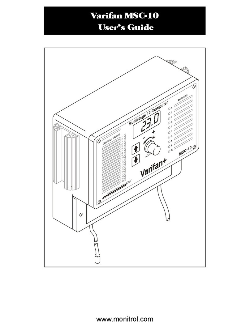
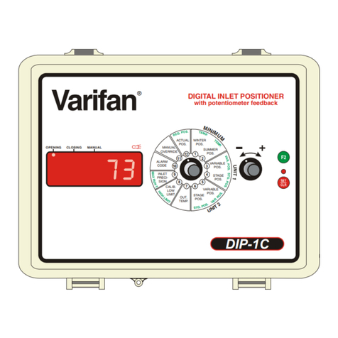
Varifan DIP-1/115 Operation manual

INSTALLATION/
USER’S GUIDE
DIP-1/115
DIP-1/115
ADJUST
+
Compatible
ECS M series
DIGITAL INLET POSITIONER
WITH POTENTIOMETER FEEDBACK
Varifan
®
F2
6
5
1
2
3
4
10
11
7
8
9
12
T
E
M
P.
T
E
MP.
S
.
P.
C
A
L
I
B
.
M
I
N
I
M
U
M
5
4
2
3
1
SUMMER
POS.
WINTER
POS.
ACTUAL
POS.
MANUAL
POS.
START
POS.
START
POS.
END
POS.
END
POS.
POS.
POS.
POS.
EXT.
TEMP.
ALARM
CALIBRATION
MANUAL
CLOSING
OPENING
T
I
M
E
R
23.3
www.monitrol.com

Page 2
DIP-1/115
Although the manufacturer has made every effort
to ensure the accuracy of the information
contained herein, this document is subject to
change without notice due to ongoing product
development.
WARNING AND PRECAUTIONS
Equipment, probe failure, blown fuses and/or
tripped breakers may prove harmful to the
contents of the building. Therefore it is strongly
recommended to install backup devices and alarm
or warning devices. Spare equipment should also
be available at the owner’s site. Equipment
manufactured by the manufacturer is protected
against normal line surges. High surges caused by
thunder storms or power supply equipment may
damage this equipment. For added security
against line voltage surges it is recommended that
surge and noise suppression devices be installed
at the electrical distribution panel. Use of shielded
cable for probes is recommended for protection
against lightning. These devices are available from
most electrical supply distributors.
RECOMMENDATIONS
The manufacturer recommends that all installation
procedures described herein be performed by a
qualified electrician or installation technician.
Further more the manufacturer recommends to
test all the functions and equipment connected to
the DIP, including the alarm system and backup
devices, after installation, after changes to the
installation and every month after that.
Fuse verification and replacement, as well as the
proper setting of control values shall be the
responsibility of the owner of this equipment.
www.monitrol.com

Page 3
TABLE OF CONTENTS
CHAPTER 1 - INTRODUCTION
1. General ........................................................................... 5
1.1 Description ...................................................................... 5
CHAPTER 2 - INSTALLATION
2.1 Unpacking ....................................................................... 7
2.2 Mounting ......................................................................... 7
2.3 Software Setting Switch .................................................. 8
2.4 Connection Procedure .................................................... 8
2.4.1 Input Power ..................................................................... 8
2.4.2 Connecting To The Actuator ........................................... 9
2.4.3 Connecting to ECS-M ..................................................... 9
2.5 Temperature probe ........................................................ 10
2.5.1 Outside Temperature Probe........................................... 10
2.6 Alarm.............................................................................. 10
2.7 Powering Up................................................................... 11
CHAPTER 3 - USER GUIDE
LED Status Window .................................................................... 14
Control Dial ................................................................................. 14
PRIMARY FUNCTIONS
Winter Minimum Position ............................................................ 21
Summer Minimum Position ......................................................... 22
Start Position For The First Stage (unit 1)................................... 23
End Position For The First Stage (unit 1).................................... 24
Start Position For The Second Stage (unit 1) ............................. 25
End Position For The Second Stage (unit 1)............................... 26
Position For The Third Stage (unit 1) .......................................... 27
Position For The Fourth Stage (unit 1)........................................ 28
Position For The Fifth Stage (unit 1) ........................................... 29
Outside Temperature Display ..................................................... 30
Manual Position........................................................................... 31
Actual Position Display................................................................ 32
www.monitrol.com

Page 4
DIP-1/115
SECONDARY FUNCTIONS
Winter Temperature .....................................................................33
Summer Temperature ..................................................................34
Start Position For The First Stage (unit 2)....................................35
End Position For The First Stage (unit 2).....................................36
Start Position For The Second Stage (unit 2) ..............................37
End Position For The Second Stage (unit 2)................................38
Position For The Third Stage (unit 2) ...........................................39
Position For The Fourth Stage (unit 2).........................................40
Position For The Fifth Stage (unit 2) ............................................41
Automatic Calibration ...................................................................42
Timer ........................................................................................43
Static Pressure Display................................................................44
APPENDIX
Error codes...................................................................................47
Troubleshooting ...........................................................................49
Specifications ...............................................................................50
Warranty.......................................................................................51
www.monitrol.com

Page 5
1. GENERAL
This document provides a description of the DIP-1 control
panel, and is organized as follows:
•Introduction
•Installation
•User’s Guide
•Appendix
1.1 DESCRIPTION
Congratulations on the purchase of your DIP-1/115 control.
The DIP-1/115 is specially designed to position a curtain or
air inlet for actuators with 115VAC potentiometer feedback.
The DIP-1/115 provides a full air inlet control.
The DIP-1/115 offers the following features:
•Compatible with 1 or 2 controls of the ECS-M series
•Automatic detection of the ventilation stage
This control allows a minimum positioning or selection for
summer and winter, to avoid abrupt temperature changes.
The air inlet automatically gets positioned when a
ventilation stage (on the ECS-M) is activated, the air inlet
gets proportional positioned between the start and the end
position when the stage is variable. If the stage is
controlled by a relay (single speed stage), the air inlet gets
positioned by stage.
The DIP-1/115 memorizes the highest percentage and
positions the air inlet at its position.
The DIP-1/115 provides you with full control over the air
inlet by using an easy to follow display panel. All
programmable features can be customized to meet your
requirements. The DIP-1/115 keeps you constantly
informed by displaying the status of the air inlet as well as
the actual position.
CHAPTER 1 - INTRODUCTION
www.monitrol.com

Page 6
DIP-1/115
www.monitrol.com

Page 7
Chapter 2 describes the installation of the DIP-1/115
control.
2.1 UNPACKING
Unpack the DIP-1/115 from its box and inspect contents for
damage. Should the contents appear to be damaged,
contact your local distributor for return material procedures.
The package should contain the following standard items:
•1 DIP-1/115 control.
•1 installed outside temperature probe (2004-1K).
•3 cable fasteners or fuse.
•1 Installation/User’s manual.
2.2 MOUNTING
Use a screwdriver to remove the faceplate and the plate of
the power compartment.
The manufacturer recommends that the installation
instructions which follow be adhered to as closely as
possible, and all work be performed by a certified
electrician. Failure to do so may void the warranty!
To limit the unit’s exposure to noxious gases install the
unit in a hallway.
Make certain that the unit is mounted right side up with
the cable entry holes facing down.
The DIP-1/115 will operate in a temperature range of
32ºF - 120ºF (0ºC - 50ºC).
Install the DIP-1/115 not longer the 2 meters from each
ECS.
The enclosure is watertight, but not splash proof or
immersion proof. DO NOT WATER the control. Cover the
control carefully with plastic when cleaning the room.
*It is prohibited to use overhead cables outside the
building.
Mounting hardware is not included with the unit.
CHAPTER 2 - INSTALLATION
www.monitrol.com

Page 8
DIP-1/115
Install mounting screw on wall and hang the unit in place
by sliding the rear mounting hole of the DIP-1/115 over the
screw. Use two more screws to secure the DIP-1/115 in
place using the bottom mounting hole.
2.3 SOFTWARE SETTINGS SWITCH
The switch is located behind the DIP-1/115 faceplate and
adjusts the following options.
Switch 1 Selects between a Fahrenheit or Celsius
display on the DIP-1/115.
Switch 2 Locks / unlocks. All settings are locked while
this switch is off.
Switch 3 One or two ECS-M connected to the DIP-
1/115.
Switch 4 To enable automatic calibration switch 4
must be OFF. When automatic calibration
is done, you must put the switch back
ON return to normal mode.
2.4 CONNECTION PROCEDURE
For the connection procedure which follow, refer to
figure 1.
2.4.1 Input power
Use a screwdriver to remove cable knock-outs for the
installation of cabling to the DIP-1/115.
OFF ON
Fahrenheit
Setting locked
2 Units
Automatic calibration
Celsius
Setting unlocked
1 Unit
Normal operation
OFF ON
Do not apply power to the DIP-1/115, ECS-M and the
actuator until all connections have been completed!
1
2
3
4
www.monitrol.com

Page 9
2.4.2 Connecting to the actuator (figure 1)
•Connect L1 to terminal L of the DIP-1/115.
•Connect N (neutral) to terminal N of the DIP-1/115.
•Connect a wire between terminal OPEN of the
DIP-1/115 and terminal OPEN of the actuator.
•Connect a wire between terminal CLOSE of the
DIP-1/115 and terminal CLOSE of the actuator.
•Connect a wire between terminal COM of the
DIP-1/115 and terminal COM of the actuator.
•Connect a shielded cable between terminal (wiper) of
the potentiometer and terminal (POT) of the DIP-1/115.
•Connect a shielded cable between the potentiometer
and terminal (GNA) of the DIP-1/115.
•Verify jumpers according potentiometer used (figure 3).
The accuracy of the actuator’s positioning depends on the
type of actuator. The positioning is accurate at more or
less 1/8 in (3mm)
2.4.3 Connecting to the ECS-M
•Disconnect power of the ECS-M.
•These cables can extend up to a distance of 6 feet (2
meters).
•Connect one end of the cable to the (SIN), (SCK) and
(GND) terminal of the DIP-1/115 to the ECS-M. (If you
connect only one unit to the DIP-1/115, use terminal
(AUX INPUT 1).
CHAPTER 2 - INSTALLATION
NOTE
It is recommended to use the actuator on the longest
travel time possible to obtain maximum accuracy in
the curtain’s positioning (min. 12 in. or 30 cm).
Remember that a bad connection of the cables / pulley
between the actuator and the curtain influences the
accuracy of the curtain’s positioning.
www.monitrol.com

Page 10
DIP-1/115
2.5 TEMPERATURE PROBE
Outside temperature probes use a “Class II” low voltage
circuit. These cables (AWG#18 min) can measure up to
500 feet (150 meters). Outside temperature probe is
illustrated in figure 2.
2.5.1 Outside temperature probe
Install the outside temperature probe in an area that best reflects the
overall outside temperature.
2.6 ALARM
The DIP-1/115 provides a normally closed and a normally
open dry contact for monitoring communication failures
between the DIP-1/115 and the ECS-M, loss of power
between the DIP-1/115 and the ECS-M and potentiometer
malfunction. This contact may be connected to an alarm
system, or directly to a siren and / or an auto-dialer.
Do the connection according to the normally open (NO) /
normally closed (NC) options illustrated in figure 2.
Use a shielded cable for probes. Connect the shields to
the “SHLD” terminal. Failure to do so may result in
inaccurate readings and inefficient protection against
lightening and electromagnetic fields.
Do not expose outside temperature probes to direct
sunlight !
Momentary power interruptions may trigger false alarms!
To avoid false alarms when the DIP-1 is connected to an
alarm system, install a time delay relay between the
DIP-1/115 and the alarm system.
www.monitrol.com

Page 11
2.7 POWERING UP
Before powering up the DIP-1/115, attach the faceplate to
the casing of the unit using the screws previously
removed.
Set selector knob to position (12).
Upon power up, the unit will test it’s display by briefly
lighting all the segments of it’s LEDs. Make sure that all
segments light up.
Following the LED display test, the unit displays the actual
position of the air inlet.
If the actual position of the air inlet is not displayed or
ER5 comes on, refer to the Troubleshooting section of
this manual.
ADJUSTING THE POTENTIOMETER LIMIT VALUES
In order to function properly, the DIP-1 has to be
manually calibrated the first time it is started. The
initial calibration is done by following these 3 steps:
•Make sure the #4 switch is ON.
•Step 1: Set the DIP-1/115 in manual mode (position
11).
•Step 2: Turn the Adjustor dial to HI and wait for the
motor to stop at least 15 seconds.
•Step 3: Turn the Adjustor dial to LO and wait for the
motor to stop.
It is important to follow those 3 steps to allow the
DIP-1/115 to memorizes the inlet minimum and maximum
positions. They are saved everytime a Lo or Hi position is
reached. Even if the position hasn’t changed, it is still
recorded after 10 seconds or so.
www.monitrol.com

Page 12
DIP-1/115
Fig. 1 Connection between, actuator, ECS-M and DIP-1/115
PROBES
ACTUATOR
UNIT 1 UNIT 2 ALARM
NC
CNO
L
L
N
N
SHLD
POT
PRB
GNA
PWR
GND
GND
GND
OPEN
OPEN
CLOSE
CLOSE
COM
COM
SCK
SCK
SCK
SIN
SIN
SIN
1090 A REV.1
LINE
110VAC~
ACTUATOR
115 V
ECS
Power cut and protection devices in case of overload.
If ER4 is displayed, check if the reading of the potentiometer is lower when
the air inlet is close. (If the value of the POT is higher when the air inlet is
closed, connect the POT wire to the second terminal of the actuator).
1
1
2
2
www.monitrol.com

Page 13
CHAPTER 2 - INSTALLATION
Fig 2.
Probe and Alarm Wiring
Fig 3.
Main Bottom Board: Terminal Block and Fuse Location
F3 F1
T4.00A250V
5X20mm
125mA
www.monitrol.com

Page 14
DIP-1/115
CHAPTER 3 - USER’S GUIDE
The DIP-1/115 front panel shown next features a LED
status window and two control dials that are respectively
used to select a function and adjust a setting.
LED STATUS WINDOW
The LED status window features a 3 digit LED readout for
outside temperature, the display of inlet position and
programmable settings.
In addition, the LED status window displays the operational
status of air inlet, control, potentiometer and alarm via 6
additional LEDS (shown next in LED window). The first
and second LEDs indicate if the air inlet is closing or
opening. The third LED indicate the DIP-1/115 in manual
mode. The fourth LED provides the potentiometer actual
status: if the LED flashes when the actuator is ON, this
means the DIP-1/115 detect an intermittent contact coming
from the potentiometer. Solution: replace the
potentiometer. If the LED flashes while the actuator is
stopped, this means the DIP-1/115 do not detect the
presence of the potentiometer. Solution: verify the wiring
and the potentiometer. The fifth LED indicates when the
auto-calibration is in process, and the sixth indicate an
alarm to lost contact between ECS-M and DIP-1/115.
CONTROL DIALS
The center dial is the Selector dial and is used to select
one of the DIP-1/115’s 12 primary or secondary functions.
The dial located to the right of the Selector is the Adjustor
dial and is used to enter secondary function mode and to
adjust setting of each function.
www.monitrol.com

Page 15
CHAPTER 3 - USER’S GUIDE
ADJUST
+
Compatible
ECS M series
DIP-1
DIGITAL INLET POSITIONER
WITH POTENTIOMETER FEEDBACK
Varifan
®
F2
6
5
1
2
3
4
10
11
7
8
9
12
T
E
M
P.
T
E
MP.
S
.
P.
C
A
L
I
B
.
M
I
N
I
M
U
M
5
4
2
3
1
SUMMER
POS.
WINTER
POS.
ACTUAL
POS.
MANUAL
POS.
START
POS.
START
POS.
END
POS.
END
POS.
POS.
POS.
POS.
EXT.
TEMP.
ALARM
CALIBRATION
MANUAL
CLOSING
OPENING
T
I
M
E
R
50
www.monitrol.com

Page 16
DIP-1/115
The 12 primary functions are:
•1 Winter minimum position
•2 Summer minimum position
•3 Start position, when the first stage begins to operate at
minimum speed (unit 1)
•4 End position, when the first stage runs at its maximum
speed (unit 1)
•5 Start position, when the second stage begins to operate at
minimum speed (unit 1)
•6 End position, when the second stage runs at its maximum
speed (unit 1)
•7 Position, when the third stage begins to operate (unit 1)
•8 Position, when the fourth stage begins to operate (unit 1)
•9 Position, when the fifth stage begins to operate (unit 1)
•10 Exterior temperature display
•11 Manual positioning of the air inlet
•12 Actual position of the air inlet display
Any of these functions is selected by rotating the Selector
dial to the corresponding number and graphical image
printed on the faceplate of the DIP-1/115. When primary
functions 1 through 11 are selected, the LED status
window displays a flashing value. But if it displays 3
horizontal stripes, it means your system doesn’t include
that function. Function 12 displays the actual position of
the air inlet and doesn’t flash.
www.monitrol.com

Page 17
The 12 secondary functions are:
•1 Desired temperature for winter
•2 Desired temperature for summer
•3 Start position, when the first stage begins to operate at
minimum speed (unit 2)
•4 End position, when the first stage runs at its maximum
speed (unit 2)
•5 Start position, when the second stage begins to operate at
minimum speed (unit 2)
•6 End position, when the second stage runs at its maximum
speed (unit 2)
•7 Position, when the third stage begins to operate (unit 2)
•8 Position, when the fourth stage begins to operate (unit 2)
•9 Position, when the fifth stage begins to operate (unit 2)
•10 Automatic calibration
•11 Timer
•12 Static room pressure display during the automatic
calibration
Select any one of these secondary mode functions by:
•rotating the Selector dial to (12)
•rapidly rotating the Adjustor dial back and forth to enter
in secondary mode
•rotating the Selector dial from function (12) to any
other function.
When secondary functions 1 through 11 are selected the
status window displays a flashing value along with a
scrolling LED display. Selection of function 12 removes the
DIP-1/115 from the secondary function mode.
CHAPTER 3 - USER’S GUIDE
www.monitrol.com

Page 18
DIP-1/115
Fig 4.
Typical Application, 2 ECS-M in cascade
F2
6
5
1
2
3
4
10
11
7
8
9
12
T
E
M
P.
T
E
MP.
2
n
d
U
N
I
T
2
nd
U
N
I
T
2
n
d
U
N
I
T
2
n
d
U
N
I
T
2
n
d
U
N
IT
2
n
d
U
N
I
T
TIMER
P
.S
.
C
A
L
I
B
.
SUMMER
POS.
WINTER
POS.
ACTUAL
POS
MANUAL
POS.
START
POS.
START
POS.
END
POS.
END
POS.
POS.
POS.
POS.
EXT.
TEMP.
2
n
d
U
N
IT
www.monitrol.com

Page 19
CHAPTER 3 - USER’S GUIDE
Here is a typical application (figure 4). In this example, an
ECS-4M and an ECS-5M in cascade are illustrated to
demonstrate the complete operation of the DIP-1/115.
Here is a description of this installation:
WINTER POS, SUMMER POS: Functions 1 & 2 allow
setting of a minimum opening position (in percentage) for
each season.
TEMP.: Functions 1 & 2 secondary mode allow setting of
temperature for winter and summer. When outside
temperature is between 0ºC(20°F) and 20ºC (70°F) and
none of the ventilation stages are activated, the air inlet
varies between the minimum winter position and the
minimum summer position.
When temperature reaches 20°C (70°F) (stage 1). The
ECS-5M’s first fan begins to operate, the air inlet opens at
23% and varies to 30% as the fan’s speed increases. (In
fig. 4, the ECS-5M’s first fan is in continual ventilation, “- - -”
is displayed at position 3 and the air inlet varies between
the minimum position (summer, winter), and the end
position for the first stage).
When the temperature reaches 22ºC (74°F) (stage 2).
The ECS-5M’s second fan begins to operate, the air inlet
opens at 37% and varies to 44% at the same time as the
fan’s speed accelerates.
When the temperature reaches 25ºC (78°F) (stage 3).
The ECS-4M’s first fan begins to operate, the air inlet
opens at 51% and varies to 58% at the same time as the
fan’s speed accelerates.
When the temperature reaches 27ºC (82°F) (stage 4).
The ECS-4M’s second fan begins to operate, the air inlet
opens at 65% and varies to 72% at the same time as the
fan’s speed accelerates.
When the temperature reaches 28ºC (84°F)(stage 5).
The ECS-5M’s third fan begins to operate, the air inlet
opens at 79%.
www.monitrol.com

Page 20
DIP-1/115
When the temperature reaches 29ºC (86°F) (stage 6).
The ECS-5M’s fourth fan begins to operate, the air inlet
opens at 86%.
When the temperature reaches 30ºC (88°F) (stage 7).
The ECS-4M’ third fan begins to operate, the air inlet opens
at 93%.
When the temperature reaches 31ºC (90°F) (stage 8).
The ECS-4M’s fourth fan begins to operate, the air inlet
opens at 100%.
The DIP-1 displays 3 horizontal stripes “- - -” to position 9
(primary and secondary functions) because the fifth
ventilation stage is not available on the units.
Refer to the examples on the bottom of the next pages for
more details on this installation.
www.monitrol.com
Table of contents
Other Varifan Control System manuals

Varifan
Varifan SVIM-1LE User manual

Varifan
Varifan IC-68ND User manual

Varifan
Varifan MSC-10 User manual

Varifan
Varifan ECS-1M User manual

Varifan
Varifan VPM-1 User manual

Varifan
Varifan CM10-2 User manual
Varifan
Varifan CPS-3M User manual

Varifan
Varifan MST-5C User manual

Varifan
Varifan ECS 5M User manual
Varifan
Varifan CPS-2C Operation manual
Popular Control System manuals by other brands

HEIDENHAIN
HEIDENHAIN LIP 471R Mounting instructions

Steril-Aire
Steril-Aire ESE 1 Series Installation and operation instructions

Quilo
Quilo QK-CT219500 Instructions for installation, use and maintenance

Starrett
Starrett AVR200 user guide

Hioth
Hioth CAP-HOMEY Quick install manual

LLURIA
LLURIA DE-5-DMX-6A quick start guide