manuals.online logo
Brands
  1. Home
  2. •
  3. Brands
  4. •
  5. Minolta
  6. •
  7. Measuring Instrument
  8. •
  9. Minolta CS-100A Use and care manual

Minolta CS-100A Use and care manual

CHROMA METER CS-100A
- Communication Manual -
SAFETY PRECAUTIONS
Always observe the following precautions and operate the unit correctly. After you have
read this manual, keep it in a safe place where it can be referred to anytime a question
arises.
CAUTION
Safety Symbols
The following symbols are used in this manual prevent accidents which may occur
as result of incorrect use of the instrument.
This indicates a sentence regarding safety warning or note.
Read the sentence carefully to ensure safe and correct use.
This indicates an instruction for an operation.
Always follow the instruction.
Before using this system, read this manual thoroughly as well as the instruction
manuals of the Chroma Meter and personal computer.
(Failure to observe the precautions and operations as described in
this manual may result in personal in ury or damage to the unit.)
CONTENTS
Connection to personal computer ...................... 1
<Caution related to connection> .............................. 1
<Data output terminal> ....................................... 1
<Connection for RS-232C two-way communications> .............. 3
<Communication parameters> ................................... 3
Setting to RS-232C mode .............................. 4
<Setting procedure> .......................................... 4
Command list ......................................... 4
Notes on RS-232C mode ................................ 5
Delimiter code ....................................... 6
Error chec code ..................................... 6
Explanation of each command .......................... 7
Memory and recall of setting data ................... 14
Relation of display and output data ................. 15
Examples of data communication ...................... 16
INTRODUCTION
This manual explains RS-232C two-way communications function of the chroma meter
CS-100A.
In case to use the ata output function succee e from the former mo el of CS-100,
please refer to the instruction manual of CS-100A.
1
Connection to personal computer
Use RS-232C connecting cable (optional accessory LS-A12) to connect
to a personal computer.
<Caution relate to connection>
Connect the connector to the proper direction securely.
Always turn off the power of both this product and the personal computer
before carrying out the connection.
Remove the connection cord always holding the plug or the connector. And
do not pull or forcibly bend the cord.
Do not touch, stain or apply unreasonable force to the terminal part of the
connector.
Arrange the cord with extra length. If there is not sufficient extra
length, it may cause connection failure or disconnection.
<Data output terminal>
RP 7- 3RA- 2SD made
by Hirose is used
for the connector
for data output of
this product.
Connect and use RP 7-
3P- 2PC connector
made by Hirose.
Absolute maximum rating of output transistor
iTa 25CDTC124XUA, made by Ro mj
V CEO 50V Ic 100mA
V CBO 40V Pc 200mW
2
Each pin of igital output terminal
Pin : Ground (GND)
Pin 2: Ground (GND)
Pin 3: ----
External equipment condition signal input. Use it OPEN (Busy in)
Pin 4: RTS output
Directly connects to the CTS terminal of the personal computer at the
time of two-way communications by RS-232C.
Outputted at the voltage level of about }0V.
Pin 5: External power input
Positive electrode of power when supplying power from outside. Pin or
pin 2 is the ground. Use the power of 8 - 2 VDC, 00mA or more.
Pin 6: CTS input terminal
CTS input
Directly connects to the RTS terminal of the personal computer at the time
of two-way communications by RS-232C.
Pin 7: TxD output
Directly connects to the RxD terminal of the personal computer at the time
of two-way communications by RS-232C.
Outputted at the voltage level of about }0V.
Pin 8: Measured value serial output
Use it OPEN.
Pin 9: RxD input
Directly connects to the TxD terminal of the personal computer at the time
of two-way communications by RS-232C.
Pin 0: Synchronous clock output
Use it OPEN.
Pin : External measuring request signal input
Use it OPEN.
Pin 2: Internal supply power output
Use it OPEN.
@Pins 3,8, 0, , 2 are necessary terminals when succeeding to use the external
output function of the former model CS- 00. Use them OPEN in case to use the
RS-232C communication mode. (Refer to the instruction manual of the main body
version.)
3
<Connection when RS-232C two-way communications>
This product side@@@@@@@@@@@@@@@@@ Personal computer side
GND ( )or(2)pin \\\\\\\\\\\\\\\ SG
RTS output (4)pin \\\\\\\\\\\\\\\ CTS
CTS input (6)pin \\\\\\\\\\\\\\\ RTS
TxD output (7)pin \\\\\\\\\\\\\\\ RxD
RxD input (9)pin \\\\\\\\\\\\\\\ TxD
<Communication parameters>
Set the parameters of the host computer following the RS-232C communication
parameters of this product.
EBaud rate : 4800
EParity : EVEN
EData length : 7bits
EStop bit : 2bits
4
Setting to RS-232C mode
Carry out the following settings to communicate connecting this
pro uct an a personal computer.
<Setting proce ure>
.Check the power is off.
2.Turn on the power switch with the F key of this
product kept pressed.
3.The letter of "C" is displayed in the right bottom
corner of the external display.
It is set to the RS-232C two-way communications mode.
Command list
MES : Following the mode setting, measures one time
Displays the measured value and outputs from the RS-232C terminal.
MDS : Carries out various mode settings.
CLE : Carries out the memory clear action.
RCR : Recalculates according to the mode setting and outputs the calcu-
lated result from the RS terminal.
TDR : Outputs the target value for measuring color difference memorized in
the main body from the RS terminal.
UCR : Outputs the standard value for measuring user calibration standard
memorized in the main body from the RS terminal.
TDS : Memorizes the measured value held by the main body as the target
value for measuring color difference in the main body.
TDW : Receives the target value for measuring color difference from the RS
terminal and memorizes in the main body.
UCW : Receives the standard value for measuring user calibration standard
from the RS terminal and memorizes in the main body.
>
5
Notes on RS-232C mode
EIn case to use in RS-232C two-way communications mode, it is recommended to
carry out OPEN and CLOSE of RS port before or after transmitting one command.
In case to use in RS-232C two-way communications mode, the consumption
current increases comparing to the normal use.
Especially if connected with the RS port of the personal computer side OPEN,
electric current is consumed even if communication is not carried out, so pay
attention.
EWhen RS-232C communication mode, none of the SW other than the power SW is
accepted.
EDoes not carry out printer output.
EActs as command input ¨measurement ¨data output.
EThe output timing is the same as the serial data output.
EThe communication request in the timing affecting the time control (during
measurement) is not accepted.
EWhen the next character or delimiter dose not come even after 5 seconds or
more at the time of receiving a command, send back error (ER00) and drops out
of the treatment.
EWhen about to start the data output but the personal computer is not ready to
receive the data, it become time out after 5 seconds.
EWhen RS-232C communication mode, C is displayed in the right bottom of the
external LCD.
6
Delimiter code
EWhen the above-mentioned command (+ data) + delimiter is inputted from the
control side, this product acts corresponding to the command and consecu-
tively outputs the error check code (+ data) + delimiter.
EThe delimiter is CR + LF and the break point of the data is a comma.
EThe input and output is carried out with a format of fixed length determined
for each command.
Error check code
EThere are kinds of error check codes as shown below.
OK00 : Normal operation
OK : Chromaticity measuring range over (same as  E0 display)
OK 2 : Luminance display range over (same as E9 display)
OK 3 : Luminance display range under (same as flickering display)
ER00 : Command error
(A command other than above-mentioned command is inputted, out of the
parameter setting range)
ER0 : Setting error (same as E display)
ER : Memory value error (same as E display)
ER 0 : Luminance and chromaticity measuring range over (same as E0 display)
ER 2 : Luminance display range, chromaticity display range simultaneous
over (same as E9, E8 display)
ER 9 : Display range over (same as E9 display)
ER20 : EEPROM error (same as E2 display)
(the value of the protect area of EEPROM is broken, cannot access
EEPROM, etc.)
ER30 : Battery out
(The power voltage same as B0 display is lower than BC voltage.)
7
Explanation of each command
In" " of the format of the control side (personal computer side) Ë this
product (CS- 00A), 0 - 9, and ".(period)", " (space)" comes in.
The number of " " means the number of input letters.
In case to input fewer number of letters than the specified number of
letters, input space as many times as the shortage letters and them input
the numeric value.
[Example]In case to input " 2.4" into the format of "  ", input
"¢¢ 2.4" (¢ is a space.).
In" " of the format of this product side (CS- 00A) Ë the control side
(personal computer), 0 - 9, and ".(period)", " (space)" comes in.
The number of " " means the number of letters. Therefore, in case to
output the numeric value of " 2.4" to the format of "  ", the
letter string of " ¢¢ 2.4" (¢ is a space.) is outputted.
In the notation, specifying delimiter is omitted.
The following errors that are possible to occur at any time are not clearly
specified in the explanation. When these errors occur, only the check
command corresponding to each error is outputted in case of the output from
[this product Ë control side] in the explanation.
@¨ "ER00" cccc Command error
A command other than the above-mentioned command is
inputted. Out of the parameter setting range
@¨ "ER " cccc Memory value error (same as E display)
@¨ "ER20" cccc EEPROM error
The value in the protect area of EEPROM is broken,
cannot access EEPROM, etc.
@¨ "ER30" cccc Battery out
Same as B0 display. The power voltage is lower than
the BC voltage.
8
Command MES
Function @Following the mode setting, measures one time.
@Outputs the measured value.
Control side Ëthis product format
MES
This product Ëcontrol side format
@When normal measurement
"O 00, } ,}D ,}D "
@When luminance and chromaticity measuring range over
(same as E0 display)
"ER10"
@
When chromaticity measuring range over (same as  E0 display)
"O 11, } ,}D0000, }D0000"
@When luminance display range over (same as E9 display)
"O 12, |999999, }D ,}D "
@When display out of the range display and out of the
measuring range display (over, chromaticity only) simul-
taneous occurrence (same as E9, E0 display)
"ER12"
@
When luminance display range under (same as flickering display)
"O 13, } ,}D ,}D "
Control sideËthis product format details
Command only
This productËcontrol side format details
@When normal measurement
Following the error check command, outputs the luminance
value Y (or luminance difference cY), chromaticity x (or,
chromaticity difference cx), chromaticity y (or chromatic-
ity difference cy).
@
When luminance and chromaticity measuring range over (same as E0 display)
Outputs only error check command.
@
When chromaticity measuring range over(same as  E0 display)
Following the error check command, outputs y luminance
value Y (or luminance difference cY), error constant.
@When luminance display range over (same as E9 display)
Following the error check command, outputs error constant
chromaticity x (or chromaticity difference cx), chromatic-
ity y (or chromaticity difference cy).
@When display out of the range display and out of the
measuring range display (over, chromaticity only) simul-
taneous occurrence. Outputs only error check command.
@
When luminance display range under (same as flickering display)
Following the error check command "O 13", outputs luminance
value Y (or luminance difference cY), chromaticity x (or
chromaticity difference cx), chromaticity y (or chromatic-
ity difference cy).
9
Command MDS
Function Carries out various mode settings
Control side Ëthis product format
"MDS,  "
This product Ëcontrol side format
Only error check command
Control sideËthis product format details
In the 2-digit parameter following the command code, the following
numeric value comes in according to the measuring mode to set.

MINOLTA calibration standard mode
"00"
Same as the calibration switch [PRESET] side.
@Arbitrary calibration standard mode "01"
Same as the calibration switch [VARI] side.
@Color measuring mode "04"
Same as the measuring mode switch [ABS] side.
@Color difference measuring mode "05"
Same as the measuring mode switch [DIFF].
@Measuring response time 100 msec. "06"
Same as the response switch [FAST] side.
@Measuring response time 400 msec. "07"
Same as the response switch [SLOW] side.
This productËcontrol side format details
Only error check command
Command RCR
Function @Recalculates according to the mode setting and outputs the
calculated result from the RS terminal.
@The measured value is held, or held by this product.
Depending on the condition of the measured value, an error
may occur.
When luminance and chromaticity setting range over
(same as E0 display)
When chromaticity measuring range over
(same as  E0 display)
When luminance display range over (same as E9 display)
In case that the measured value is not held
(same as E display)
Control side Ëthis product format
"RCR"
To the Next page
10
This product Ëcontrol side format
@When normal measurement
"O 00, } ,}D ,}D "
@When luminance and chromaticity measuring range over
(same as E0 display)
"ER10"
@
When chromaticity measuring range over (same as  E0 display)
"O 11, } ,}D0000, }D0000"
@When luminance display range over (same as E9 display)
"O 12, |999999, }D ,}D "
@Display out of the range display and out of the measuring
range display (over, chromaticity only) simultaneous oc-
currence (same as E9, E0 display)
"ER12"
@
In case that the measured value is not held (same as E display)
"ER01"
@
When luminance display range under (same as flickering display)
"O 13, } ,}D ,}D "
Control sideËthis product format details
Command only
This productËcontrol side format details
@When normal measurement
Following the error check command, outputs luminance value
Y (or luminance difference cY), chromaticity x (or, chro-
maticity difference cx), chromaticity y (or chromaticity
difference cy).
@
When luminance and chromaticity measuring range over (same as E0 display)
Outputs only error check command.
@When chromaticity measuring range over
(same as  E0 display)
Following the error check command, outputs luminance value
Y (or luminance difference cY), error constant.
@When luminance display range over (same as E9 display)
Following the error check command, outputs error constant
chromaticity x (or chromaticity difference cx), chroma-
ticity y (or chromaticity difference cy).
@When display out of the range display and out of the measur-
ing range display (over, chromaticity only) simultaneous
occurrence. Outputs only error check command.
@When the measured value is not held (same as E display)
Outputs only error check command.
@When luminance display range under (same as flickering display)
Following the error check command "O 13", outputs luminance
value Y (or luminance difference cY), chromaticity x (or
chromaticity difference cx), chromaticity y (or chromatic-
ity difference cy).
11
Command TDR
Function Outputs the target value for measuring color difference memo-
rized in the main body.
Control side Ëthis product format
"TDR"
This product Ëcontrol side format
"O 00,  ,D ,D "
Control sideËthis product format details
Command only
This productËcontrol side format details
@
Following the error check command, outputs target luminance value Y,
target chromaticity value x, target chromaticity value y.
Command UCR
Function @Outputs the standard value for measuring user calibration
standard memorized in the main body.
Control side Ëthis product format
"UCR"
This product Ëcontrol side format
"O 00,  ,D ,D "
Control sideËthis product format details
Command only
This productËcontrol side format details
@
Following the error check command, outputs luminance standard value Y,
chromaticity standard value x, chromaticity standard value y.
Command TDS
Function @Memorizes the measured value held in the main body as the target
value for measuring color difference in the main body.
@
Depending on whether the measured value is held or on the condition
of the measured value held in this product, an error may occur.
ËIn case not to be calculated and memorized [normally]
When luminance and chromaticity measuring range over (same as E0 display)
When chromaticity measuring range over (same as  E0 display)
When luminance display range over (same as E9 display)
In case that the measured value is not held (same as E display)
Control side Ëthis product format
"TDS"
This product Ëcontrol side format
@In case to be calculated and memorized normally
"O 00"
@In case not to be calculated and memorizes normally
"ER01"
Control sideËthis product format details
Following the command, outputs target luminance value Y, target
chromaticity value x, target chromaticity value y.
This productËcontrol side format details
@In case to be calculated and memorized normally
Outputs the error check command only.
@In case not to be calculated and memorizes normally
Outputs the error check command "ER01".
12
Command TDW
Function @Receives the target value for measuring color difference
and memorizes in the main body.
(On this product side, the fourth digit is rounded off
because the display valid number of is 3-digit.)
@The unit is recognized with the unit set on this product side.
Control side Ëthis product format
"TDW,  ,D ,D "
This product Ëcontrol side format
@In case to be calculated and memorized normally
"O 00"
@In case not to be calculated and memorizes normally
"ER01"
Control sideËthis product format details
Following the command, outputs target luminance value Y, target
chromaticity value x, target chromaticity value y.
This productËcontrol side format details
Error check command only
13
Command UCW
Function @Receives the standard value for measuring user calibration
standard and memorizes in the main body.
@
Calculate the coefficient for user calibration standard and memorizes.
(On this product side, the fourth digit is rounded off
because the display valid number of digit is 3-digit.)
@The unit is recognized with the unit set on this product side.
@
Resulting in error when the command is sent in the following condition.
ËIn case not to be calculated and memorizes normally
Condition that the measured value is not held in this product.
Condition that the measured value is the measuring range over.
Condition that the measured value is the display range over.
Condition that the measured value Y is "0".
Condition that the luminance standard value Y is "0".
Condition that the chromaticity standard value y is "0".
Control side Ëthis product format
"UCW,  ,D ,D "
This product Ëcontrol side format
@In case to be calculated and memorized normally
"O 00"
@In case not to be calculated and memorizes normally
"ER01"
Control sideËthis product format details
@Following the command, outputs luminance standard value Y,
chromaticity standard value x, chromaticity standard value y.
This productËcontrol side format details
@In case to be calculated and memorized normally
Outputs the error check command only.
@In case not to be calculated and memorizes normally
Outputs the error check command "ER01".
Command CLE
Function @Carries out memory clear.
Clear of the color difference standard color data, the
arbitrary calibration standard data.
Control side Ëthis product format
"CLE"
This product Ëcontrol side format
"O 00"
Control sideËthis product format details
Outputs command only
This productËcontrol side format details
Outputs error check command only.
14
Memory and recall of set data
In the RS mode the color difference target data and the user calibration
standard data can be inputted and outputted in valid numeral of 4 digits.
In case to recall the set value memorized in the RS mode in the normal
measuring mode, the fourth digit of the valid numeral is rounded off and
displayed in 3 digits.
(The valid numeral up to 4 digits is used for calculation.)
In case to memorize the color difference target data and the user calibra-
tion standard data in the normal mode, [0] comes instead of the fourth
digit of the valid numeral.
Therefore, in case to read out the set data memorized in the normal mode,
the fourth digit becomes always [0].
15
Relation of display and output data
1. Relation of isplay an output ata
This product has 4-digit data of valid number of digits for all Y,
x, y inside and this 4-digit data are outputted.
(As to Y, in numeric value of lower than 0, numeric value up to
third decimal place is dealt.)
The display is 3 digits of valid number of digits, and displays
after [cutting off] the fourth digit of the internal data.
In the internal calculation, the valid number of digit is 4 digits by
rounding off. At this point, error of } digit may be included.
Internal data, or relation of output data and display is as follows.
Yxy
Internal data 10.79 0.3346 0.3021
Display 10.7 0.334 0.302
2. Treatment of the vali igit in the color ifference measurement.
(Difference of internal calculation an ata output, isplay)
2.1 As to calculation of difference of Y value (cc
cc
cY) in the color difference measurement
In the color difference calculation in this product, the output digit
number of calculated result of cY changes depending on the size of
the Y value of the measured value and Y value of the target color.
The lowest valid digit of the color difference calculation result is
worked out matched with the lowest valid digit of bigger one of
either Y value of the measured value or Y value of the target color.
(At this point, the numeral is rounded off.)
The relation of Y value of the measured value, Y value of the target
color, internal data and display is as follows.
2.2
As to calculation of difference of chromaticity cc
cc
cx, cc
cc
cy in the color difference measurement
As to the difference of the chromaticity cx value, cy value, up
to the fourth decimal place of the fixed decimal form is worked out.
Y value of the measured
value (Internal data)
Y value of the target
color (Internal data)
Original color difference
calculation valueicYj
Internal data
Display
Calculation example 1
Pattern that the valid
digit does not change.
Calculation example 2
Pattern that the valid
digit decreases.
Calculation example 3
Case(1)that the digit of the measured value
and the standard value are different
Calculation example 4
Case(2)that the digit of the measured value
and the target value are different
234.5 100.0 10240 1.000
100.0 102.3 293.4 10000
134.5 -2.3 9946.6 -9999
134.5 -2.3 9950 -10000
The first decimal place
is the lowest valid digit.
Therefore, the valid
digit number of the in-
ternal data is 2 digits.
The second digit (ten digits) is
the lowest valid digit, so the
first digit is rounded off and
the valid number of digit of the
internal data is 3 digits.
The second digit (ten digits) is
the lowest valid digit, so the
first digit is rounded off and
the valid number of digit of the
internal data is 3 digits.
134 -2 9900 -10000
16
Example of data communication
Treatment when reaceiving MES (1 time measurement comman )

Other Minolta Measuring Instrument manuals
Minolta REGIUS 190 User manual

Minolta

Minolta REGIUS 190 User manual
Minolta FLASHMETER VI - PART 2 User manual

Minolta

Minolta FLASHMETER VI - PART 2 User manual

Minolta AUTOMETER III - PART 3 User manual

Minolta

Minolta AUTOMETER III - PART 3 User manual

Minolta FLASH METER VI User manual

Minolta

Minolta FLASH METER VI User manual

Minolta CL-200 User manual

Minolta

Minolta CL-200 User manual

Minolta AUTO METER IIIF - PART 1 User manual

Minolta

Minolta AUTO METER IIIF - PART 1 User manual

Minolta AUTO METER IIIF - PART 2 User manual

Minolta

Minolta AUTO METER IIIF - PART 2 User manual

Minolta FLASH METER IV - PART 2 User manual

Minolta

Minolta FLASH METER IV - PART 2 User manual

Minolta CA-100PLUS - User manual

Minolta

Minolta CA-100PLUS - User manual

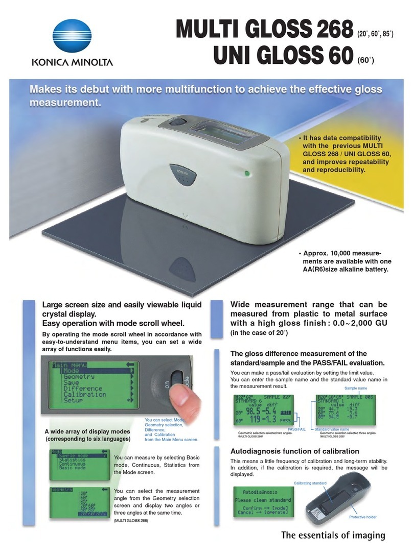
Minolta MULTI GLOSS 268 User manual

Minolta

Minolta MULTI GLOSS 268 User manual

Minolta Auto Meter IV F User manual

Minolta

Minolta Auto Meter IV F User manual

Minolta CR-400 - User manual

Minolta

Minolta CR-400 - User manual

Minolta AUTOMETER VF - PART 3 User manual

Minolta

Minolta AUTOMETER VF - PART 3 User manual

Minolta SPOTMETER F - IR REMOTE CONTRO LRC-3 User manual

Minolta

Minolta SPOTMETER F - IR REMOTE CONTRO LRC-3 User manual

Minolta SPOTMETER M - IR REMOTE CONTRO LRC-3 User manual
Minolta

Minolta SPOTMETER M - IR REMOTE CONTRO LRC-3 User manual

Minolta FLASH METER III - PART 2 User manual

Minolta

Minolta FLASH METER III - PART 2 User manual

Minolta Auto Meter IV F User manual

Minolta

Minolta Auto Meter IV F User manual

Minolta FLASH METER V - PART 2 User manual

Minolta

Minolta FLASH METER V - PART 2 User manual

Minolta AUTO METER IIIF - PART 3 User manual

Minolta

Minolta AUTO METER IIIF - PART 3 User manual

Minolta Auto Meter IV F User manual

Minolta

Minolta Auto Meter IV F User manual

Minolta AUTO METER IIIF - PART 2 User manual
Minolta

Minolta AUTO METER IIIF - PART 2 User manual

Minolta Flash meter IV User manual

Minolta

Minolta Flash meter IV User manual
Minolta AUTO METER IIIF - PART 2 User manual

Minolta

Minolta AUTO METER IIIF - PART 2 User manual

Minolta AUTO METER IIIF - PART 3 User manual
Minolta

Minolta AUTO METER IIIF - PART 3 User manual

Popular Measuring Instrument manuals by other brands

LEM Analyst 2050 operating instructions

LEM

LEM Analyst 2050 operating instructions

KJ Instrument KJ6013 Operation manual

KJ Instrument

KJ Instrument KJ6013 Operation manual

GE EPM 5300 instruction manual

GE

GE EPM 5300 instruction manual

CHOWIS dp viso+ user manual

CHOWIS

CHOWIS dp viso+ user manual

Keysight PNA-X N5244A Service guide

Keysight

Keysight PNA-X N5244A Service guide

Avery Weigh-Tronix ZT350 User instructions

Avery Weigh-Tronix

Avery Weigh-Tronix ZT350 User instructions

dynasonics UFX operating instructions

dynasonics

dynasonics UFX operating instructions

jwLabs A3 Instruction manuals

jwLabs

jwLabs A3 Instruction manuals

Keysight E4990A troubleshooting guide

Keysight

Keysight E4990A troubleshooting guide

Transducer Techniques SSI Operator's manual

Transducer Techniques

Transducer Techniques SSI Operator's manual

Teledyne Lecroy Everywhereyoulook DL05-HCM Operator's manual

Teledyne Lecroy

Teledyne Lecroy Everywhereyoulook DL05-HCM Operator's manual

amc VIBRO AV MONITOR 1002DX user manual

amc VIBRO

amc VIBRO AV MONITOR 1002DX user manual

Primes BM+ 60 Original instructions

Primes

Primes BM+ 60 Original instructions

Carrel & Carrel C400 Series quick start guide

Carrel & Carrel

Carrel & Carrel C400 Series quick start guide

Primes PowerMonitor PM Series Original instructions

Primes

Primes PowerMonitor PM Series Original instructions

GW Instek PEL-3000 Series user manual

GW Instek

GW Instek PEL-3000 Series user manual

Milwaukee MW101 user manual

Milwaukee

Milwaukee MW101 user manual

FMS RTM MP EMGZ482T.MP.24VDC Operation manual

FMS

FMS RTM MP EMGZ482T.MP.24VDC Operation manual

manuals.online logo
manuals.online logoBrands
  • About & Mission
  • Contact us
  • Privacy Policy
  • Terms and Conditions

Copyright 2025 Manuals.Online. All Rights Reserved.