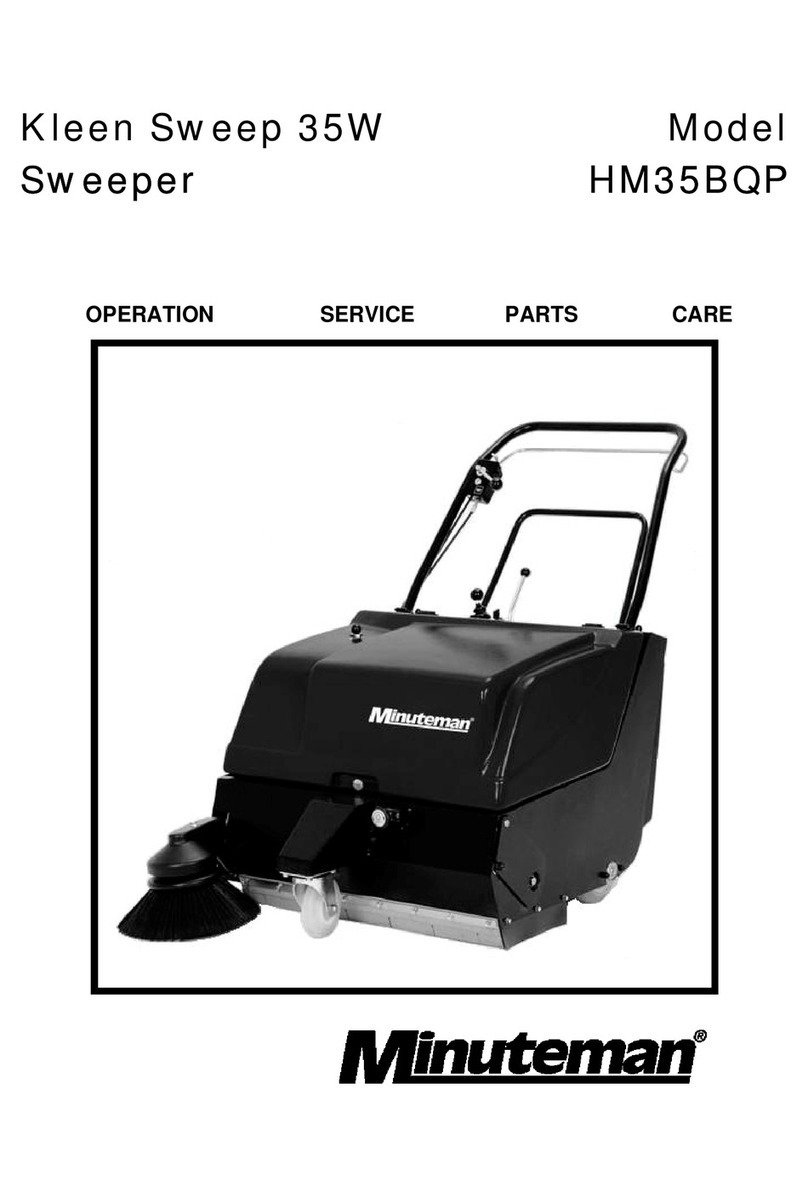
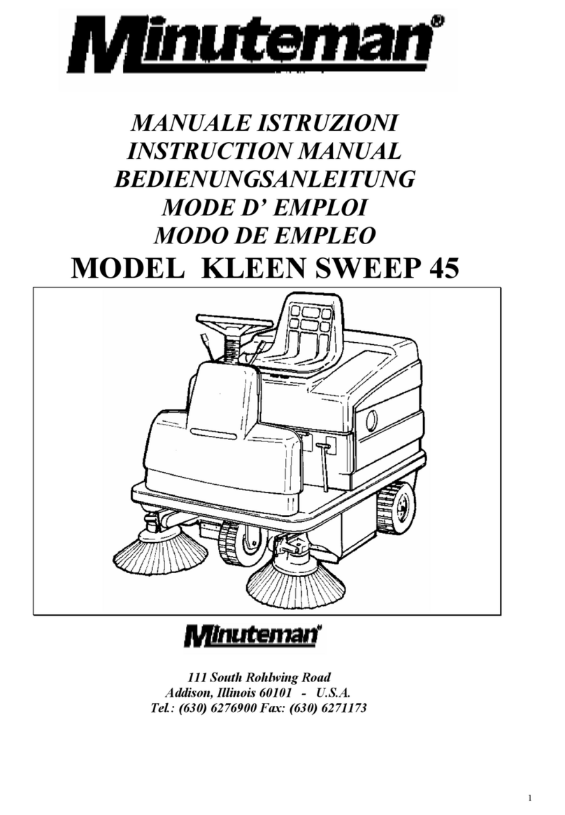
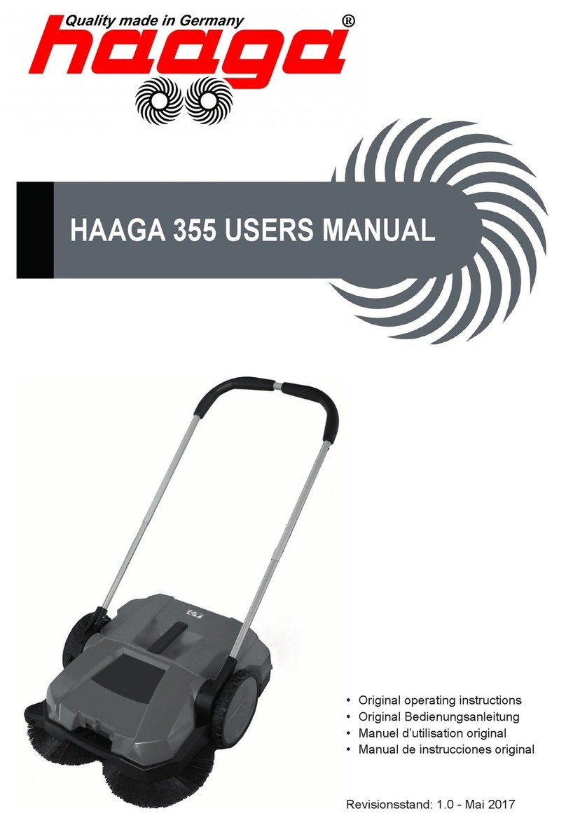
Minuteman Kleen Sweep 35 User manual

TABLE OF CONTENTS
Page
Safety Instructions ............................................ 1
Electrical Requirements ................................... 2
Control Panel Identification .............................. 3 - 5
Operating Instructions ...................................... 6
Maintenance of Machine .................................. 7
Main Components ............................................ 8 - 21
Wiring Diagram ................................................ 22 - 23


1
IMPORTANT SAFETY INSTRUCTIONS
CAUTION
Operators must read and understand this manual before operating or maintaining
this equipment.
• Keep hands and feet clear of moving parts while machine is in operation.
• All switches must be in the “OFF” position when charging batteries.
• Electrical motors and components can cause an explosion when operated near explosive
materials or vapors. Do not operate this machine near flammablematerials such as solvents,
thinners, fuels, grain dusts, etc.
• Make sure all switches are turned “OFF” and battery connections are removed before performing
any maintenance procedures.
• Store or park this machine on a level surface only.
• These machines are designed for level floor operation only. DO NOT OPERATE on ramps or
inclines.
• Battery acid can cause burns. When working on or around batteries, wear protective clothing
and safety glasses. Remove metal jewelry. Do not lay tools or metal objects on top of batteries.
Charging batteries generates explosive gases. DO NOT CHARGE BATTERIES WHEN OPEN
FLAMES OR SPARKS ARE PRESENT. DO NOT SMOKE. Make sure the charger is turned off
before disconnecting it from the batteries. Charge the batteries in a well-ventilated area.
Maintenance and repairs must be performed by authorized personnel.
SAVE THESE INSTRUCTIONS
2
ELECTRICAL REQUIREMENTS:
This piece of equipment operates on 12 Volts DC.
BATTERY REQUIREMENTS:
1 x 12V 185AH P/N 956709
BATTERY SERVICE AND INSTALLATION:
* Warning: Battery acid can cause burns. When working on or around batteries, wear protective
clothing and safety glasses. Remove metal jewelry. Do not lay tools or metal objects on top of
batteries.
BATTERY INSTALLATION:
1. Install battery as shown in figure 1 below.
CHARGING OF BATTERIES:
Charging of batteries generates explosive gases. DO NOT CHARGE BATTERIES WHEN OPEN
FLAMES OR SPARKS ARE PRESENT. DO NOT SMOKE. Make sure the charger is turned off
before disconnecting it from the batteries. Charge the batteries in a well-ventilated area. Fluid
levels should be checked before and after charging and maintained at the proper levels.

3
Main broom raise and lower lever.
Forward travel speed control, depressing handle towards operator increases forward speed
moving lever fully forward sets parking brake.
On/Off switch 1= On, 0 = Off
Wet pickup bypass/filter shaker
Side broom raise/lower
Emergency battery disconnect
Battery condition/elapsed time
Optional key switch 1 = On, 0 = Off
Operate with caution when sweeping or transporting near stairs.
This machine not intended to be used on ramps or inclines.
Read repair manual before servicing or repair.
Read instruction manual before operating this piece of equipment.
This symbol signifies warnings about operator safety.

4
OPERATING CONTROLS
1. Emergency Stop Switch
2. Battery Condition Gauge
3. Key Switch (optional)
4. Main Broom Lift Control
5. Forward Speed Control/Parking Brake Lever
6. Power Switch

5
CIRCUIT BREAKER LOCATION
7. Vacuum Interrupt/Filter Cleaning Control
8. Side Broom Lift Control
9. Side Broom Motor Circuit Breaker
10. Main Broom Motor Circuit Breaker
11. Cup Holder/Battery Inspection Access Panel
12. Battery Charging Connector

6
OPERATION
This equipment contains front and rear cover safety interlocs. This equipment will not operate if
covers are not closed and latched in place.
The side broom when lowered ref. lever 8 page 4 will automatically turn on. The side broom
sweeps along curbs and edges, moving dirt and debris into the sweeping path of the main broom.
The main broom is lowered by lever #4 page 4 for sweeping. The engagement of the lever in the
second upmost raised position is for sweeping low cut closed loop type commercial carpet. Fully
raised position if for transport.
Vacuumed dust control lever ref. lever 7 page 4, when sweeping wet areas or wet garbage also
during transport of the machine from place to place. This lever should be in the raised position.
To shake dust from the panel filter this lever should be raised and released several times to
shake dust from the filter into the hopper. During normal operation the lever should be in the
lowered position.

7
MAIN BROOM ADJUSTMENT
The height of the broom can be adjusted by loosening nut (1) removing cotter pin (2) and removing
clevis pin (3). Clockwise rotation of yoke (4) will decrease brush contact, counterclockwise will
increase.
HOPPER
To empty hopper. Slide hopper out
from side of machine as shown.

8
Parts List
Item Part No. Qty. Description
1 361228 1 Rear Tray
2 827666 8 Rivet
3 711114 8 8-32 x .5 A Point Screw
4 450207 4 Latch
5 833436 1 Tilt Cable ACS
6 712536 5 SCR-MCH 10-24 x .62 SS
7 711373 4 Nut, Hex 1/4-20 Nyloc
8 710587 2 1/4-20 x 1.5 Flat Head Screw
9 712319 2 .31 x .78 Finish Washer
10 711505 4 Flat Washer 1/4
11 715183 1 Decal, Instruction
12 712638 5 Nut, Hex 10-24 Nyloc SS
13 711501 8 Washer, #6
14 361286 2 Cable Clip 1/8
15 250040 1 Spring, Extension SS .25 x 8

9
Parts List
Item Part No. Qty. Description
1 361000 1 Front Cover
2 361267 1 Stiffener, Front
3 828893 8 Pop Rivet
4 361263 1 Pocket Pull
5 361227 1 Switch Bracket
6 710180 2 SCR-MCH 1/4-20 x .75
7 711373 2 Nut-Hex 1/4-20 Nyloc
Parts List
Item Part No. Qty. Description
1 361001 1 Rear Cover
2 361266 1 Stiffener, Rear
3 828893 7 Pop Rivet
4 361263 2 Pocket Pull
5 361277 1 Switch Bracket
6 710180 2 SCR-MC 1/4-20 x .75 STPL
7 711373 2 Nut-Nyloc 1/4-20

10

11
Parts List
Item Part No. Qty. Description
1 361088 1 Handle Support Weldment
2 361140 1 Electrical Box Assembly
3 361132 1 Electrical Box Cover
4 711124 1 Screw 10 x .37 “B” Point
5 711202 2 1/4-20 x .50 H.H. Bolt
6 710601 1 1/4-20 x .75 Flat Head
7 712319 1 Dress Washer
8 361210 4 Handle Holder w/Mtg. Plate
9 710196 8 5/16-18 x .62 Truss Head
10 712042 4 5/16-18 x .62 Wizz Bolt
11 710180 4 1/4-20 x .75 Truss Head
12 361046 1 Right Side Dust Cover
13 361105 1 Pivot Bar Weldment
14 361183 1 Crank Arm
15 711592 1 Washer, Nylon
16 711668 1 Clevis Pin
17 833374 1 Pin Hair
18 711380 1 3/8-16 Hex Nyloc Nut
19 711507 3 WSR-Flat .37 x 1.12 x .06
20 760594 1 Extension Spring
21 711228 2 5/16-18 x .75 H.H. Bolt
22 711558 2 5/16 Internal Lock Washer
23 809171 1 Hinge Cover
24 712536 5 10-24 x .62 S.S. Screw
25 712638 5 10-24 SS Nyloc Hex Nut
26 740491 1 Switch
27 710329 2 8-32 x .5 Screw
28 711372 2 8-32 Nyloc Hex Nut
29 361161 1 Compression Spring
30 711717 1 Retaining Ring “E” .37
31 715184 1 Decal, Fuse
32 740539 1 Hour Meter 10-80 VDC

12

13
Parts List
Item Part No. Qty. Description
1 742205 1 Drive Motor 12V
2 361008 1 Fan Cage
3 361032 1 Vacuum Fan Housing
4 361033 1 Fan Housing Lid Weldment
5 361233 2 Key, 3/16 Sq. x 1.5
6 711104 9 SCR-ST-A 10 x .50
7 711241 4 Bolt H.H. 3/8-16 x .75
8 711555 4 Washer Internal Lock 3/8
9 361276 1 Tubing, Flexible
10 361273 1 Pulley, Drive 4L 2.8 x .625
11 361142 1 Traction Drive Assembly
12 361272 1 Chain #40 32.5" Lg.
13 361038 1 Rear Cover
14 361007 1 Belt, 3L250
15 361006 1 Belt, 3VX475
16
17
18
19
20 827666 4 Pop Rivet
21 361036 1 Hole Reinforcement
22 361009 1 Vacuum Filter Lid
23 361014 2 Gasket
24 361013 2 Long Gasket
25 361012 1 Panel Filter
26 361010 1 Vacuum Filter Base
27 361187 1 Filter Base Gasket
28 361024 1 Filter Bracket Weldment
29 450021 1 Hinge
30 711373 5 Nut-Hex 1/4-20 Nyloc
31 710180 5 SCR-MCH 1/4-20 x .75
32
33 760263 1 Foam Tape 5"
34 260180 1 U-Channel 5"
35 711228 4 BLT-HH 5/16-18 x .75 Lg.
36 711545 4 5/16 WSR-Helical
37 710329 2 8-32 x .5 Screw
38 740491 1 Switch, Cover Open
39 711372 2 Nut, 8-32 Nyloc
40 361243 2 Buckle, Filter Strap
41 361242 2 Filter Strap
42 72-416-10 4 1/4-20 x 5/8 HH Bolt
43 711544 4 Washer, Helical ¼
44 740735 1 set Carbon Brushes (4 per set)

14

15
Parts List
Item Part No. Qty. Description
1 361011 1 Filter Base Cover
2 711104 16 #10 Self Tapping Screw
3 361041 1 Battery Tray Weldment
4 72-416-10 13 1/4-20 x 5/8 HH T.C.
5 361115 1 CBL Hdlg. Brkt. Weldment
6 361153 1 Charger Plug Housing
7 361068 1 Motor Mount Bracket
8 712042 4 5/16-18 x 5/8 Wizz Hd. Hex Bolt
9 742204 1 Charge Connector, Yellow
10 361135 1 Charge Plug Bracket
11 740128 2 Switch
12 711373 2 1/4-20 Nyloc Nut
13 361257 1 Charger Plug Housing Lid
14 710307 4 6-32 x .87 Screw
15 711430 2 Tinnerman Plate
16 711210 2 1/4-20 x 1.25 HH Bolt
17 361186 2 Yoke
18 711715 1 Retaining Ring
19 361280 1 Linkage Rod
20 809311 4 Cotter Pin - Hair
21 361281 2 Threaded Rod
22 711668 1 3/8 x 1 Clevis Pin
23 711420 1 5/16-18 Hex Jam Nut
24 361206 1 Main Broom
25 361235 1 Pulley, Single Flange
26 361236 1 Arm, Brush Wheel
27 361059 1 Major Axle Weldment
28 711241 1 3/8-16 x 3/4 HH Bolt
29 711508 1 Flat Washer .44 x 1.00 x .08
30 712074 1 1/2-13 x 2 HH Bolt
31 711376 1 1/2-13 Nyloc Nut
32 711509 4 Flat Washer 1/2
33 711808 1 Cotter Pin
34 711210 1 1/4-20 x 1.25 HH Bolt
35 711577 1 Flat Washer .26 x .5 x .06
36 361200 1 Idler Arm Weldment
37 361223 1 Idler Pulley
38 711375 1 3/8-16 Nyloc Nut
39 361229 1 Idler Tension Spring
40 361046 1 Right Side Dust Cover
41 361252 2 3/16 Sq. x .5 Key
42 361188 1 Pulley, Brush Drive
43 361254 2 Bearing .669 ID
Item Part No. Qty. Description
44 361251 1 Main Brush Drive Shaft
45 711905 2 Rollpin 3/8 x 1.25
46 711004 2 1/4-20 x .25 Setscrew
47 361212MCH 1 Brush Drive Hub
48 361209MCH 1 Brush Arm
49 711014 1 10-24 x .25 Setscrew
50 711904 1 Rollpin .25 x 1.5
51 361224 1 Brush Arm Pulley
52 712301 1 Flat Washer .37 x .87 x .06
53 711241 1 3/8-16 x .75 HH Bolt
54 62-132-A 1 Spacer
55 712560 4 1/4-20 x 1/2 Truss Hd. Screw
56 711247 1 3/8-16 x 2 HH Bolt
57 711391 1 3/8-16 Nut
58 361207 1 Side Broom
59 361221 1 Clevis Pin .25 x 1.5
60 831279 2 Grommet
61 711374 2 5/16-18 Nyloc Nut
62 762256PLT 1 Nut Adjust
63 711717 1 Retaining Ring
64 361080 1 Side Broom Arm
65 361271 1 Strap Set
66 361264 1 Battery Tray
67 320271 1 90 Nozzle Body
68 320272 1 Nylon Lock Nut
69 450076 1 Crimp Clamp SS 185R
70 260224 1 Hose, Clear 18”
71 320273 1 Hose Shut-Off Clamp
72
73 361201 1 Bushing
74 712310 1 Washer, Flat .52 x .87 x. 06
75 742268 1 Side Broom Motor, 12V
76 361249 1 Bearing Housing Weldment
77 361230 1 Shaft, Side Broom
78 361285 1 Hub, 3/8 Bore
79 361238 1 Spider Sox
80 361237 1 Hub, 5/8 Bore
81 361231 2 Bearing, 5/8 Bore
82 361241 1 Cover, Side Broom
83 711104 2 SCR-MC 10 x .5
84 361255 3 M6 x 1 HH Bolt
85 715182 1 Decal, 12V

16

17
Parts List
Item Part No. Qty. Description
1 361030 1 Filter Rest Bracket
2
3 711204 20 1/4-20 x 3/4 HH Bolt
4 361002 1 Mainframe Weldment
5 361005 2 Wheel, 10 x 1.75
6 361233 2 3/16 x 3/16 x 1.5 Key
7 711715 4 Retaining Ring - Ext. .75
8 361023 1 Left Side Plate
9 72-416-10 33 1/4-20 x 5/8 HH T.C.
10 711227 6 5/16-18 x 5/8 HH Bolt
11 711373 32 1/4-20 Nyloc Hex Nut
12 711621 2 3/8 OD x 3.5 Lg. Rollpin
13 76-58-A 2 Roller
14 361197 1 Axle Holding Bracket Assy.
15 833289 4 Bearing Flange
16 881059 2 Bearing, .75 ID w/Collar
17 711374 6 5/16-18 Nyloc Hex Nut
18 361004 1 Differential
19 361044 1 Brush Guard
20 361074 1 Dust Cover Bracket
21 361051 1 Rear Brush Guard
22 361064 1 Caster Bracket Weldment
23 711545 8 5/16 Helical Washer
24 711228 8 5/16-18 x 3/4 HH Bolt
25 361003 1 6" Caster
26 361022 1 Right Side Plate Weldment
27 361053 1 Triangle Support
28 712565 5 1/4-20 x 5/8 Truss Head Screw
29 361052 1 Front Hopper Support
30 711506 4 5/16 Flat Washer
Item Part No. Qty. Description
31 710180 12 1/4-20 x .75 Truss Head Screw
32 361214 1 Nylon Bushing
33 711373 2 1/4-20 Nyloc Nut
34 710584 2 1/4-20 x1 Flat Head Screw
35 361202 2 4" Rubber Flap
36 361204 2 4" Retainer Strip
37 710255 7 10-32 x .62 Truss Head Screw
38 361203 1 6" Rubber Flap
39 361205 1 6" Retainer Strip
40 711350 4 10-32 Hex Nyloc Nut
41 361244 1 Latch Catch
42 361248 1 Latch Bracket
43 711304 2 8-32 Nut
44 711301 2 6-32 Nut
45 710203 2 6-32 x .375 Screw
46 710528 2 8-32 x .375 Flat Head Screw
47 361054 1 Rubber Flap
48 361055 1 Flap Holding Bar
49 712536 6 1/4-20 x .5 Screw
50 712638 6 1/4-20 Nyloc Nut
51 361047 1 Dust Cover
52 361049 1 Rubber Flap
53 361048 1 Flap Retainer Strip
54 712822 3 10-24 x .50 Screw
55 361019 1 Mounting Bracket
56 850028 2 Wheel Cover
57 711207 4 1/4-20 x 1.00 HH Bolt
58 760594 1 Spring
59 361302 1 Bumper, Side Broom
60 712042 4 BLT-WSR HH 5/16-18 x .62 #5
This manual suits for next models
1
Table of contents
Other Minuteman Blower manuals

Minuteman
Minuteman PowerBoss 36 Guide

Minuteman
Minuteman Kleen Sweep 25W User manual

Minuteman
Minuteman Kleen Sweep 40 User manual

Minuteman
Minuteman C43000-002H User manual

Minuteman
Minuteman Kleen Sweep 27 C89000-00 Guide

Minuteman
Minuteman C44000-01 Guide

Minuteman
Minuteman Kleen Sweep 35W HM35BQP User manual

Minuteman
Minuteman KLEEN SWEEP 45 User manual

Minuteman
Minuteman KLEENSWEEP 40 User manual

Minuteman
Minuteman Parker TE9036 Guide