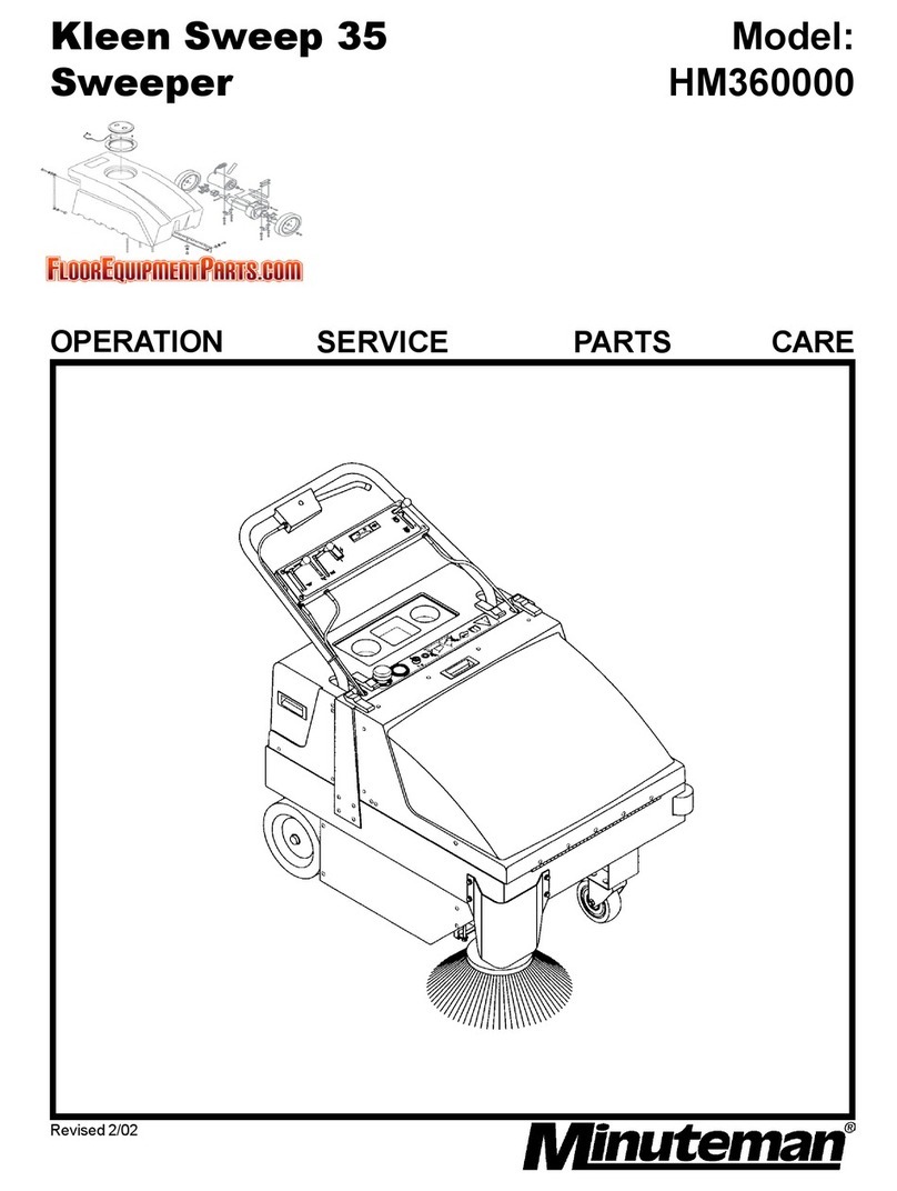
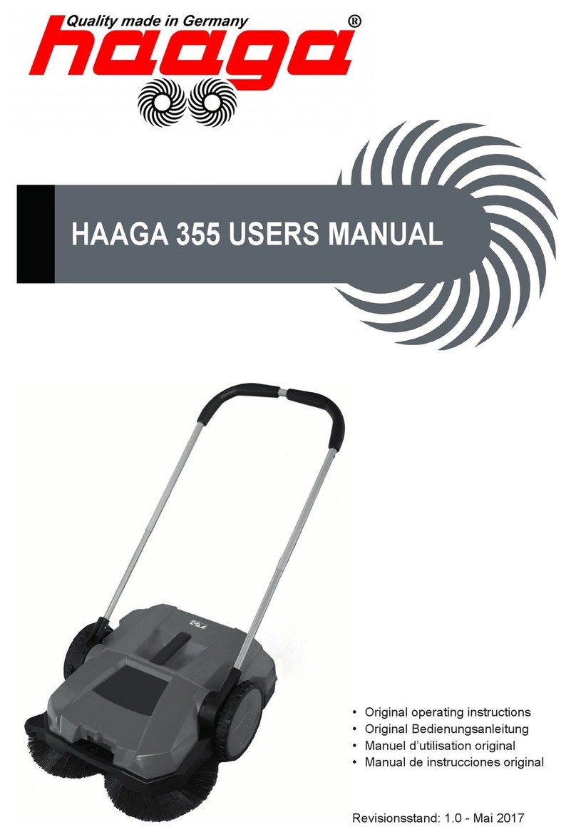
Minuteman Kleen Sweep 35W HM35BQP User manual

Kleen Sweep 35W Model
Sweeper HM35BQP
OPERATION SERVICE PARTS CARE

2
This manual is furnished with each new MINUTEMAN KLEEN SWEEP 35WTM. This provides
the necessary operating and preventive maintenance instructions. Operators must read and
understand this manual before operating or servicing this machine.
This machine was designed to give you excellent performance and efficiency. For best results
and minimal cost, please follow the general guidelines below:
Operate the machine with reasonable care.
Follow the manufacturers suggested maintenance instructions as provided in this booklet.
Use original Minuteman supplied parts.
Technical Specifications
Dimensions and Weight
Length, Total: 54.72" (1.39mm), Width, Total: 31.78" (840mm)
Height Over Handlebar: 40.57" (1030mm)
Weight, Without Batteries: 208lbs (95kg)
Weight, With Batteries: 342lbs (155kg)
Traveling and Sweeping Performance
Speed, Forward: 3mph (4.83km/h)
Sweeping Width, With Side Broom: 34” (850mm)
Sweeping Capacity With Side Broom, Max.: 36.6 sq. ft (3400m2)
Theoretical Max Rate of Climb: 15% grade
Filter System
Filter Area: 1.5 ft2 (0.139 m2)
Number of Filter Elements: 1 piece
Dust Extractor Fan
Speed: 2500rpm
Broom Roller
Length / Dia.: 28.61/9.84" (700 / 250mm)
Wear Limit (approx.): 9" (230mm)
Speed: 510rpm
Sweeping Track Width: 2" (50mm)
Rows of Bristles: 10
Side Broom
Diameter: 12.25" (47mm)
Speed: 94rpm
Dirt Hopper
Capacity: 12.5 Gal (47liters)
Tires
Caster Wheel, Front, Dia.: 4.92" (125mm)
Rear Wheels, Dia.: 5.9" (150mm)
Electric Drive System
DC-Motor Voltage: 12V
Power Rating / Speed: 550W / .75 Hp
Current Dissipation: 57A
Noise Emission
Sound pressure level: 64dB (A)

3

4
TABLE OF CONTENTS
Operation, Illustration, Spare Parts, and Maintenance
IMPORTANT SAFETY INSTRUCTIONS ............................................................. 5
INSPECTION ................................................................................................................6
KLEEN SWEEP 35W – HOW IT WORKS..........................................................................8
ASSEMBLY ..................................................................................................................8
INSTALLING / SERVICING THE BATTERIES.......................................................................8
OPERATION OF THE KLEEN SWEEP 35W .......................................................................9
CONTROLS........................................................................................................ 10
HOW TO USE THE KLEEN SWEEP 35W........................................................................11
SWEEPING WITH THE KLEEN SWEEP 35W....................................................................11
EMPTY DIRT HOPPER.................................................................................................12
TRACTION DRIVE.......................................................................................................12
REPLACE BROOM ROLLER..........................................................................................12
ADJUST SWEEPING TRACK.........................................................................................13
REPLACING THE SIDE BROOM.....................................................................................13
REPLACING THE SIDE BROOM V-BELT.........................................................................14
FILTER SYSTEM – DUST EXTRACTOR ..........................................................................14
MAINTENANCE................................................................................................. 16
EXPLODED VIEWS ........................ FEHLER! TEXTMARKE NICHT DEFINIERT.
TRACTION DRIVE...............................................FEHLER! TEXTMARKE NICHT DEFINIERT.9
TRAVEL DRIVE ..........................................................................................................23
CHASSIS - COVERING ................................................................................................25
STEERING HANDLE ....................................................................................................29
SWEEP ROLLER WITH TRAVEL DRIVE ..........................................................................31
FILTER INSTALLATION.................................................................................................35
LIFTER HOPPER ........................................................................................................37
SIDE BRUSH DRIVE....................................................................................................39
CIRCUIT DIAGRAM........................................................................................... 40
WIRING DIAGRAM............................................................................................ 41
LIMITED WARANTY.......................................................................................... 42
5
IMPORTANT SAFETY INSTRUCTIONS
Operators must read and understand this manual before operating or maintaining this
machine.
Do not operate this machine in flammable or explosive areas.
The following information below may cause a potential hazard to the operator and equipment.
Read this manual carefully and be aware when these conditions can exist. Take necessary
steps to locate all safety devices on the machine and train the personnel operating the
machine. Report any machine damage or faulty operation immediately. Do not use machine
if it is not in proper operating condition.
FOR SAFETY DURING OPERATION:
Keep hands and feet clear of moving parts while machine is in operation.
Make sure all safety devices are in place and operate properly. All covers, doors and latches
must be closed and fastened before use.
During operation, attention should be paid to other persons in the work area and especially if
small children are present.
Electric motors and components can cause an explosion when operated near explosive
materials or vapor. Do not operate this machine near flammable materials such as solvents,
thinners, fuels, grain dust, etc.
Store or park this machine on a level surface only, with parking brake engaged. To prevent
unauthorized use, machine should be stored or parked with the key removed.
This machine is designed for level operation only. Do not operate on ramps or inclines over
15% grade.
This machine is not suitable for picking up hazardous dusts.
Use caution when moving this machine into areas that are below freezing temperatures. Any
water in the tanks or hoses can cause damage to the machine.
FOR SAFETY WHEN SERVICING or MAINTAINING MACHINE:
For safety reasons, the engine hood is equipped with a safety switch. Function of this safety
switch must not be bypassed.
Stop on level surface.
Disconnect the power to the machine when charging batteries or during installation or removal
of brushes.
Avoid moving parts. Do not wear loose jackets, shirts, or sleeves when working on machine.

6
Avoid contact with battery acid. Battery acid can cause burns. When working on or around
batteries, wear protective clothing and safety glasses. Remove metal jewelry. Do not lay tools
or metal objects on top of batteries.
Charging batteries generates explosive gasses. Do not charge batteries when open flames
or sparks are present. Do not smoke. Make sure the charger is turned off before
disconnecting it from the machine.
Charge the batteries in a well-ventilated area with the battery cover removed completely.
Do not clean machine with a pressure washer.
Authorized personnel must perform repairs and maintenance. Use Minuteman supplied
replacement parts.
SAVE THESE INSTRUCTIONS
Proper Use
The Kleen Sweep 35W vacuum sweeper has been designed exclusively for sweeping floor
surfaces, including production facilities, warehouses, parking areas, and pedestrian areas, to
collect dry and moist matter. Whatever sort of use beyond the specified range will be deemed
improper use; the manufacturer cannot be held liable for consequential damage. The term of
proper use also includes compliance with the manufacturer's instructions about operation,
maintenance and repair. The Kleen Sweep 35W may be used, serviced and repaired by
persons only that are familiar with the machine and are aware of possible hazards.
Inspection
Carefully unpack and inspect your Kleen Sweep 35W for shipping damage. Follow unpacking
instructions on shipping pallet. Each unit has been tested and thoroughly inspected before
shipment. Any damage is the responsibility of the delivery carrier who should be notified
immediately.
Electrical
This machine is battery operated and designed to operate on 12 volts DC (2) 6-volt batteries.
Batteries
The recommended batteries are rated 275Ah (Minuteman P/N 956740).
We do not recommend mixing AMP hour capacities. Any alternate battery sets can be used if
they equal physical size and capacity.
Operator Responsibility
Read this manual carefully before operating this machine.
The operator is responsible in taking care of the daily maintenance and check ups of the
machine to keep it in good working condition. The operator must inform the service mechanic
or supervisor when the scheduled maintenance intervals are required as stated in the
MAINTENANCE section of this manual.

7
Special Instructions for Handling Batteries
Never leave batteries in discharged condition for an extended period of time, but re-charge
them as soon as possible. In order to preclude risks to health, eating, smoking and drinking
are forbidden in battery charging stations and rooms. Satisfactory ventilation must exist in the
battery charging area. Batteries must not be connected to or disconnected from the power
supply as long as they are energized. Top up using distilled water only. Never add battery
acid when the cells are in good condition. To avoid leakage currents, make sure that the
batteries are always kept in dry and tidy condition. Protect them against dirtiness, e.g. by
metallic powder. Do not put metallic objects or tools on the batteries. Risk of short circuits and
fuming-off! When handling batteries, wear appropriate protective garments such as protective
gloves and finger-stalls. In particular when checking the acid density, do not use any open
flames (danger of explosion

8
Kleen Sweep 35W – How it Works
The side broom is going to collect dirt out of corners & niches and carries it into the track of the
main broom. Fine dust involved is extracted by a suction fan and held back by a filter. Dust-
free only air will exit the machine.
First Operation
Assembly
To reduce the box volume the handlebar is folded forward and the side broom is packed
unassembled. Assemble these items as follows:
•Unfold the handlebar and secure on both sides with the enclosed hex nuts and
washers. Connect the protective caps.
•Mount the screw to connect the traction drive control bow with the control cable.
•Tilt machine back until resting on the handlebar. Attach side broom with bolt. Bolt
should be torque tightened snugly only to avoid damage to the broom hub.
Installing / Servicing the Batteries
B Open the hood
•Pull the key from the key switch
•Open the hood lock (1) at the front side with a
screw-driver
– Slot horizontal = close
– Slot vertical = open
•Tilt the hood upwards

9
Operation of the Kleen Sweep 35W
1. Traction Drive control bow
2. Control lever for side broom
1. Key Switch
2. Pilot Light, Green
1
2

10
Controls
Traction drive control bow
to connect / disconnect wheel drive
•pull bow on handlebar up = engages traction drive
•return bow = disengages traction drive
(machine will stop = safety mode)
1. Hand wheel for broom roller vertical
adjustment
2. Pedal to set parking brake.
Control lever for side broom
Lowers and lifts the side broom
•Lever horizontal = side broom down
•Lever vertical (up) = side broom up
Control lever for dirt hopper
Unlocks the dirt hopper
•Lever RH = unlocked
•Lever vertical (up) = locked
Rotary knob for suction fan flap
Opens and closes the suction fan flap
•Rotate knob CW = close flap
•Rotate knob CCW = open flap
Note: keep suction fan flap closed when working on wet floors or
with wet matter.

11
Pilot light, GREEN
Turns ON, when Key switch is ON
Key-switch
Connect and disconnect the drive motor and to secure the machine against unauthorized use.
How to Use the Kleen Sweep 35W
Turn motor ON and OFF
•Turn key-switch to “I“ = electric motor runs
•Turn key-switch to “0“ = electric motor stops
Sweeping with the Kleen Sweep 35W
•Start / switch-on
•Open dust extractor fan flap
Note: always keep dust extractor fan flap closed, when sweeping wet areas or wet matter
•Lower side broom
•Actuate traction drive control bow
•Empty dirt hopper as required
Key-switch
Turn ignition ON/OFF, secures machine against unauthorized use
0 = OFF
I = ON
Hand wheel for Main Broom Adjustment
Adjust roller brush load (sweeping track width). Best setting is 2”
(50mm).
•Turn Hand wheel CW = Reduced track width (low brush load)
•Turn Hand wheel CCW = Extended track width (high brush
load)

12
Empty Dirt hopper
Traction Drive
The traction drive system uses a friction wheel (1) and a V-belt (2) driving the wheel axle.
When actuating the traction drive control lever, the friction wheel arm (3) with its friction wheel
(1) is pressed against the drive shaft (7), thus allowing power transmission. Note: dust
extractor fan and side broom will rotate as soon as motor is running. Keep hands and fingers
away from any moving parts to avoid injury.
Replace Broom Roller
The broom roller bears 10 rows of bristles and consists of 4 halves. A new broom is 9.8" dia.
(250mm). The broom roller should be replaced when reaching a dia. of 9" (230 approx. mm) to
function properly.
To remove the broom roller:
•Tilt the Kleen Sweep 35W back on the handlebar, as shown. Remove 4 ea. cylinder
Hexagon screws, rotate roller through 180, and remove cylinder Hexagon screws from
1 Dirt hopper control lever 2 Latch
3 Bar for dirt hopper wheels 4 Dirt hopper
•Depress lever (1) to the right to unlock
•Hold dirt hopper by its handle (3) and
pull to the rear, empty hopper
•Slide dirt hopper into opening, exert
pressure against latch (2) until click is
audible, to ensure the dirt hopper is
installed in place.
1. Friction wheel
2. V-belt
3. Friction wheel arm
4. Cocking roller for broom roller drive
5. V-belt for broom roller drive
6. Control cable for friction wheel arm
7. Drive shaft for traction drive, broom roller
and side broom drive assy’s.

13
the other half. Pull drive pin out of broom shaft. For installation, reverse the above
sequence of operations.
Adjust Sweeping Track
In case of broom roller wear and after replacing the roller broom, adjust sweeping pattern as
follows:
•Start the machine and rotate broom roller for a short period of time (static)
•Lift front end of machine and pull back.
•If adjusted properly, a parallel line of sweep is visible on the ground (sweeping track).
This sweeping track width is adjusted to approx. 2" (50 mm) by rotating the hand wheel
CW or CCW. Sealing strips (1 to 4) have to be inspected for wear in regular intervals
and replaced as required. Sealing strips slightly should touch the ground.
Replacing the Side Broom
•Tilt the Kleen Sweep 35W back on its handlebar (also refer to previous section, "replace
broom roller")
•Remove attaching bolt (1) underneath side broom
•Pull-off side broom
•Plug-on new side broom and secure; torque attaching bolt light tight only, to avoid
damage to the broom hub.
1. Sealing Strip, Forward
2. Sealing Strip, Right Hand
3. Sealing Strip, Rear
4. Sealing Strip, Left Hand
5. Broom Roller

14
Replacing the Side Broom V-Belt
•Tilt the Kleen Sweep 35W back on its handlebar (refer to section, “Replace Broom
Roller”)
•Remove hood (3 ea. Screws)
•Lift side broom and uncock round belt
•Remove round belt and assemble new one.
•NOTE: Refer to direction arrow.
Filter System – Dust Extractor
fine dust in the broom housing is suctioned through a filter module by the dust extractor fan.
The filter module (1) is located in the rear part of the machine and is removed as follows:
1 side broom attaching bolt
2 round belt for side broom drive
3 V-belt for broom roller drive
4 Round belt
5 Pulley

15
•Disconnect Power
•Remove dirt hopper
•Unhook straps (2) at top end and remove filter module (1)
•Carefully shake filter clean or clean with vacuum cleaner (do not damage filter element)
•Re-assemble filter module in true position (arrow towards machine) and re-attach straps
•Install dirt hopper
1. Filter Module
2. Straps

16
Maintenance
Compliance with our recommended maintenance and service schedule will guarantee a
dependable machine all the time. It is better and cheaper to take precautions instead of facing
costly repair work. If your in-house facilities are unable to perform the work per maintenance
schedule, your authorized distributor will be glad to conclude a maintenance agreement with
you. For all inquiries or parts orders, always specify chassis and motor numbers as printed on
the data plate. The data plate is located on the left side under the hood of the handlebar. When
performing cleaning or service work or replacing parts, stop the motor, pull ignition key and
disconnect the power. Use adequate tooling for maintenance, servicing and adjustment jobs
only. As far as safety is concerned, spare parts will at least be of the same quality as genuine
parts. When working on the electrical system, disconnect battery plug.
Per Service Hours
Daily 50 100 200
Empty dirt hopper, clean
the guide edges inside the
chassis
Check broom roller and
side broom for wear and
foreign matter (e.g. Tape,
Wire), replace as required
Charge Batteries Check sweeping track
width, adjust as required
Check all sealing strips for
appearance, replace as
required. Strip tips should
slightly tough the floor;
adjust as required
Check drive belts for wheel,
extractor fan, broom roller
and side broom for
appearance and wear,
adjust tension or replace as
required
Check traction drive control
cable, adjust as required
Check dust extractor and
filter system for good seal,
replace as required
Check dust extractor fan
and flap for function
Check dirt hopper lock
Clean Motor, Check carbon
brushes for ease of
movement and wear, clean
as required

17
Exploded views

18

19
Traction Drive
Bild Best.-Nr. Stck. Teilbezeichnung Description
Item PN Qty.
Rép. Réf. No. Oté.
1 10-450 5 6kt-Schraube Hex. bolt
2 73-094 8 Sperrkantscheibe Detent washer
3 05-309 3 6kt-Schraube Hex. bolt
4 04-290 1 Scheibe Washer
5 53-168 1 Riemenscheibe Belt pulley
6 53-173 1 Bolzen Bolt
7 13-512 2 Scheibe Washer
8 70-541 1 Kugellager Ball bearing
9 05-150 1 6kt-Mutter Hex. nut
10 15-518 3 Paßscheibe Adjusting shim
11 02-223 1 Sicherungsring Retaining ring
12 04-652 2 Scheibe Washer
13 74-590 1 Riemenscheibe Belt pulley
14 71-224 1 Riemen Conti-V Belt conti-V
15 13-375 1 Kontrolleuchte, grün Pilot lamp, green
16 101-426 1 Glühlampe Bulb
17 107-492 1 Verschlussstopfen Plug
18 02-171 1 Schlüsselschalter Key switch
19 05-308 6 6kt-Schraube Hex. bolt
20 66-168 1 Lüfterrad Fan wheel
21 90-355 1 Sicherung Fuse
22 74-468 1 Magnetschalter Ignition switch
23 90-351 1 Sicherungshalter Fuse holder
24 15-283 1 Klemmblock Clamping block
25 52-591 2 Schutzkappe Protective cap
26 05-134 3 6kt-Mutter Hex. nut
27 32-192 1 Halterahmen Hold frame
28 13-383 2 6kt-Mutter Hex. nut
29 50-956 1 Sicherungsgehäuse Fuse box
30 90-612 1 Stecksicherung Fuse link
31 12-632 2 Sicherungsring Retaining ring
32 70-636 2 Kugellager Ball bearing
33 02-234 1 Sicherungsring Retaining ring
34 05-426 1 Paßfeder Adjusting spring

20
Table of contents
Other Minuteman Blower manuals

Minuteman
Minuteman Kleen Sweep 40 User manual

Minuteman
Minuteman AD100 User manual

Minuteman
Minuteman HC8880K HC8880KHC9408H Guide

Minuteman
Minuteman C43000-002H User manual

Minuteman
Minuteman KLEEN SWEEP 45 User manual

Minuteman
Minuteman Kleen Sweep 25W User manual

Minuteman
Minuteman HT9605H Guide

Minuteman
Minuteman Kleen Sweep 27 C89000-00 Guide

Minuteman
Minuteman PowerBoss 36 Guide

Minuteman
Minuteman PowerBoss 3800 Guide