Minuteman TRS17 User manual

Parts and Instruction Manual
TRS17 Total Recovery System

Parts and Instruction Manual - TRS17 Total Recovery System
Model TRS17
Technical Specifi cations
Model TRS17-115
^ŽůƵƟŽŶdĂŶŬ 17 gallon
ZĞĐŽǀĞƌLJdĂŶŬ 15 gallon
sĂĐƵƵŵDŽƚŽƌ Single 3-stage
WƵŵƉ 600 psi/.85 GPM – 480 psi nozzle
tĂƚĞƌ>ŝŌ 120”
dĂŶŬŽŶƐƚƌƵĐƟŽŶ Polyethylene
ĂƐĞƉůĂƚĞ ¼” aluminum
ZĞĂƌtŚĞĞůƐ 10” non-marking
ĂƐƚĞƌƐ 4” locking
WŽǁĞƌŽƌĚ ϱϬŌ
ŝŵĞŶƐŝŽŶƐ 39”H x 37”L x 22”W
tĞŝŐŚƚ 108 lbs.
ůĞĐƚƌŝĐĂůƌĂǁ 14.5 amps
sĂĐƵƵŵ^ŽůƵƟŽŶ,ŽƐĞ 25’
tĂŶĚ Swivel wand with squeegee/brush head
WƌĞƐƐƵƌĞ'ƵŶ Included
&ŝdžƚƵƌĞƌLJŝŶŐ,ŽƐĞ 25’ x 1.5” Diameter
tĂƌƌĂŶƚLJ ϯLJĞĂƌƉĂƌƚƐϮLJĞĂƌƐůĂďŽƌůŝĨĞƟŵĞŽŶďŽĚLJ
SPECIFICATIONS:

Parts and Instruction Manual - TRS17 Total Recovery System
Table of Contents
INSPECTION ......................................................................................................................................... 4
SAFETY INSTRUCTIONS ..................................................................................................................... 5
GFCI ...................................................................................................................................................... 7
GROUNDING ........................................................................................................................................ 9
MAINTENANCE .................................................................................................................................. 10
MACHINE OVERVIEW ........................................................................................................................ 12
OPERATION ........................................................................................................................................ 14
UPPER ASSEMBLY ............................................................................................................................ 18
UPPER ASSEMBLY BOM ................................................................................................................. 19
UPPER ASSEMBLY BOM (page 2) .................................................................................................... 20
LOWER ASSEMBLY ........................................................................................................................... 21
LOWER ASSEMBLY BOM (page 1) ...................................................................................................22
LOWER ASSEMBLY BOM (page 2) ...................................................................................................23
LOWER ASSEMBLY BOM (page 3) ...................................................................................................24
Warranty ............................................................................................................................................. 26

Page 4
Parts and Instruction Manual - TRS17 Total Recovery System
INSPECTION
UNPACKING YOUR NEW 534505"-3&$07&3:45:45&.:
When your package is delivered, check the carton carefully for signs of rough handling. If your 534
is damaged, notify the carrier immediately and request an inspection. Be sure to keep the carton,
packing inserts, packing lists and carrier’s receipt until the inspector has verified your claim.
MINUTEMAN’s liability ceases when the carrier picks up the shipment. However, our customer service
staff will be happy to furnish any information needed in connection with the claim and will attempt to
expedite a resolution.
PLEASE READ BEFORE OPERATING YOUR NEW BURNISHER:
Read the manual carefully and completely before attempting to operate the unit. This manual has
important information for the use and safe operation of the machine. Keep this manual handy at all
times.
This equipment has been engineered and manufactured to provide excellent performance and service. To
ensure that your equipment will continue to perform as intended:
tMaintain equipment regularly- following the suggested maintenance schedule provided.
tUse only original MINUTEMAN parts when servicing.
tOperate equipment with care.
If additional information is needed, please contact:
MINUTEMAN INTERNATIONAL 630- 627-6900
"ll information and specifications printed in the manual are current at the time of printing;
however because of MINUTEMAN’s policy of continual product development, we reserve the right
to make changes at any time without notice.

Page 5
Parts and Instruction Manual - TRS17 Total Recovery System
SAFETY INSTRUCTIONS
FOL
LOWING WARNINGS AND INSTRUCTIONS WILL VOID THE
WA R R A N T Y.
WA R N I N G !
tThe machine was designed for use on hard surfaces, applications as per instructions and
recommendations written in this manual. Any deviation from its proper use or purpose and the
consequential damage that may occur is the sole responsibility of the end user.
tDisconnect the power cord from the outlet before servicing. Do not leave machine connected to an
electrical outlet when unattended.
tDo not immerse or use this machine in standing water. Such use may cause electric shock.
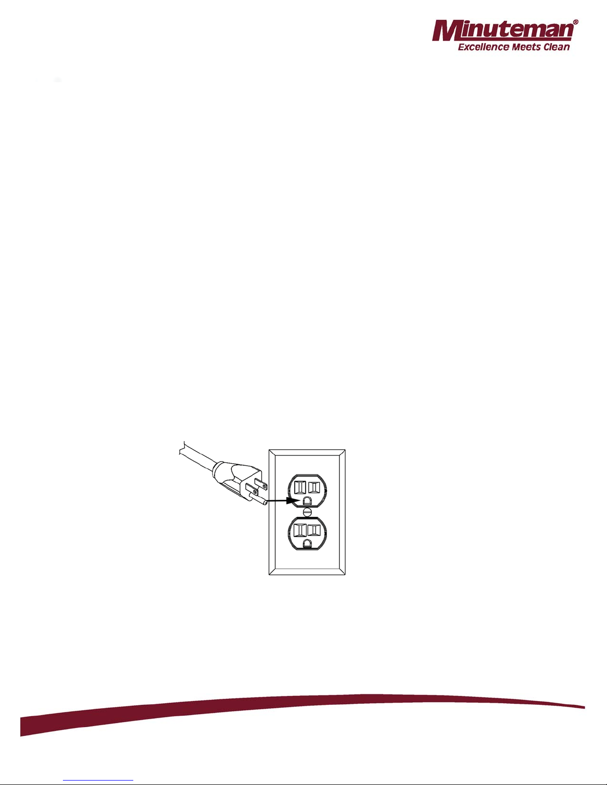
tWhen using an extension cord, use only a 3-prong conductor grounding cord-12 gauge wire or
heavier.
tTo avoid electric shock, do not expose the unit to rain or snow. Store it indoors in a heated location
only.
tDo not use the machine for dry vacuuming.
tUse defoamer at all times to prevent damage to the vacuum motor.
tDo not use water in excess of 130°F (54°C) in the solution tank
tTo prevent seal damage and chemical build-up to the pump system, run clean water through the
solution lines after each day’s use.
tUse only commercially available carpet cleaning solutions and defoamer intended for use with
machines of this type. Do not use dyes, bleaches, ammonia, or other additives.
tThe use of powdered cleaning solution, if not diluted properly, may result in damage to the pump.
Powdered chemical is not recommended. If powdered chemicals are used, premix in a separate
container before placing in the solution tank.
tAlways read and understand your chemical’s MSDS (Material Safety Data Sheet) before use.
tThis equipment is not designed to handle or use combustible/volatile substances such as gasoline or
kerosene, in, on, or near the machine. The use of such materials will cause extreme hazardous
condition.

Page 6
Parts and Instruction Manual - TRS17 Total Recovery System
tDo not expose machine to freezing temperatures.
tAll repairs must be done by an authorized MINUTEMAN repair station.
tDo not use replacement parts other than original MINUTEMAN parts.
tDo not allow your spray stream to remain in one fixed location as surface damage may occur.
tCheck that all spray nozzles are securely fastened. Loose nozzles could be ejected from equipment at
high speeds.
tPrevent burns by wearing gloves or using a barrier to remove hot quick disconnects.
tThis is not a toy. Keep away from children.
tDo not pull by the power or use power cord as a handle. Always unplug by grabbing the plug and
pulling, do not unplug by pulling the power cord.
tInspect cord for damage. Do not use damaged cords. Connect only to properly grounded outlets.
tKeep hair, fingers, loose clothing, and body parts away from moving parts and openings.
tTurn off all controls before disconnecting machine
tUse caution with ejected liquid or chemicals. High pressures and temperatures could be hazardous to
nearby people or surroundings.
ELECTRICAL - 115 Volt
Model: TRS-17
This machine is designed to operate on a standard 15 amp, 120 volt, 60 Hz, AC circuit. Voltages below
105 volt AC or above 125 volts AC could cause serious damage to the motor.

Page 7
Parts and Instruction Manual - TRS17 Total Recovery System
GFCI
GFCI:
WARNING: Do not tamper with or disable the GFCI function.
WARNING: Do not remove the grounding pin from your power cord. Doing so will
prevent the GFCI from performing properly and can allow dangerous operating
conditions to go undetected. Replace power cords without grounding pins
immediately.
GFCI FUNCTION:
For your safety, your TRS-17 is equipped with a built in GFCI (Ground Fault Circuit Interrupter).
The GFCI function is automatic and, under normal operating conditions, the GFCI function will not
be activated.
A GFCI works by monitoring the amount of current that is flowing from hot to neutral. If the GFCI
senses an imbalance in that flow, such as a ground leak, it will disable (interrupt) the electrical system
to eliminate dangerous operating conditions. When the electrical system has been disabled, you will
not be able to run the TRS-17, at all, until you reset the GFCI.
Before resetting, It is best practice to investigate the cause of a GFCI tripping the circuit.
Possible causes and solutions are:
tYour equipment has become wet and moisture has come in contact with the electrical system. Take
unit to an authorized repair location for servicing.
tYour machine is submerged in liquid. If it is safe to do so, remove the equipment and take unit to
an authorized repair location for servicing.
tThere is damage to the power cord. Replace the power cord immediately with the correct spec cord.
tThe wall plug or cord plug may be wet or in contact with water. Using thick rubber gloves, unplug
the cord from the wall.
tA leak in your machine’s plumbing may be wetting the internal electrical components. Take the
unit to an authorized repair location for servicing.
tThere is a loose or faulty electrical connection some- where in your equipment. Take the unit to an
authorized repair location for servicing.

Page 8
Parts and Instruction Manual - TRS17 Total Recovery System
To restore function to your equipment when the GFCI has tripped the circuit, press the button on the
GFCI marked “RESET”.
If a GFCI continues to trip after resetting, it indicates an unsafe operating condition is present and it is
best to take it to an authorized repair location for servicing. Contact MINUTEMAN for assistance in
locating an authorized repair location.
GFCI MAINTENANCE:
Although the GFCI function works on its own, it is necessary to test for proper function of your GFCI
periodically.
To do this:
1. Plug your equipment to an appropriate wall plug
2. Press the “TEST” button on the GFCI panel
3. Turn on the switches for “PUMP” and “MOTOR” (located on the switch panel on the handle).
If your motors turn on, then the GFCI is NOT working properly- do not use the equipment until this
function has been repaired. Take the machine to an authorized repair location.
If neither motor powers on after pressing the “TEST” button then the GFCI is working properly.
Press the “RESET” button on the GFCI and the TRS-17 will be fully functional again.

Page 9
Parts and Instruction Manual - TRS17 Total Recovery System
GROUNDING
GROUNDING INSTRUCTIONS:
This piece of equipment must be grounded. Should an electrical malfunction occur, grounding
provides a path of least resistance for electrical current- reducing the risk of electric shock. This piece
of equipment is furnished with a cord that has a grounding conductor and grounding plug. The
grounded plug must only be plugged into an appropriate outlet that is properly installed and grounded
in accordance with all local codes and ordinances.
WA R N I N G :
Connecting the equipment to an improperly grounded outlet can result in an increased risk of electric
shock. A qualified electrician should be consulted if you are unsure that the outlet is properly grounded.
Do not modify the plug provided with the equipment. If it will not fit the outlet, have a proper outlet
installed by a qualified electrician.
This appliance is designed for use on a 120-volt circuit. The grounding plug provided looks like the plug
illustrated in Figure 1. Replace the power cord if the grounding pin is damaged or broken.
Extension cords connected to this machine should be 12 gauge, three-wire cords with three-prong
plugs and outlets. DO NOT use extension cords more than 25 feet (7.6 m) long
Figure 1

Page 10
Parts and Instruction Manual - TRS17 Total Recovery System
MAINTENANCE
MAINTENANCE:
This TRS-17 has been engineered and built to require minimum maintenance. But like any machine, it
does require some care to keep it in optimum working condition. Careful attention to these maintenance
instructions will give you maximum operating performance and life expectancy of the machine.
CAUTION: Disconnect the power cord from the outlet before doing any clean up or maintenance
on the machine
1. Keep the machine clean. Do not allow dust to accumulate on external surfaces or near any moving
parts.
2. After every job, wipe down the surface of the machine with a clean damp cloth.
3. Inspect cord for damage. Do not use machine with a damaged cord.
PERIODIC MAINTENANCE
tUse only chemicals safe for extractors
tAdhere to the appropriate mix ratios for all chemicals
tDo not add chemical to the solution tank- use the chemical feed system or pre-spray
tFor optimal performance, it is suggested that the operator flush the system after every job or at the
end of the day.
tPump seals and valves may need to be replaced at the 1000 hour mark if a loss in pressure is noted
tThe pressure regulator may require servicing should a pressure drop be noted
Daily:
tFlush chemical lines with water by placing clean water in the solution tank and using the pump to
spray.
tCheck and clean vacuum filter
Weekly:
xCheck for obstructions in vacuum pathways
xQuarterly:
xCheck pump, plumbing and fittings for leaks
xCheck power cords and hoses for tears
xCheck and clean solution filter

Page 11
Parts and Instruction Manual - TRS17 Total Recovery System
CORD STORAGE:
While not in use, storage can be accomplished by winding cord around handle assy. Cord should be
completely unwound during operation.
CORD SAFETY
xDo not leave appliance when plugged in. Unplug from outlet when not in use and before
servicing
xDo not use with damaged cord or plug. If appliance is not working as it should, has been dropped,
damaged, left outdoors, or dropped into water, return to service center for inspection and repair.
xDo not pull or carry by cord, use cord as handle, close a door on cord, or pull cord around sharp
edges or corners. Do not run this TRS-17 over cord. Keep cord away from heated surfaces.
xDo not unplug by pulling cord. To unplug, grasp the plug, not the cord.
xDo not handle plug or appliance with wet hands.
xThis equipment should be stored indoors and not exposed to rain.

Page 12
Parts and Instruction Manual - TRS17 Total Recovery System
MACHINE OVERVIEW
1. Handle- Used to maneuver and position the TRS-17. Contains switch box (For switchbox, see #18)
2. Recovery tank lid- Allows access to recovery tank and creates a seal to ensure suction
3. Solution tank lid- Allows access to the solution tank and prevents external contamination of solution
tank
4. Accessory racks for hoses, cords, tools etc.- One large rack and one small rack on each side of the
machine. 4 total.
5. Wand storage bracket and velcro strap- Allows the operator to secure a wand attachment to the machine
for ease of transport
6. Non-marking front 4” locking casters and rear 10” wheels
7. Recovery/vacuum hose inlet barb- connect your recovery vacuum hose to this barb
8. Feed hose line for chemical with threaded bottle cap- secures the feed hose line to the chemical bottle
9. Bottle holder for chemical feed system- Holds up to a one gallon chemical bottle
10. GFCI breaker- Interrupts and disables the electrical system if a ground leak is detected.
11. Chemical dispensing valve- Select between “SOAP” and “RINSE” by turning to left or right as marked
12. Male twist lock pigtail- Connects to 50 ft. cord
13. Exhaust port hose barb- Used to connect to hose with blower attachment.
14. Pressure regulator- Decrease pressure by turning counter-clockwise or increase pressure by turning
clockwise
15. Priming/pressure relief valve- Prime system in the event of air lock. Relieves pressure in the event of
pressure lock
16. Solution line Q.D.- Pressurized connection for solution line
17. Recovery tank dump valve- Pull up to open
18. Switch box- one switch marked “PUMP” and one switch marked “VACUUM”. Switches light up when
powered on.

Page 13
Parts and Instruction Manual - TRS17 Total Recovery System
3 2
1
4
8
65
9
10
11
12
13 14
15
16
17
18
7

Page 14
Parts and Instruction Manual - TRS17 Total Recovery System
OPERATION
Assembling the accessory racks:
5IF534JTTIJQQFEXJUIUIFBDDFTTPSZSBDLTBOEIBSE XBSFJOUIFTPMVUJPOUBOL8IFOZPVSFDFJWF
ZPVS534JUJTOFDFTTBSZUPTFDVSFUIFSBDLTUPUIFCPEZ5IF POMZUPPMSFRVJSFEUPDPNQMFUFUIF
BTTFNCMZJTB1IJMMJQT IFBETDSFXESJWFS
5IF534DPNFTFRVJQQFEXJUIUISFBEFEJOTFSUT QSFJOTUBMMFEJOUIFCPEZ5IFUXPMBSHFSSBDLTBSF
JOTUBMMFEUPXBSEUIFGSPOUPGUIFNBDIJOFPOFQFSTJEFBOE UIFUXPTNBMMFSSBDLTBSFJOTUBMMFEUPXBSEUIF
SFBSBMTP POFQFSTJEF
Opening the machine:
5IJTVOJUDBOCFPQFOFECZTJNQMZSFNPWJOHUXPCPMUT MPDBUFEPOUIFCBDLPGUIFNBDIJOF5IFVOJUXJMM
PQFO GPSXBSECZMJGUJOHVQPOUIFIBOEMF*GZPVOFFEUPPQFOUIFVOJUGVSUIFSZPVNBZSFMFBTFUIF
WBDVVNIPTFHPJOHGSPNUIFCBTFPGUIFWBDVVNQMBUFUPUIFCPUUPNPGUIF SFDPWFSZUBOLCZMPPTFOJOH
UIFIPTFDMBNQ
#0-54

Page 15
Parts and Instruction Manual - TRS17 Total Recovery System
Installing metering tips for the Chemical feed system:
Remove the semi-clear hose from the bottle cap (#8 on page 7). Select the appropriate metering tip for
the dilution required and push it into the tube on the bottle cap.
Metering tip color guide:
Tan 1.25oz/Gal
Turquoise 2.00oz/Gal
Pink 3.00oz/Gal
Brown 4.00oz/Gal
White 5.00oz/Gal
Chemical feed system and hard surface cleaning:
The chemical feed system is designed to deliver accurate chemical dilution for touchless surface
cleaning.
To clean hard surfaces:
1. Fill the solution tank of your TRS-17 with sufficient water for the task at hand.
2. Connect solution hose and accessory pressure gun
3. Select the appropriate tip and install on the cap of the chemical feed (#8 on page 7).
4. Place a bottle into bottle holder (#9 on page 7).
5. Take the feed tube attached to the cap (#8 on page 7) and place it inside the bottle.
6. Take the cap from #8 on page 7 and thread it onto the bottle of chemical to secure it in place.
7. Turn the chemical dispensing valve (#11 on page 7) to the left toward the word “SOAP”.
8. Chemical will draw in the “HIGH” or “LOW” pressure settings of your pressure gun. To activate
the “LOW” pressure setting, pop the collar of the gun out.
9. In either “HIGH” or “LOW” pressure, apply chemical to the walls and fixtures starting from the
lowest point to the highest.

Page 16
Parts and Instruction Manual - TRS17 Total Recovery System
10. Spray the floor as you make your way out of the room
11. Allow the chemical to dwell according to the chemical manufacturers recommendations
12. You may use the brush on your squeegee/brush wand to agitate particularly soiled areas
13. When you are ready to rinse away the chemical, simply turn the chemical dispensing valve (#11 on
page 7) to the word “RINSE”
14. Set your pressure gun to the desired pressure by pulling the collar in or out. Rinse surfaces starting
from the top down
15. See “Recovering liquid” for final steps
Recovering liquid from hard surfaces:
The TRS-17 is equipped with two dedicated tools for liquid recovery: The squeegee/brush wand and the
Gulper tool.
1. Connect recovery vacuum hose to the recovery inlet barb (#7 on page 7).
2. Place the vacuum switch (see #18 on page 7) into the “ON” position.
3. Using either the squeegee/brush wand or the Gulper tool, to extract the liquid from the surface. (see
page 8).
4. Monitor the levels in the recovery tank and empty as necessary. Use defoamer to ensure your vacuum
motor does not take in foam/fluid.
Using the blower feature:
To use, this feature connect the Blower hose (#5 on page 8) to #13 on page 7 and turn on the vacuum
motor.
Convenient for:
tBlowing fluid off countertops and walls onto the floor
tDrying faucets and other fixtures
tBlowing off dust
NOTE: Do not leave the blower hose on during normal extraction as it will reduce suction.

Page 17
Parts and Instruction Manual - TRS17 Total Recovery System
NOTES

Page 18
Parts and Instruction Manual - TRS17 Total Recovery System
UPPER ASSEMBLY
756
833(5

Page 19
Parts and Instruction Manual - TRS17 Total Recovery System
UPPER ASSEMBLY BOM
BILL OF MATERIAL
ITEM PART # QTY DESCRIPTION
110989-2A 1 BALL FLOAT
2 A00060 1 BARB, 3/8" X 1/4"MPT, BRASS
3 A00052 4 90 DEGREE ELBOW, .25MP X .25FP
4 A00124 2 LOCKNUT, .25NPT, BRASS
5 A00139 1 BARB, .25 X .25MP, BRASS
6 A13881 1 CHECK VALVE
7 A90004 1 BARB, .5 X .25MP, BRASS
8 B010314 1 WIRE HARNESS
9 B02211-1 2 ROCKER SWITCH
10 C00234 1 WASHER, FENDER, 1/4", SS
11 C00238 7 1/4" ID SEALING WASHER
12 C00288 4 SCREW, 1/4-20 X 1.5", FLAT HEAD
13 C00288-1 4 SCREW, 1/4-20 X 2.25, FLAT HEAD
14 C00295-1 2 #10 X 3/4" SHEET METAL SCREW, SS
15 C00313 4 1/4-20 X 3/4" HEX BOLT
16 C00316 1 SCREW, 1/4-20 X 3/4, PH, SS
17 C02251 1 JAM NUT, 1/4-20, SS
18 C02282 4 HEX BOLT, 1/4-20 X 1 1/2"
19 C11144 2 SCREW, 1/4-20 X 2" SS
20 C11167 2 1/4-20 X 3/4" SCREW, SS
21 C11244 3 WASHER, 9/16" ID X 1.5" OD
22 C11540 2 WASHER, 5/16"
23 C12021 1 WASHER, FLAT, 9/16 ID, SS
24 C12039 4 FENDER WASHER, 1/4" ID, 1" OD
25 C12110 2 HEX BOLT, 3/8-16 X 1 3/4
26 C14017 8 SCREW, 10-32 X 1/2", TRUSS

Page 20
Parts and Instruction Manual - TRS17 Total Recovery System
UPPER ASSEMBLY BOM (page 2)
BILL OF MATERIAL
ITEM PART # QTY DESCRIPTION
27 D00373 2 FILTER, INLET
28 D010284 1 SWITCHPLATE
29 D03421 1 COVER, SWITCHPLATE, 2 SWITCH
30 D13683 1 BOTTLE HOLDER, CHEMICAL
31 D13697 2 RACK, HOSE
32 D13698 2 RACK, POWERCORD/GUN
33 E010453 1 GASKET, SWITCH BRACKET
34 E03433 1 GASKET, SWITCH BRACKET
35 E11128 2 DRAIN VALVE GASKET
36 E11836 1 GASKET, RECOVERY TANK, LID
37 F11785-1-MM 1 LID, RECOVERY TANK
38 F11786-1-MM 1 HANDLE
39 F11787-1-MM 1 SOLUTION TANK
40 F11788-1-MM 1 RECOVERY TANK
41 F11791-1-MM 1 LID, SOLUTION TANK
42 H13699 1 DECAL, MINUTEMAN, WHITE
43 K00665-1 1 1-1/2" HOSE ADAPTER
44 K00666 1 1-1/2" 90 DEGREE ELBOW
45 K00672 1 PVC PIPE, 1.5" SCH40, 1.3125'
46 K00672-1 1 PVC PIPE, 1 1/2" X 2.25", SCH40
47 K00711 1 DRAIN VALVE
48 K00741 1 ADAPTER, MALE, 1 1/2", SCH40
49 K11185 1 90 DEGREE ELBOW, SCH40, MPT, SF
50 K11965 1 RETURN BEND, 1 1/2"
51 S11179 1 NON-SKID TAPE
52 S13706-A 1 STRAP, WAND, VELCRO
Table of contents