MinXray HF100H User manual

MinXray HF100H
High Frequency Portable Medical X-ray unit
Installation and Operating Instructions
Version 2.0
CAUTION;
Federal law restricts this device to sale and use
by or on the order of a licensed physician.
MinXray, Inc.
3611 Commercial Avenue
Northbrook, Illinois 60062-1822
U.S.A.
Tel: 1-847-564-0323
Toll Free Tel: 1-800-221-2245 (U.S. and Canada)
Fax: 1-847-564-9040
www.minxray.com

TABLE OF CONTENTS
Introduction 1
Certifications 2
Components 3
Main Parts 4
Control Panel 5
Warning Statements, Figures and Symbols 6
Installation Instructions
Unpacking 7
Assembly Instructions 7
Pre-Operational Required Testing 8
Installation Check List 11
Operation Instructions
Operation 12
Safety Precautions 14
Maintenance 14
Specifications 16
Dimensions 17
Schematic Diagram 18
X-ray Tube Data 19

INTRODUCTION
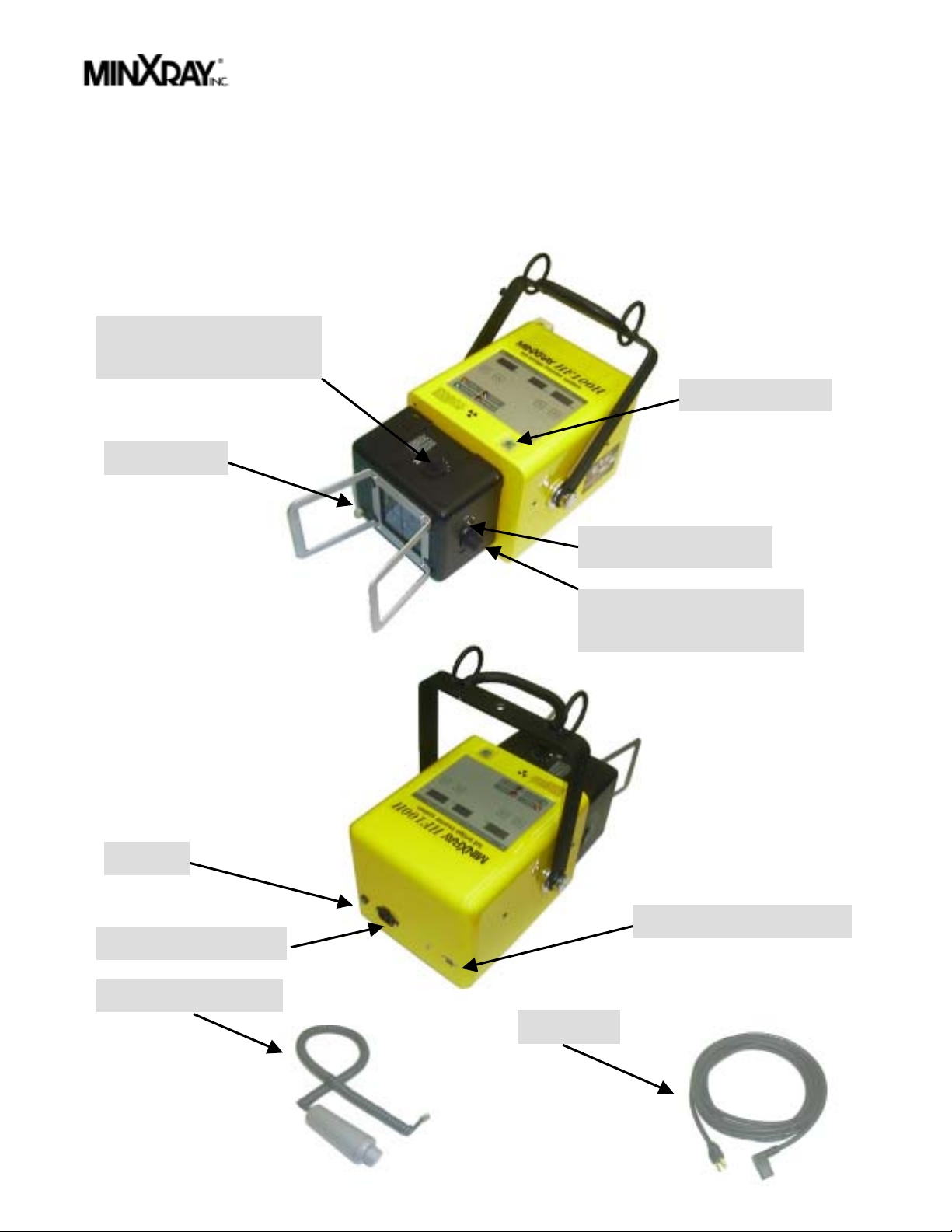
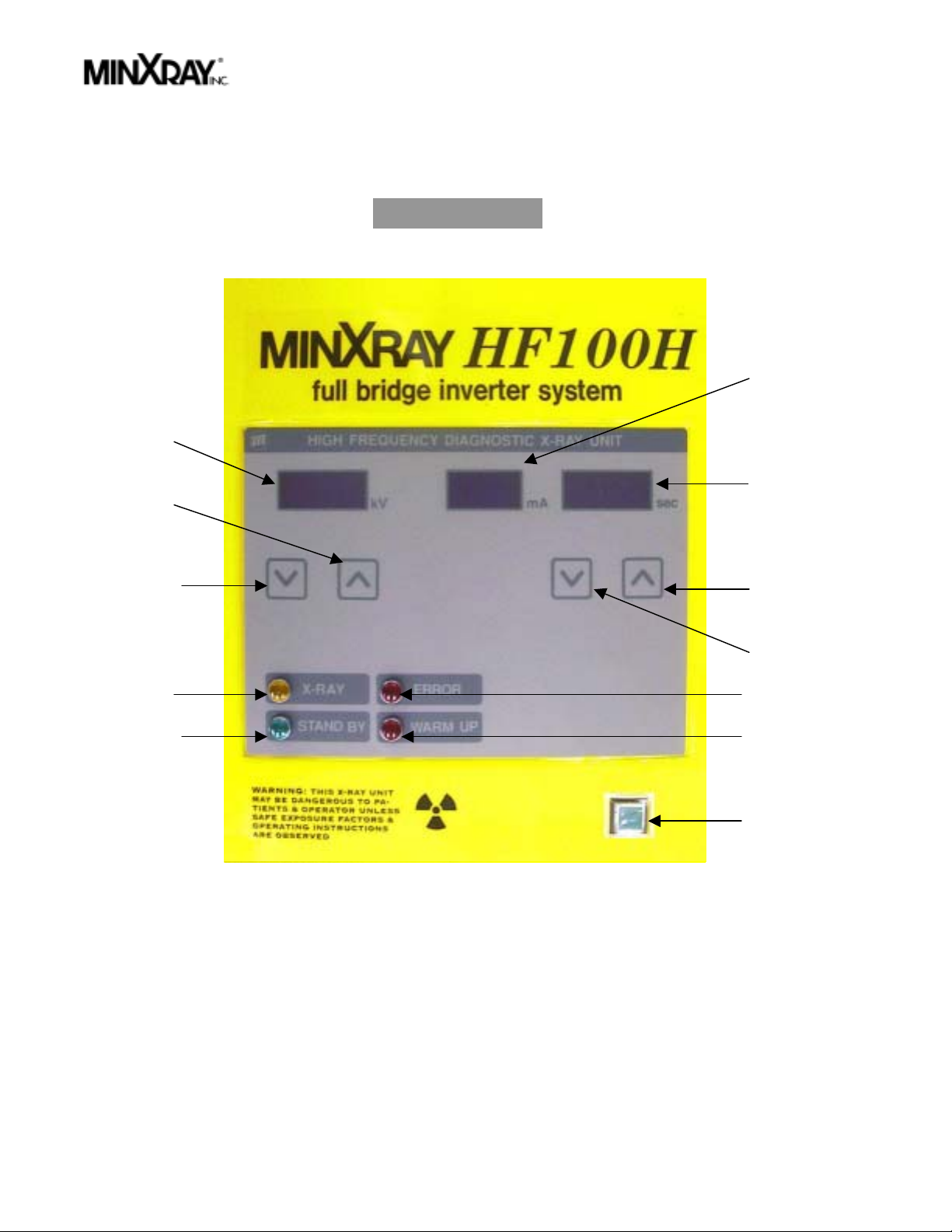
The MinXray HF100H is a mono-block type high frequency portable x-ray unit designed for general
purpose medical radiography. The HF100H can be used with conventional x-ray film or with digital
imaging media. It consists of an x-ray tubehead/control attached to which is a continuously
adjustable light beam collimator. A trunnion enables the HF100H to be attached to a suitable stand,
such as the MinXray XGS series of portable mobile stands. The HF100H is supplied with a
detachable AC power cord, and a detachable exposure cord with a 2-stage exposure switch.
CARELESS OR IMPROPER USE OF X-RAY EQUIPMENT CAN BE EXTREMELY HAZARDOUS. It
is imperative that this equipment be operated and serviced only by trained personnel familiar with
the safety precautions required to prevent excessive exposure to primary X-ray radiation, the
dangers of exposure to X-ray radiation, and the proper use of the equipment discussed in this
manual.
All personnel authorized to operate or service this equipment should be fully acquainted with the
established maximum permissible doses, safety recommendations, and procedures derived from the
following sources:
A. National Council on Radiation Protection Report No.33 (Medical X-Ray and Gamma Ray
Protection for Energies up to 10 MEV - Equipment Design and Use); from NRCP
Publications; P.O. Box 30175, Washington, D.C. 20014.
B. National Bureau of Standards Handbook No.76 (Medical X-Ray Protection up to Three
Million Volts); from the Superintendent of Documents, Government Printing Office,
Washington, D.C. 20401.
C. All documents relating to the Performance Standard for Diagnostic X-Ray Systems, 21
CFR Subchapter J, Part 1020; obtainable from FDA Center for Devices and Radiological
Health, Department of HHS, 2098 Gaither Road, Rockville, MD 20850.
D. State and local regulations governing radiation protection and the use of diagnostic X-ray
equipment.
E. Requirements of the user’s in-house radiation protection program.
F. Instructions and precautionary notices of this manual.
Although this equipment incorporates protective design features for limiting both the direct (primary)
x-ray beam and the secondary radiation produced by this beam, design factors alone cannot prevent
human carelessness, negligence, or lack of knowledge. This apparatus is sold with the
1

understanding that the user assumes sole responsibility for radiation safety and that MinXray, Inc.,
its agents and representatives, do not accept any responsibility for:
A. Injury or danger to patient or other personnel from x-ray exposure.
B. Overexposure due to poor operating techniques or procedures.
C. Equipment not properly serviced or maintained in accordance with this manual.
D. Equipment which has been modified or tampered with in any way.
E. Equipment that has been connected to input voltage other than the voltage specified on the
rating label affixed to the x-ray unit.
CERTIFICATIONS
THIS PRODUCT CONFORMS TO
ALL APPLICABLE DHHS
RADIATION STANDARDS OF 21
CFR SUBCHAPTER J AS OF THE
DATE OF MANUFACTURE
THIS PRODUCT IS MADE IN JAPAN
BY A MANUFACTURER CERTIFIED
ACCORDING TO THESE INTERNATIONAL
STANDARDS: ISO9001, ISO13485, EN46001.
2

COMPONENTS
1. X-ray Unit (Model HF100H) 1 set
2.PowerCord 1pc.
3. Hand-held Exposure Switch and Cord 1 pc.
4. Instruction Manual (X-ray unit) 1 pc.
5. Instruction Manual (Collimator) 1 pc.
OPTIONAL COMPONENTS
Mobile Stand (Model XGS Series)
Carrying Case (Model HF100HCC)
System Transport Case (Model HF100HSTC)
3

MAIN PARTS OF MinXray
HF100H
Tape measure
Exposure switch and cord
Connector for exposure switch
Fuse box
Power cord
Knob to adjust x-ray field size
(horizontal)
Connector for power cord
Collimator light on button
Knob to adjust x-ray field size
(vertical)
4
Main power switch

CONTROL PANEL
7
10
11
12
5
4
1
3
6
8
9
2
1. kV Indicator 7. Exposure Time Adjustment Button (-)
2. mA Indicator 8. X-ray Indicator
3. Exposure Time Indicator 9. Stand By Indicator
4. kV Adjustment Button (+) 10. Error Indicator
5. kV Adjustment Button (-) 11. Warm Up Indicator
6. Exposure Time Adjustment Button (+) 12. Main Power Switch
5

Warning Statements, Figures and Symbols
WARNING: THIS X-RAY UNIT MAY BE
DANGEROUS TO PATIENT & OPERATOR UNLESS
SAFE EXPOSURE FACTORS & OPERATING
INSTRUCTIONS ARE OBSERVED
DANGER: HIGH VOLTAGE.
NO USER SERVICEABLE
COMPONENTS INSIDE.
REFER SERVICE TO
QUALIFIED SERVICE
TECHNICIAN.
FOR CONTINUED
PROTECTION AGAINST
HAZARDOUS CONDITION,
REPLACE FUSE WITH SAME
TYPE AND RATING ONLY.
Radiation warning symbol
6

MinXray
HF100H
INSTALLATION INSTRUCTIONS
Unpacking
The MinXray HF100H consists of an x-ray generator (tubehead/control), continuously
adjustable light beam collimator, mounting trunnion, exposure cord with 2-stage exposure
switch, and AC power cord.
If a stand is purchased with the HF100H, such as the MinXray XGS series of gas spring
portable mobile stands, instructions for assembly of the stand and the attachment of the
HF100H are included with the stand.
This equipment was shipped in perfect condition. When the equipment is received, each
shipping container should be carefully examined for any evidence of mishandling during
shipment. Note its condition; if abnormal, carefully unpack all parts and examine for
damage. If any damage is noted, immediately report it to the carrier in the proper manner;
by personally calling it to attention by phone where possible, and filing a written report.
Save all packing material for inspection by the carrier. If this equipment arrives with any
damage, it is your responsibility to report to the carrier and file a claim.
All printed material supplied with the HF100H and the XGS series stand should be saved
for reference during installation and operation.
Assembly Instructions
1. Attach the HF100H to a stand designed or suitable for use with this x-ray unit, according
to the instructions provided with the stand. The MinXray XGS series of gas spring
portable mobile stands is designed specifically for use with the HF100H x-ray unit. Once
the HF100H is properly attached to the model XGS stand, it can remain attached for use
and transport.
2. Connect the AC power cord to the socket on the back of the HF100H. Note the rated
voltage of the HF100H before connecting it to an AC power source.
3. Connect the exposure cord to the RJ11 telephone-type socket on the back of the
HF100H.
-3-
7

PRE-OPERATIONAL REQUIRED TESTING
The following test is the responsibility of the dealer or qualified end-user technical personnel, and
must conducted without fail. Fill out the checklist for this report, when installation of the x-ray unit is
complete.
1. EXPOSURE TIMER
1-1 Test method:
1. Set HF100H exposure timer to 0.02 sec.
2. Set HF100H output to 100 kV.
3. Set NERO to the following settings.
SID: 18 inches; Wheel range: 70 ~ 120 kV; Sensitivity: Low; Phase select: 3Ø;
Measurement mode: SGL; X-ray values: 100 kV, 0.08 sec.
4. Make exposure and read the measured value of exposure time on the NERO.
5. Measure value of exposure time at following settings with same procedure: 0.08, 0.1,
0.12, 0.2, and 1.00 sec.
1-2 Instruments: NERO Model 6000M x-ray beam analyzer
Manufactured by Victoreen, Inc. or equivalent
1-3 Rejection limit: ±10%+1 msec.
If the timer needs adjustment: (1) remove the 4 screws on the side of the top cover of the HF100H,
and lift the top off of the body of the unit; (2) adjust the potentiometer "VR6" on the printed circuit
board M3108AH on the inside of the top cover (see Fig.1) so that radiation exposure time equals the
indicated time value, taking into consideration the accuracy tolerances; (3) replace the top cover and
4 screws.
Fig. 1
VR6
8

2. PEAK TUBE POTENTIAL
2-1 Test method:
1. Set HF100H exposure timer to 0.2 sec., and set kV to 40 kV.
2. Set NERO to the following settings:
SID: 18 inches; Wheel range: 27 ~ 42 kV; Sensitivity: Hi; Phase select: 3Ø;
Measurement mode: SGL; X-ray values: 40 kV, 0.2 sec.
3. Make exposure and read the measured AVG. kV value on the NERO.
4. Measure also value of AVG. kV at 50 kV, 60 kV, 70 kV, 80 kV, 90 kV, and 100 kV with
the following condition.
50 kV, 60 kV (Wheel range: 35 ~ 60 kV; Sensitivity: Lo)
70 kV, 80 kV (Wheel range: 50 ~ 85 kV; Sensitivity: Lo)
90 kV, 100 kV (Wheel range: 70 ~ 120 kV; Sensitivity: Lo)
2-2 Instruments: NERO Model 6000M x-ray beam analyzer
Manufactured by Victoreen, Inc. or equivalent
2-3 Rejection limit: ±10%
If the peak tube potential needs adjustment: (1) remove the 4 screws on the side of the top cover
of the HF100H, and lift the top off of the body of the unit; (2) adjust the potentiometer "VR4" on the
printed circuit board M9112 located on top of the lower portion of the unit (see Fig. 2) so that peak
tube potential equals the indicated kV value, taking into consideration the accuracy tolerances; (3)
replace the top cover and 4 screws.
VR4
VR5
Fig. 2
9

3. TUBE CURRENT
3-1 Test method:
1. Set HF100H to 40 kV, and timer to 0.2 sec.
2. Set oscilloscope to the following settings.
ch 1:Ep, ch 2:Ip, ch1 V/div: 1V, ch2 V/div: 500 mV, sec/div: 10 msec,
trigger level: ch1 2.5 V
3. Open the top cover of the HF100H by removing the 4 screws and lifting the cover off of
the unit. Connect ch 1 of oscilloscope to Ep pin of PC board M9112 and connect ch 2 of
oscilloscope to Ip pin of PC board M9112. Connect GND line of probe to GND pin of PC
board M9112.
4. Make exposure, and measure Hi value of ch 2. 2.0 V is equal to 20 mA.
5. Measure Hi value of ch 2 at 50 kV, 60 kV, 70 kV, 80 kV, 90 kV and 100 kV at 0.2 sec.
with same procedure.
3-2 Instruments: Digital Storage & Analog Oscilloscope 2212
Manufactured by Tektronix Holland, N.V. or equivalent
3-3 Rejection limit: ±15%
If the tube current needs adjustment: (1) adjust the potentiometer "VR5" on the printed circuit
board M9112 (see Fig. 2) so that tube current equals 20 mA, taking into consideration the
accuracy tolerances; (2) replace the top cover and 4 screws.
4. If all HF100H functions are operating within specifications, proceed to the collimator light field to x-
ray field alignment test. Instructions for performing this test and making any necessary
adjustments are contained in the separate instruction manual for the collimator supplied with your
HF100H.
- 6 -
10

INSTALLATION CHECK LIST
INSTALLATION CHECK
LIST HF100H
SERIAL NO.
Fill out this checklist
when installation is
complete. DATE
MANUFACTURED
EQUIPMENT LOCATION
TEST DESCRIPTION ACCEPTANCE
LIMITS RESULTS CHECK
Line Voltage 105~135 V or
200~260 V ……….V
GO NO GO
Line Voltage
Regulation ≤4.8% ..……..%
GO NO GO
Peak Tube Potential
40 kV±10%
50 kV±10%
60 kV±10%
70 kV±10%
80 kV±10%
90 kV±10%
100 kV±10%
………kV
………kV
………kV
………kV
………kV
………kV
………kV
GO NO GO
Tube Current 20 mA±15% ………mA
GO NO GO
Exposure Time 0.08 sec ±10%+1 msec.
0.1 sec ±10%+1 msec.
0.12 sec ±10%+1 msec.
0.2 sec ±10%+1 msec.
1.0 sec ±10%+1 msec.
………sec
………sec
………sec
………sec
………sec
GO NO GO
X-ray Field Alignment See collimator Manual
GO NO GO
All Mechanical
Movement Smooth Movement
GO NO GO
All Operation See operation Manual
GO NO GO
Manufacturer Model Accuracy Last calibrated
Instruments Used
Dealer Name Dealer Phone Number
Dealer Address
Assembler signature Date
Comments
11

OPERATION INSTRUCTIONS
IT IS ASSUMED BY THE DISTRIBUTORS AND MANUFACTURERS OF THIS EQUIPMENT THAT
THE PERSON RESPONSIBLE FOR ITS OPERATION HAS A GENERAL KNOWLEDGE OF THE
USE OF X-RAYS, INCLUDING THE SAFETY PRECAUTIONS THAT MUST BE TAKEN.
Operation
1. Make sure that the main POWER switch is OFF. Connect the AC power cord to a
grounded electrical outlet. Check the label on the HF100H to confirm the rated AC input
voltage and amperage required.
2. Turn on the POWER switch ON. The WARM-UP indicator will light.
3. Set the correct kV output for the view to be taken and the imaging medium used. Press
the arrows below the kV display to choose the kV setting. 20 mA output is fixed at all kV
settings.
4. Set the exposure time for the view to be taken, and the imaging medium used. Press the
arrows below the sec. display to choose the exposure time.
5. Use the retractable tape measure on the collimator to position the HF100H at the proper
source-image distance (SID) for the image to be taken.
6. Turn on the collimator light by pressing the button on the collimator. The light will remain
on for approximately 30 seconds, then automatically turn off. The shutters of the
collimator can be adjusted at any time with the 2 knobs on the collimator. The size of the
radiation field will only be projected on the image receptor when the light is on.
7. Position the patient. Adjust the collimator position so the cross hair projected by the
collimator light is aligned with the anatomical point of interest and the center of the image
receptor. Collimate the size of the light field so that it stays within the dimensions of the
image receptor.
12

8. There are two types of warning indicators on the HF100H: ERROR and WARM-UP. If
either one of this is lighted, x-ray cannot be generated.
a. WARM-UP indicator: The internal circuits have a warm-up time of approximately 10
seconds. The WARM-UP light will turn on after each exposure.
b. ERROR indicator: This indicates a malfunction of the HF100H. If the ERROR light is
on, release the exposure switch. An unusual situation has
occurred on the inverter circuit. Turn the main POWER switch
OFF and wait three (3) minutes before turning the power ON
again. If the ERROR indicator remains lighted, please consult a
qualified service technician or contact MinXray.
9. The exposure switch has a 2-stage button.
The first stage pre-heats the filament for the x-ray tube. When this stage alone is
depressed and held, the STAND BY indicator will light for approximately 1.5
seconds while the filament heats. When the STAND BY indicator turns off, the
filament is heated and the HF100H is ready to generate x-rays.
The second stage initiates the x-ray exposure for the time set in the SEC. display on
the control. When the second stage is fully depressed, x-ray will be emitted,
the X-RAY indicator will light, and an audible signal will be heard. PRESS AND
HOLD THE FIRST AND SECOND STAGE BUTTONS TOGETHER UNTIL THE
EXPOSURE HAS TERMINATED. This is a “dead man” exposure switch—x-ray
will terminate immediately as a safety feature when the buttons are released.
It is possible to depress the two stage buttons simultaneously. When this is done,
there is approximately a 1.5 second delay before the timed x-ray exposure begins.
10. After each exposure, release the exposure buttons. The HF100H is now ready for the
next exposure.
11. When you are finished using the HF100H, turn off the main POWER switch, disconnect
the AC power cord, and put the stand with the HF100H attached into its correct
configuration for transport.
13

Safety Precautions
1. During exposure the operator must stand as far as possible from the patient being x-
rayed, and should wear a lead apron or stand behind a lead shield.
2. The operator must not stand in the primary x-ray beam.
3. The operator should wear a monitoring dosimeter while operating this unit. It should be
worn where it is not covered by a lead apron.
4. X-ray exposure should be kept as short as possible.
5. The presence of radio frequency (RF) or electromagnetic radiation may adversely affect
the operation of this device. Please keep this equipment away from likely sources of RF
radiation.
Maintenance
Clean the HF100H as needed with a damp sponge or cloth and mild soap.
The following must be checked before each use:
Tubehead
1. Make sure the certification and identification labels are in place.
2. Check for any loose or missing screws, including the collimator mounting hardware.
3. Check for oil leaks.
4. Check for any physical damage.
5. Check the kV adjustment for proper operation.
6. Check the timer adjustment for proper operation.
7. Check collimator shutters for proper operation.
8. Check the collimator light bulb for proper operation.
9. Check all cords and cord connections.
10. Check the exposure buttons--the exposure must terminate if the button is released
during an exposure.
14

Indicators
1. Check the X-RAY indicator for proper operation when both exposure buttons are
depressed and held.
2. Make sure the audible signal operates during an exposure.
WARNING
Continued use of loose components is dangerous and could cause further loosening,
damaged screws and bolts, or mount failure which could result in HEAVY COMPONENTS
FALLING DURING USE. The operator should report all loose system components or any
other problems to qualified service personal for immediate repair.
The following must be checked every six (6) months:
1. Check the collimator light field to x-ray field alignment.
2. Check the kV output (refer to page 9 - Peak Tube Potential).
3. Check the mA output (refer to page 10 - Tube Current).
4. Check the timer accuracy (refer to page 8 - Exposure Time).
Have this unit check by qualified x-ray service personnel immediately if any problems occur
with the HF100H. MinXray can supply detailed technical service and parts information to
qualified service personnel upon request.
The following must be checked every two (2) years:
The HF100H should be tested for Leakage Radiation by qualified service personnel.
MinXray can supply detailed technical service and parts information to qualified service
personnel upon request.
15

MinXray
HF100H
SPECIFICATIONS
Maximum peak tube potential : 100 kV ±10%
Leakage technique factors : 100 kV, 0.65 mA
0.65 mA is maximum rated continuous
current for 20 mA with duty cycle 1:30
Filtration (without collimator) : 2.2 mm Al equivalent at 100 kV
Total Filtration : 4.2 mm Al equivalent at 100 kV
Range of line voltage compensation : 105 〜135 VAC, 50/60 Hz or
200 〜260 VAC, 50/60 Hz,
depending on model ordered
Fuse : 30 A @ 105 〜135 V (on outercase)
20 A @ 200 〜260 V (on outercase)
Line voltage regulation : 4.8%
Generator rating : 20 mA at 100 kV ±15%
20 mA at 40 kV ±15%
Exposure timer : 0.08 〜4.00 sec. ±10% + 1 msec.
Duty cycle : 1 : 30 (1 sec. On, 30 sec. Off)
Preheat time : Approximately 2 sec.
Warm up time : Approximately 10 seconds after each
exposure and after the initial Power On
Maximum deviation from fixed factors : Tube potential ±10%
Tube current ±15%
X-ray tube : Toshiba D-124S or equivalent
Focal spot size : 1.2×1.2 mm
High voltage circuit output : 60 kHz high frequency inverter system
with neutral ground circuit
Filament : Inverter system
Collimator : Advantech R72/32 or equivalent
Weight (including collimator) : 40.5 lbs. (18.4 kg)
Dimensions : 9.5”(24.2 cm) W x 8.7”(22.2 cm) H
x 16.2”(41.2 cm) L
Specifications subject to change without notice.
16

DIMENSIONS
Specifications subject to change without notice.
Dimensions subject to change without notice
17

MinXray HF100H
Schematic Diagram
18
Other manuals for HF100H
2
Table of contents
Other MinXray Medical Equipment manuals
Popular Medical Equipment manuals by other brands

Del Medical
Del Medical DynaRad Phantom-8000 Installation, operation & service manual

Rebif
Rebif 22 mcg Rebidose Instructions for use

Terumo
Terumo Crosperio RX Instructions for use

H&O Equipments
H&O Equipments Accurett 16g user manual

Game ready
Game ready ATX HAND Use guide

ProLinx
ProLinx METRICY OxyPlus user manual