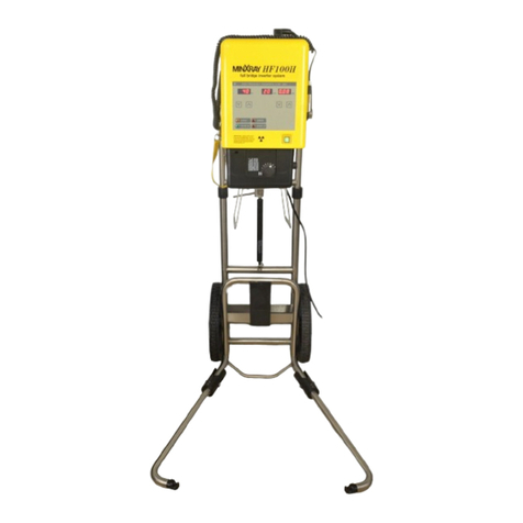
MinXray HF100H User manual

26 June 2002.
HF100H SERVICE MANUAL
This manual is established for repair・adjustment of the MinXray model HF100H portable x-ray
unit. Copy and transfer without notice is prohibited.
Section Contents Page
1.0 Introduction 1
2.0 Device history 2
3.0 Specifications 3
4.0 Operating procedures 5
5.0 Pre-adjustment 7
6.0 Re-adjustment of kV 11
7.0 Re-adjustment of Pre-heat time and mA 13
8.0 Re-adjustment of exposure time 16
9.0 Sample of output waveform 17
10.0 Trouble shooting Guide 18
11.0 Wiring diagram 22
12.0 Schematic Diagram 23
13.0 HF100H Parts List 27
14.0 Collimax Collimator operator’s 28
installer’s manual
15.0-1 Pre-adjustment with HF Tester 40
15.0-2 Pre-adjustment without HF Tester 41

1.0 Introduction
This service manual is for the MinXray model HF100H x-ray unit.
If you have any questions or need further assistance, please contact us. We are available Monday
- Friday, 8:30 - 17:00 Central Time.
Service Department
MinXray, Inc.
3611 Commercial Avenue
Northbrook, Illinois 60062-1822
U.S.A.
Tel: 1-847-564-0323
Toll free tel: 1-800-221-2245 (U.S. and Canada)
Fax: 1-847-564-9040
E-mail: service @ minxray.com
Internet: www.minxray.com
Alwa Always connect the power cord to a grounded AC mains electrical outlet.
High High voltage is present in some internal components.
X-radiation is emitted during some calibration tests described within this manual.
Observe radiation safety precautions when conducting these tests.
CARELESS OR IMPROPER USE OF X-RAY EQUIPMENT CAN BE EXTREMELY HAZARDOUS.
It is imperative that this equipment be operated and serviced only by trained personnel familiar
with the safety precautions required to prevent excessive exposure to primary and secondary
radiation, the dangers of exposure to x-radiation, and the proper use of the equipment and
instrumentation discussed in this manual. All personnel authorized to operate or service this
equipment should be fully acquainted with the established maximum permissible doses, safety
recommendations and procedures for working with high voltage components, and testing and
calibration instrumentation.
Although this x-ray unit incorporates protective design features for limiting both the direct
(primary) x-ray beam and the secondary radiation produced by this beam, design factors alone
cannot prevent human carelessness, negligence, or lack of knowledge. This apparatus is sold with
the understanding that the user assumes sole responsibility for radiation and electrical safety, and
that MinXray, Inc., its agent and representatives, do not accept any responsibility for:
1. Injury or danger to patient or other personnel from x-ray exposure or electrical shock.
2. Overexposure due to poor operating techniques or procedures.
3. Equipment not properly serviced, installed, or maintained in accordance with operation and
service manuals.
4. Equipment which has been modified or tampered with in any way.
-1-

2.0DEVICEHISTORY
Item No. Contents Start S/No.
1 Pre- production 19716
2 Solder Lead on the insert 21192
3 Making 8 screws lock tighter for out case 21545
4 Fixing the nut of PCB M9110 by bond (KE42) 23232
5 Using PCB M3107-B 23232
6 Adding the label 23232
Dangerous Voltage & Ionizing Radiation
7 Adding the fixing metal for insert 23539
8 Adding the fixing metal for collimator 23539
9 Changed the insert for balance collimator 25150
(D-180HS-G)
NOTE : The parts list is used from MinXray HF100H ( S/No. 25150)
-2-

3.0SPECIFICATIONS
POWER : Range --------------------------------------------
Minimum voltage with no load ---------
Maximum voltage with no load --------
Frequency -------------------------------------
Electricity consumption ------------ ------
Maximum voltage consumption --------
100 〜130VAC, 200 〜260VAC
100VAC, 200VAC
140VAC, 280VAC
50/60Hz
Minimum Maximum
110V 16A(40kV) 30A(100kV)
220V 8A(40kV) 15A(100kV)
3.5kVA ±10%
NOTE : This unit would be severely damaged if it is used with incorrect line voltage.
Check the rating label on the HF100H for the correct input voltage for each unit.
OUTPUT : Inverter : 120kHz high frequency inverter system with neutral ground
circuit,2kW ・60kHz inverter.
tube potential feedback system
tolerance ±10%
Filamentcircuit:0.5Watt ・45kHz inverter
tube current feedback system
tolerance ±10%
pre-heattime: approximately2sec.
WARM UP TIME : Approximately 10 seconds after each exposure and after the initial Power-on.
X-RAY OUTPUT : Maximum tube voltage : 100kV ±10%
Minimumtubevoltage: 40kV ±10%
kVswitch: 2kVsteps
Tubecurrent: 20mAconstant ±10%
Timerrange: 0.08–4.00sec. 0.01sec.steps
Tolerance ±10%
X-RAY TUBE : TOSHIBA D-124S
focalspotsize: 1.2mm×1.2mm
target material : tungsten
angle: 16°
anode heat storage capacity : 14kJ (20.0kHU)
COLLIMATOR : Collimax model D-180HS-G
Continuously adjustable light beam type with central ray indicator, and
cassette size/distance indicator to aid in correct positioning.
Ontime: 30sec.
Bulb : Philips No.6550 15V150W
Blublife: longerthan50hours
Illuminance : over 160 lux at 1 m SID
Contrast ratio : over 3:1 at 1 m SID
-3-

NOTE: Please refer to Collimator Operator’s and installer’s manual ( Page 20)
FILTRATION: inherentfiltration 2.2mmAl
collimator filtration 1.2mm Al
totalfiltration 3.4mmAl
WEIGHT : 20kgs
SIZE: 29cm(W) ×23.8 cm (H) ×45.5 cm (L)
POWER CORD : 3.6 m
EXPOSURE SWITCH : two stage, 3.0 m
-4-

4.0 OPERATING PROCEDURES
CONNECTION : After confirming POWER CORD and EXPOSURE SWITCH are intact, securely
connect them to main body of x-ray unit.
(If connector has lock, confirm it is locked.)
Confirm POWER SWITCH is OFF and connect POWER CORD to wall outlet or
wall socket of proper mains.
(When you use an extension cord, 3.5kW should be obtained.)
POWER ON : Set POWER SWITCH on control panel to ON. Each indicator will illuminate.
When the unit is warming up (WARM UP indicator is lit), exposures can not be
taken. Afterapprox.10sec.,
WARM UP indicator will go off. The unit is now ready to use.
DO NOT SWITCH ON AND OFF QUICKLY IN A SHORT TIME. WHEN
TURNING ON AGAIN AFTER TURNING OFF, WAIT FOR AT LEAST 1
MINUTE. OTHERWISE, THE HIGH FREQUENCY INVERTER CANNOT
WORK PROPERLY.
kV SETTING : Set kV in the range of 40kV to 100kV.
TIMER SETTING : Set timer in the range of 0.08 sec. to 4.00 sec. depending on subject, distance
and screen/film combination. Time increments are 0.01 sec. per step.
SOURCE-IMAGE DISTANCE:
Use the tape measure on the side of the HF100H to confirm that the x-ray
unit is positioned at the correct source-image distance (SID) for the view
being taken.
ADJUSTMENT OF RADIATION FIELD :
Pressing the collimator switch will illuminate the field for approx. 30sec.
Adjust light field to position of radiograph by two knobs for adjustment of
opening.
During this time, use the adjustment knobs to size the radiograph as you need.
RADIOGRAPHY :
Make sure that WARM UP indicator is OFF before pressing the exposure
switch.
WARM UP INDICATOR TURNS OFF 10 SEC. AFTER POWER ON.
WARM UP INDICATOR TURNS OFF 10 SEC. AFTER EACH EXPOSURE.
IF WARM UP INDICATOR IS ON, X-RAY EXPOSURE IS IMPOSSIBLE.
Make sure all WARNING LAMPS are off.
After all safety checks, press only first stage of EXPOSURE SWITCH.
STANDBY indicator goes off after 1 sec. Then, unit is ready for exposure.
Press and hold the second stage of EXPOSURE SWITCH. X-RAY indicator
illuminates, the buzzer sounds, and x-ray is generated for the time set. The
EXPOSURE SWITCH is a DEADMAN style. If the button is released, exposure
is stopped. So, press and hold the button until exposure is complete.
WARM UP indicator will light after exposure.
-5-

NOTE : The first stage of EXPOSURE SWITCH is pre-heat of filament.
DON’T KEEP ONLY THE FIRST STAGE OF EXPOSURE SWITCH “ON” LONGER
THAN 30 SEC.
POWER OFF : When the POWER SWITCH is pressed, all indicators on the control panel
are off.
WARNING LAMP : HF100H has 2 kinds of warning lamps. If either of them is lit, x-ray cannot
be generated. Each detail is as follows.
WARNING LAMP DETAILS COUNTERMEASURE
WARM UP
The internal circuit is
warming up.
Wait until light goes off.
ERROR
Unit malfunction.
Stop procedure and follow
steps below.
※ If ERROR indicator is lit even when EXPOSURE SWITCH BUTTON is released, it means an
unusual situation has occurred. Turn off POWER SWITCH, wait 3 minutes, then start
procedures over again.
※ This unit generates x-ray by an inverter. Therefore, it requires warm up time to be stable
after power on and each exposure. When WARM UP indicator is off, warm up is finished.
-6-

5.0 Pre-adjustment (Refer to page 40, page 41)
※Each PC Board delivered from the factory has already been adjusted.
1. 24VDC power supply adjustment (SVB24SA)
Check output (DCV) at Red (+) and Black (–) wires. Adjust VR on the SVB24SA to be C24V±
0.3V.
2. M3108A adjustment (Refer to page 8 )
kV adjustment : kV is decreased by turning clockwise.
1. This adjustment requires the special test equipment ( HF Tester).
2. Check the DC voltage between the kV (+) and GND on the test equipment ( HF Tester).
3. Set the kV selector to 100kV and turn VR1 so that the DC Voltage is 5.0V.
4. Check the voltage at each kV setting.
5. Finally check the kV by using an external kV tester such as the VICTOREEN NERO.
The reading will indicate a little lower than the actual output because of the tester
dynamics for high frequency x-ray production, so don’t adjust over 99kV indicated by
testing device.
mA adjustment : mA is decreased by turning clockwise.
1. This adjustment requires the special test equipment ( HF Tester).
2. Check the DC voltage between the mA (+) and GND on the test equipment ( HF Tester)..
3. Confirm the mAindicator to be 20mA and turn VR5 so that the DC Voltage is 2.0V.
Exposure time adjustment : Exposure time is decreased by turning clockwise.
Time base is 100Hz (10msec.). When jumper of JP2 is pulled out, X-RAY LED is lit without
relating to timer. Measure voltage between TIME test point and GND test point by
Oscilloscope, and adjust by VR6.
IMPORTANT : Disconnect the connector JP2 on M3108A PCB
before removing the jumper of X-RAY. Otherwise, Inverter PC
Board will work and X-RAY will be generated unrelated to timer
setting and X-RAY unit might be damaged.
※Pull in and pull out connectors only with MAIN POWER OFF.
↑
12V
↓
←10mS →
※TIME BASE WAVEFORM
NOTE : Please contact MinXray, Inc. ( Service Department ) if you need information of the
special test equipment (HF Tester).
-7-

REFFERENCE : There are three jumpers on M3108A (10SEC ,TEST and LBD)
10SEC: When jumper is put in, WARM UP time is 1 sec. DO NOT
USE. When jumper is pulled out, it is 10 sec.
This jumper is for adjustment at the factory before shipment.
So, please don’t use the device with jumper.
TEST : ※NEVER PULL OUT THIS SHORT PIN. X-RAY WILL BE
GENERATED PERMANENTLY AND DANGEROUSLY.
LBD: Not used
3. M9111 PC Board adjustment (refer to page 9)
It can adjust the following:
※Over Voltage Protection circuit (VR1)
※Over Current Protection circuit (VR2)
※DC voltage adjust circuit (VR3)
Calibrated DC voltmeter is necessary.
4. M9112 PC Board adjustment (refer to page 10)
It can adjust the following:
※Frequency of Inverter PC Board (VR1)
※Pre-heat time for Low mode (VR3)
※kV (VR4)
※mA (VR5)
-8-

M9111 PC Board adjustment
This adjustment has to be done after connecting all connectors completely.
Actual x-ray exposure is not necessary.
※Each PC Board delivered from the factory has been already adjusted.
1. Adjustment of VR3 (DC370V)
Adjust voltage between 370 (+) and GND (–) to be 368.5 – 372V by turning VR3.
Voltage is increased by turning clockwise.
2. Adjustment of VR2 (Over Current Protection circuit)
Adjust voltage between OCP(+) and GND (–) to be 1.09 – 1.11V by turning VR2.
Voltage is increased by turning clockwise.
3. Adjustment of VR1 (Over Voltage Protection circuit)
Adjust voltage between OVP (+) and GND (–) to be 2.4 – 2.45V by turning VR1.
Voltage is decreased by turning clockwise.
-9-

M9112 PC Board adjustment
This adjustment has to be done after connecting all connectors completely. Actual
x-ray exposure is not necessary.
※Each PC Board delivered from the factory has been already adjusted.
1. Adjustment of FQ1
Adjust frequency between FQ1 (+) and GND (–) to be 120kHz by turning VR1.
Frequency is increased by turning clockwise.
2. Confirmation of FQ2
Confirm if frequency between FQ2 (+) and GND (–) is 90kHz ±5%. It cannot be adjusted.
3. Adjustment of Pre-heat voltage at 20mA.
Adjust voltage between PRE (+) and GND (–) to be 0.43V by turning VR3.
Voltage is increased by turning clockwise.
4. Set VR4 (EP SET) to the center position.
5. Set VR5 (IP SET) to the center position.
-10-

6.0 Re-adjustment of kV
This adjustment has to be done after connecting all connectors completely.
Actual exposure is necessary.
NOTE : This adjustment requires that an exposure be made. Please observe all radiation
related safety precautions.
※This adjustment should be done whenever Insert Box or Inverter PC Board (M9101B PCB) is
replaced.
Oscilloscope (with storage mode) : Connect CH1 probe to EP, CH2 probe to IP, and GND to GND
terminal on M9112 PC Board. (refer page 9)
Setting of oscilloscope : CH1 ; 1V/div, CH2 ; 0.5V/div, 10msec/div
Settingofx-raydevice: 0.1sec., 70kV
Place of adjustment : VR4 on M9112 PC Board (EP SET)
Method of adjustment : Measure x-ray tube voltage by oscilloscope and adjust average
of peak values of EP waveform to be 3.4V by VR4.
After the adjustment is finished, set of device to be 100kV and
adjustagainsothataverageofpeakvaluesofEPwaveformto
be 4.9V.
.
When x-ray tube voltage is measured by non invasive direct x-ray measuring
equipment such as NERO, approx. 3kV of deviation is included. Therefore,
adjust kV to be 97.5 〜99kV at 100kV station.
-11-

5 – 1. Adjustment of 70kV by VR4
Adjust the ch1 (Ep) by VR4 to be 3.4V ±0.5V. kV is increased by turning clockwise.
5 – 2. Adjustment of 100kV by VR4
Adjust the ch1 (Ep) by VR4 to be 4.9V ±0.5V. kV is increased by turning clockwise.
-12-

7. 0 Re-adjustment of Pre-heat and mA
This adjustment has to be done after connecting all connectors completely.
Actual exposure is necessary.
NOTE : This adjustment requires that an exposure be made. Please observe all radiation
related safety precautions.
*This adjustment should be done whenever Insert Box or Inverter PC Board (M9112 PCB) is
replaced.
Oscilloscope (with storage mode) : Connect CH1 probe to EP, CH2 probe to IP, and GND to GND
terminal on M9112 PC Board. (refer page 9)
Setting of oscilloscope : CH1 ; 1V/div, CH2 ; 1V/div, 10msec/div
Setting of x-ray device : 0.1 sec., 80kV
Place of adjustment : VR3 (Pre-heat voltage) ・VR5(mA)
VR3:adjustmentofPre-heattimeat25〜20mA.
(Pre-heat time is shorten by turning clockwise.)
VR5 : set 20mA and adjust to be 19mA
※Pre-heat time should be adjusted to be 30msec.±10msec.
-13-

6 –1. Adjustment of Pre-heat time
1. Pre-heat time is short. Make Pre-heat time longer by turning VR3 counterclockwise.
2. Pre-heat time is long. Make Pre-heat time shorter by turning VR3 clockwise.
3. Pre-heat time is appropriate.
※Acceptable limit : 20msec. 〜40msec.
-14-

6 –2 – 1. Adjustment of mAby VR5
※Adjust average of peak values of IP waveform to be 1.9V by VR5.
-15-

8.0 Readjustment of exposure time
This adjustment has to be done after connecting all connectors completely.
Actual exposure is necessary.
NOTE: This adjustment requires that an exposure be made. Please observe all radiation
related safety precautions.
Check the exposure time by using an external exposure time meter such as the VICTOREEN
NERO.
X-ray unit setting: 82kV ・0.5sec
Adjustment: Exposure time is decreased by turning clockwise. (VR6 on the M3108A PC board)
-16-

9.0 Sample of output waveform
Normal waveform
100kV ・ 20mA
-17-

10.0-1 Trouble shooting Guide
-18-

10.0-2 Trouble shooting Guide
-19-
Other manuals for HF100H
2
Table of contents
Other MinXray Medical Equipment manuals
Popular Medical Equipment manuals by other brands

Bedfont
Bedfont NOBreath operating manual

Cyclomedica
Cyclomedica TechnegasPlus Technegas 25000 user manual

Otto Bock
Otto Bock Genium X3 Series Instructions for use

Braun
Braun Aesculap Instructions for use/Technical description

HiTRAx
HiTRAx 42.7007 operating instructions

Electronique du Mazet
Electronique du Mazet ECHODIA Babyscreen Instructions for use and Technical description