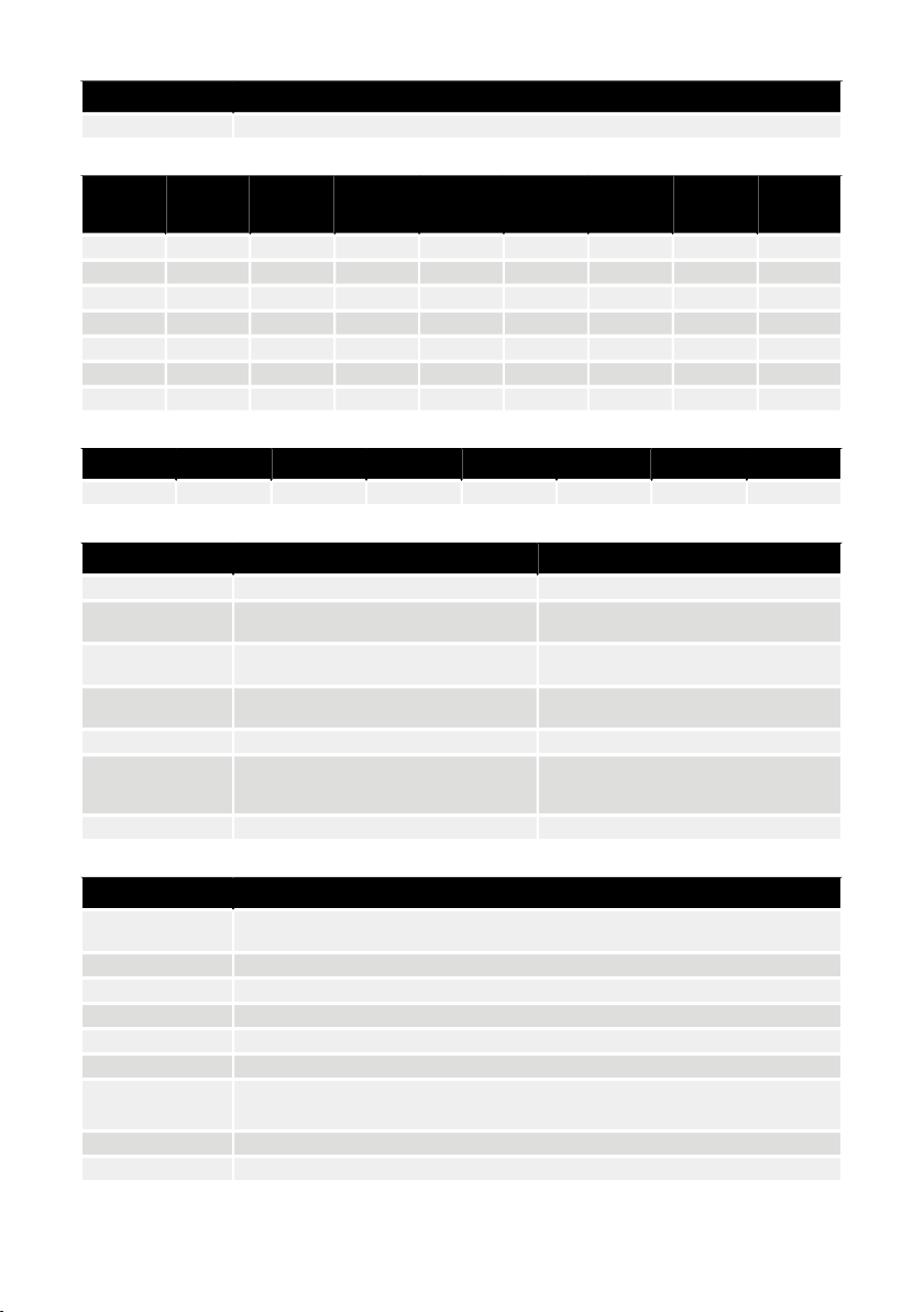
Hilscher NT 50-RS-EN adapter cable pinout (female DSUB-9)
DescriptionPIN (colour)
GND1 (white, WH)
Modbus RTU (A, RxD / TxD+)4 (brown, BN)
Modbus RTU (B, RxD / TxD–)5 (green, GN)
ShieldSHIELD
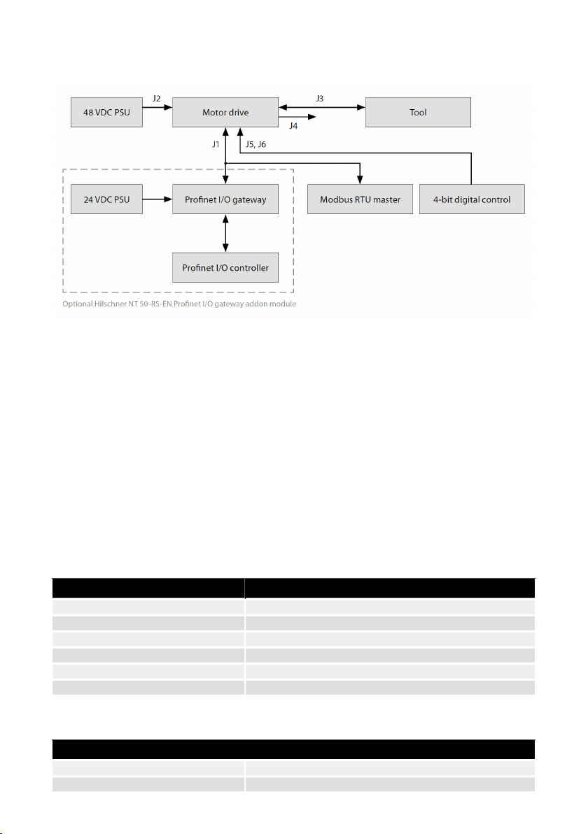
Modbus RTU
Modbus RTU over RS-485 is used to communicate with the motor drive. The motor drive is configured as a Modbus RTU
slave device and the default slave address is 86. The slave address can be changed if it conflicts with another Modbus
RTU slave device.
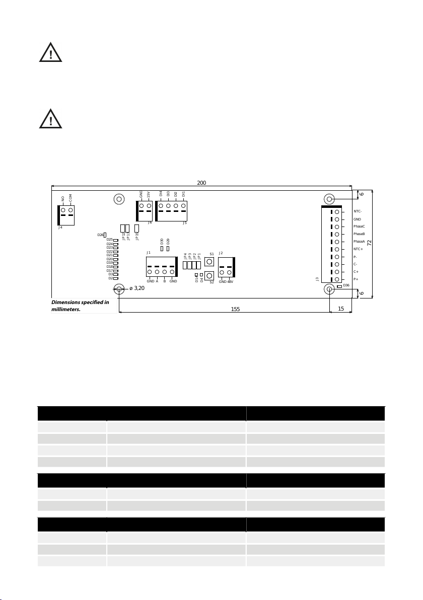
The J1 connector on the motor drive is used for Modbus RTU communication. A shielded twisted pair cable is recommended
and the shield should be earthed only at one point, normally at the master device. The A-pin of the J1 connector is
equivalent to RxD / TxD+ and the B-pin is equivalent to RxD / TxD–.
RS-485 configuration
19200BAUD RATE
EVENPARITY
1STOP BITS
8DATA BITS
Coil registers (F1, F5, F15)
DesciptionNameData typeAddress
Coils 1–11 are reserved for future
use.
Digital outputsUint1600001 - 00012
Coil 12 is the relay located on the
motor drive.
Input registers (F4)
DescriptionNameData typeAdress
The number of times the speed
has dropped from set-point by
more than 25%.
Drop RPM countUint1630001
The number of times the tool
temperature has exceeded the
“warm”limit, 79°C.
Warm tool countUint1630002
The number of times the motor
drive temperature has exceeded
the “warm”limit, 73°C.
Warm motor drive countUint1630003
The number of times the tool
temperature has exceeded the
“hot”limit, 134°C.
Hot tool countUint1630004
The number of times the motor
drive temperature has exceeded
the “hot”limit, 117°C.
Hot motor drive countUint1630005
The number of times the tool
temperature has exceeded the
“stop”limit, 142°C.
Stop tool countUint1630006
The number of times the motor
drive temperature has exceeded
the “stop”limit, 123°C.
Stop motor drive countUint1630007
9
en (original)