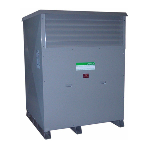
Mirus AUTOTRANSLINEATOR Technical Document

MIRUS International Inc. INSTALLATION,
OPERATION AND
MAINTENANCE GUIDE
AUTOTRANSLINEATOR™
AUTOTRANSFORMER AND UNIVERSAL HARMONIC FILTER
ATL-M001-A2

AUTOTRANSLINEATOR™
ii ATL-M001-A1
IMPORTANT SAFETY INSTRUCTION
SAVE THESE INSTRUCTIONS - This manual contains important instructions for the AutoTransLineatorTM
that must be followed during installation, operation, and maintenance of the AutoTransLineatorTM and its
auxiliary equipment.
WARNING
OPENING ENCLOSURES EXPOSES HAZARDOUS VOLTAGES.
ALWAYS REFER SERVICE TO QUALIFIED PERSONNEL ONLY.
WARNING
As standards, specifications, and designs are subject to change, please ask for
confirmation of the information given in this publication.
This manual is a controlled document; pages should not individually be removed from
this document.

ATL-M001-A2 iii
MIRUS International Inc.
AUTOTRANSLINEATOR™
INSTALLATION, OPERATION AND
MAINTENANCE GUIDE
ATL-M001-A2
3-Feb-2010
MIRUS International Inc.
31 Sun Pac Blvd.
Brampton, Ontario
Canada L6S 5P6
1 - 888 - TO – MIRUS (1 - 888 - 866 – 4787)
Tel: (905) 494-1120
Fax: (905) 494-1140
Website: www.mirusinternational.com

AUTOTRANSLINEATOR™
iv ATL-M001-A2
Warranty and Performance Guarantee
1. Warranty: MIRUS International Inc. (“MIRUS”) warrants to the end-user (the “Customer”) of the AUTOTRANSLINEATOR™
Harmonic Filter (“ATL”) as follows:
(a) The AUTOTRANSLINEATOR™ATL will be free from defects in materials and workmanship under normal use and service for a
period of 3 years from the date of shipment; and
(b) The AUTOTRANSLINEATOR™ATL will perform as advertised to reduce harmonic distortion caused by AC Variable Speed
Drives and other non-linear loads equipped with 3-phase, 6-pulse, diode bridge rectifiers. A properly selected and installed
AUTOTRANSLINEATOR™will:
(i) Reduce Current Total Harmonic Distortion (ITHD), measured at the AUTOTRANSLINEATOR™input terminals at full
load, to:
• < 8% when background voltage distortion is < 5% and voltage imbalance is < 3%
• < 5% when short circuit ratio (Isc/IL), as defined by IEEE Std 519, is < 20 and when background voltage distortion
is < 0.5% and voltage imbalance is < 1%
(ii) Reduce Current Total Demand Distortion (ITDD), measured at the AUTOTRANSLINEATOR™input terminals over its
entire operating range, to levels defined in Item 1 above. ITDD is defined as the measured ITHD multiplied by the ratio
of measured RMS current to full load current (peak demand current) of the AUTOTRANSLINEATOR™.
(iii) Minimize the contribution to Voltage Harmonic Distortion of all VSD’s equipped with the AUTOTRANSLINEATOR™to <
5% total and < 3% for individual harmonics, as defined by IEEE Std 519-1992.
(iv) NOT become overloaded by other upstream harmonic sources.
(v) NOT resonate with other power system components.
(vi) NOT have compatibility problems with engine generator sets properly sized for the load.
2. Limitation: Limitation: The foregoing warranties shall not apply and shall be void if the AUTOTRANSLINEATOR™ATL has
been subject to misuse, abuse, accident, disaster, or has been operated contrary to MIRUS’ instructions relating to installation,
maintenance, use or operation.
3. Exclusive Remedy: If the AUTOTRANSLINEATOR™ATL does not conform with the warranties set out above, the Customer
must notify MIRUS of the defective unit within the applicable warranty period and obtain a written return material authorization
(an “RMA”) from MIRUS. The Customer must return the defective unit to MIRUS, freight prepaid, within sixty (60) days of
receipt of the RMA and must include a copy of MIRUS’ paid invoice for the defective unit and a description of the defective
unit’s failure to conform. If MIRUS agrees that the returned unit is defective, MIRUS’ entire obligation and liability shall be, in
MIRUS’ sole discretion, to repair or replace the defective unit or give a full refund of the purchase price to the Customer.
THE FOREGOING IS THE CUSTOMER’S SOLE AND EXLUSIVE REMEDY FOR BREACH OF WARRANTY BY MIRUS WITH
RESPECT TO THE AUTOTRANSLINEATOR™ATL.
4. Replacement or Repaired Product Warranty: Any repaired or replaced AUTOTRANSLINEATOR™ATL shall be warranted as
set forth herein for the remainder of the applicable warranty period of the original unit or for three (3) months, whichever is
greater.
Service and Factory Repair - Call 1 - 888 - TO - MIRUS (1 - 888 - 866 – 4787)
Direct questions about the operation, repair, or servicing of this equipment to MIRUS International Inc. Customer Support
Services. Include the part number, assembly number, and serial number of the unit in any correspondence. Should you require factory
service for your equipment, contact MIRUS International Inc. Customer Support Services and obtain a Return Materials Authorization
(RMA) prior to shipping your unit. Never ship equipment to MIRUS International Inc. without first obtaining an RMA.
Proprietary Rights Statement
The information in this manual is the property of MIRUS International Inc., and represents a proprietary article in which MIRUS
International Inc., retains any and all patent rights, including exclusive rights of use and/or manufacture and/or sale. Possession of this
information does not convey any permission to reproduce, print, or manufacture the article or articles shown herein. Such permission may
be granted only by specific written authorization, signed by an officer of MIRUS International Inc.
AUTOTRANSLineator™ is a trademark of MIRUS International Inc. Other trademarks that may be used herein are owned by their
respective companies and are referred to in an editorial fashion only.
Revision History
Copyright © All rights reserved. Printed in Canada
Revision: A1 New Release 2009/06/18

Operation & Maintenance Manual
ATL-M001-A2 v
Contents
Section Description Page
1.0 Installation ……………………………………………. 1
1.1 Location ………………………………………………. 1
1.2 Inspection …………………………………………….. 1
1.3 Handling ………………………………………………. 1
1.4 Grounding …………………………………………….. 1
2.0 Storage ………………………………………………… 1
3.0 Maintenance …………………………………………... 2
3.1 Periodic Inspection and Maintenance ……………… 2
3.2 Cleaning ……………………………………………….. 2
3.3 Drying of Core and Coil Assembly ………………….. 2
4.0 Operation ………………………………………………. 3
4.1 Effect of Humidity ……………………………………… 3
4.2 Loading …………………………………………………. 3

AUTOTRANSLINEATOR™
vi ATL-M001-A2

Operation & Maintenance Manual
ATL-M001-A2 1
1.0 Installation
1.1 Location
Location of the AUTOTRANSLINEATOR™should be
made with consideration given to accessibility,
ventilation and atmospheric conditions. Sufficient
clearances from walls and other obstructions
should be provided to permit unrestricted opening
of hinged and removable doors, covers and
panels for the purpose of wiring terminations,
inspection, maintenance and testing. Also, proper
ventilation requires at least 6 in. (155mm)
clearance at all ventilation openings. In enclosed
rooms, minimum air circulation of 100 ft3/ min per
kilowatt of transformer loss should be provided.
Installation locations should be free of
contaminants including dust, fertilizer, excessive
moisture, corrosive gases, flammable materials or
chemical fumes. Filtered air may be considered to
reduce maintenance where air born contaminants
are a problem.
Enclosures are designed in accordance with
NEMA and UL standards and can allow for
installation in various environments. Standard
enclosures for the AUTOTRANSLINEATOR™are
NEMA3R and NEMA3R Enhanced.
Where AUTOTRANSLINEATORS™are connected to
lines subject to lightning exposure or other voltage
surges, careful coordination of BIL levels and
protective surge arresters must be made. For
derating factors which apply to installation at high
altitudes, refer to ANSI C57.12.01-1989.
1.2 Inspection
Upon receipt of shipment the
AUTOTRANSLINEATOR™should be inspected for any
damage incurred during shipment. Before
energization an internal inspection should be
conducted with emphasis on loose or broken
connections, damaged or displaced parts, cracked
insulators, dirt or foreign material, or evidence of
moisture.
1.3 Handling
The AUTOTRANSLINEATOR™should be thoroughly
protected against the entrance of dust, rain or
snow when handled outdoors.
When lifting the AUTOTRANSLINEATOR™, the lifting
cables should be held apart by a spreader to avoid
bending the lifting lugs or other parts of the
structure. The AUTOTRANSLINEATOR™may be
skidded or moved on rollers but care must be
taken not to damage the base or tip it over. When
rollers are used under larger units, skids must be
used to distribute the stress over the base.
After the AUTOTRANSLINEATOR™is placed in
permanent position, shipping braces should be
removed and shipping bolts, if present, should be
loosened. Where isolation pads have been
included, the bolt should be loosened until the
spring washer has been relaxed before putting
into service. This will reduce noise resulting from
the AUTOTRANSLINEATOR'S™natural vibration.
1.4 Grounding
Consideration must be given to equipment
grounding (case and core) and must be made in
accordance with all applicable electrical codes.
2.0 Storage
Condensation and moisture absorption must be
prevented during storage. The
AUTOTRANSLINEATOR™must be stored in a warm,
dry location. Ventilation openings should be
covered to keep out dust. If outdoor storage
cannot be avoided, the AUTOTRANSLINEATOR™
must be protected to prevent entrance of water,
moisture and foreign material.
WARNING
Danger! There is the potential of
electric shock whenever working
in or around electrical equipment
such as transformers. Power must
be shut off before any work is
conducted on a transformer.

AUTOTRANSLINEATOR™
2 ATL-M001-A2
3.0 Maintenance
WARNING
Internal maintenance must be
performed with a transformer de-
energized, isolated and with the
terminals grounded.
3.1 Periodic Inspection and Maintenance
The AUTOTRANSLINEATOR™has no moving or
active parts and therefore requires only minimal
periodic maintenance when installed in a clean
and well ventilated environment. This should
include:
3.1.1 Visual inspection for evidence of loose
connections, dirt, moisture, rusting,
corrosion, and deterioration of the
insulation, varnish or paint.
Observations should be made for signs
of overheating and overvoltage creeping.
Corrective measures should be taken as
necessary.
3.1.2 For early detection of any developing
hotspots, an infrared scan can be
performed while the
AUTOTRANSLINEATOR™is operating under
its heaviest load condition.
3.1.3 Measuring the current in each of the 3
phases of the capacitor circuit can be a
quick and easy method of determining
the condition of the capacitors. The
capacitors can be assumed to be in good
operating condition when all 3 phases
carry approximately the same amount of
load current. Measurements should be
taken at the input to the capacitor fuse
block and can be done at any loading
condition. If the phase currents are found
to be substantially different, the unit
should be taken offline and serviced by a
qualified technician. This test should be
conducted annually or whenever the unit
seems to be operating in an abnormal
manner.
3.2 Cleaning
Excessive accumulations of dirt on the transformer
windings or insulators and capacitor terminals
should be removed to permit free circulation of air
and to guard against the possibility of insulation
breakdown. Particular attention should be given to
cleaning the top and bottom ends of the winding
assemblies and to cleaning out ventilating ducts.
Windings should be lightly cleaned by the use of a
vacuum cleaner. If necessary a blower or
compressed air may be used but pressure should
not exceed 25 psi. Lead supports, tap changers
and terminal boards, bushings, and other major
insulating surfaces should be brushed or wiped
with a dry cloth. The use of liquid cleaners is not
recommended due to deteriorating effects on most
insulating materials.
3.3 Drying of Core and Coil Assembly
CAUTION
Constant attention during the
drying process is recommended.
When it is necessary to dry a
AUTOTRANSLINEATOR™transformer before
installation or after an extended shutdown under
relatively high humidity conditions, internal and/or
external heating methods can be used. (See
ANSI/IEEE C57.94-1982 for a description of these
methods).
It is important that most of the heated air pass
through the winding ducts and not around the
sides. Good ventilation is essential in order that
condensation not take place in the reactor itself or
inside the case. A sufficient quantity of air should
be used to assure approximately equal inlet and
outlet temperatures.
Air temperature should not exceed 70°C.

Operation & Maintenance Manual
ATL-M001-A2 3
4.0 Operation
WARNING
Internal maintenance must be
performed with a transformer de-
energized, isolated and with the
terminals grounded.
Caution: Do not remove covers, panels, or any
enclosure parts while the AUTOTRANSLINEATOR™is
energized.
4.1 Effect of Humidity
While the AUTOTRANSLINEATOR™is energized,
humidity conditions are generally not important
since the heat from the reactor will prevent
condensation. If a shutdown exceeding 24 hours
occurs during a period of high humidity that could
cause condensation within the transformer,
precautions should be taken. Small strip heaters
may be energized in the bottom of the unit to
maintain the temperature of the unit a few degrees
above that of the outside air. If such precautions
are not taken the unit should be inspected for
evidence of moisture and insulation resistance
checked. If necessary, dry as described in
Maintenance section above.
4.2 Loading
AAUTOTRANSLINEATOR™should only be loaded in
accordance with its nameplate rating.

AUTOTRANSLINEATOR™
4 ATL-M001-A2
NOTES

Operation & Maintenance Manual
ATL-M001-A2 5

MIRUS International Inc.
31 Sun Pac Blvd.
Brampton, Ontario
Canada L6S 5P6
1 - 888 - TO – MIRUS (1 - 888 - 866 – 4787)
Tel: (905) 494-1120
Fax: (905) 494-1140
Website: www.mirusinternational.com
Table of contents
Other Mirus Water Filtration System manuals
Popular Water Filtration System manuals by other brands

WET
WET CAK Series Installation, operation and maintenance manual

Aquaport
Aquaport AQP-16AO user manual

Watts
Watts 70684 Series installation manual

Pittsburgh Automotive
Pittsburgh Automotive 93980 Instructions and precautions

Katadyn
Katadyn 8013629 user guide

NKT Photonics
NKT Photonics SuperK SPLIT Product guide

Peachtree Woodworking Supply
Peachtree Woodworking Supply 530 instructions

Omnitec
Omnitec OmniAire 1000 Series Operation and maintenance manual

Harris
Harris 156593 Installation, operation & parts

King Industrial
King Industrial KDCF-8300 instruction manual

ProfiDrum
ProfiDrum 65 user manual

EHEIM
EHEIM PowerPack 2252 instructions