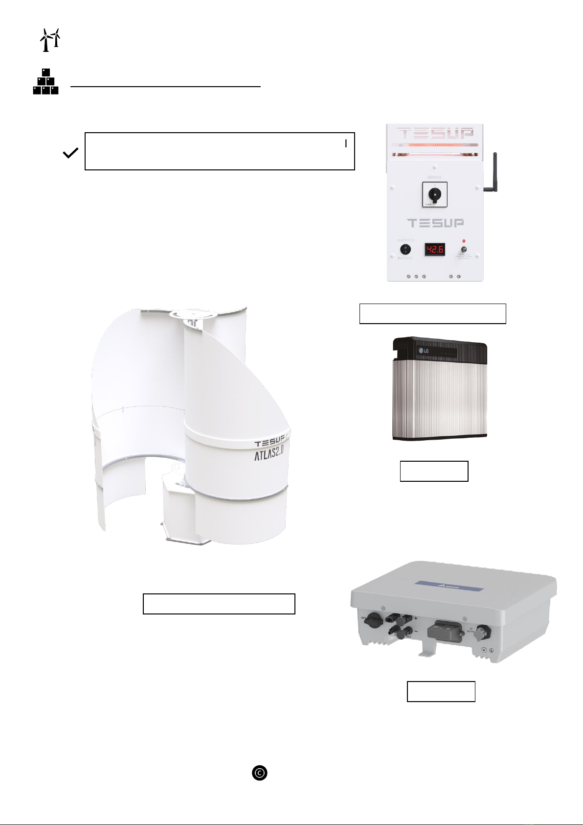
ATLAS 2.0 (MADE IN EUROPE)
~ 8 ~
TESUP
3.1 INTENDED USE:
▪The wind turbine system may only be used as a “small wind turbine system” (SWTS) to
generate power in accordance with EN 61400-2.
▪The wind turbine system may only be operated in accordance with the ratings and in the
approved wind class (refer to the technical data).
▪Observance of the original instructions and compliance with the maintenance and repair
instructions are essential preconditions of use for the intended purpose.
3.2 REASONABLY FORESEEABLE MISUSE:
▪All forms of use which deviate from or exceed the limits of use described above are
contrary to the intended purpose. The manufacturer is not liable for any damage resulting
from such use.
▪No liability will be accepted by the manufacturer if the equipment has been altered as well
as in the event of improper assembly, installation, start-up, operation, maintenance, or
repair.
▪Only original parts supplied by the manufacturer are approved as spare parts or
accessories. Any spare parts or accessories not supplied by the manufacturer have not
been tested for operation and could be detrimental to reliability. No liability will be
accepted by the manufacturer for any damages which result from the use of non-approved
spare parts or accessories.
▪Reasonably foreseeable misuse includes:
oOperation outside the manufacturer’s specification.
oAll modifications or changes to the wind turbine system without the
manufacturer’s written approval!
oUse of parts other than ATLAS 2.0 original parts.
oOperation in non-approved SWTS classes.
oOperation in strong winds or hurricanes.