manuals.online logo
Brands
  1. Home
  2. •
  3. Brands
  4. •
  5. Mitchell Golf
  6. •
  7. Tools
  8. •
  9. Mitchell Golf Steelclub User manual

Mitchell Golf Steelclub User manual

Thank You for purchasing the golf industry’s state-of-the-art STEELCLUB Irons Angle
Machine. You should find it simple to operate. Please follow the instructions in this manual.
Be sure to mount the stand into the floor and attach the machine before attempting to
use it. If you have any questions, please call 1-800-437-1314.
Your STEELCLUB Irons Angle Machine is a percision gauge.
When measuring a particular golf club in your STEELCLUB Irons Angle Machine, the
angle readings are correct. When these angle readings are compared to the published
standards for that club and are found dierent, then that particular club does not meet
those standards.
If you compare the loft/lie angles of a particular club measured in other machines to
a STEELCLUB Irons Angle Machine, there may be a dierence. That is because some
machines do not adjust for oset, progressive oset, non-oset, or face progression hosel
positions and therefore give inaccurate and inconsistent readings. You can measure any
club in a STEELCLUB Irons Angle Machine accurately.
All products manufactured by Mitchell Golf are guaranteed against defects and
workmanship. Replacement or repair will be at the discretion of Mitchell Golf.
Introduction ............................................................................................................................. 1-2
Table of Contents....................................................................................................................... 4
Package Contents.................................................................................................................. 5-7
Maintenance.............................................................................................................................. 8
Customer Support ...................................................................................................................... 8
Operating Instructions .................................................................................................................
Club Head Registration & Clamping ................................................................................ 9
Measuring Loft/Lie Angles................................................................................................ 10
Adjusting Loft/Lie Angles .................................................................................................. 11
Convert to Left Hand........................................................................................................ 12
STEELCLUB Irons Angle Machine
1. Clean occasionally with WD-40 to prevent corrosive build up.
2. Face Tape: As needed, clean o old tape on backside of Face Fixture and replace
with two new pieces of tape, cut approximately 2 1/2” long from the roll. Peel the
back o the tape and place on the backside of Face Fixture, directly above the Iron
Sole Clamps. Make sure tape is pressed on evenly by rubbing with a hard object,
such as a coin.
3. Keep a small amount of grease on the bottom end of the Top Worm Screw where it
makes contact with the Top Clamp.
4. Occasionally apply grease to the Top Worm Screw.
Call 1-800-437-1314
Monday-Friday 8:00AM-5:00PM Eastern Time
Email: [email protected]
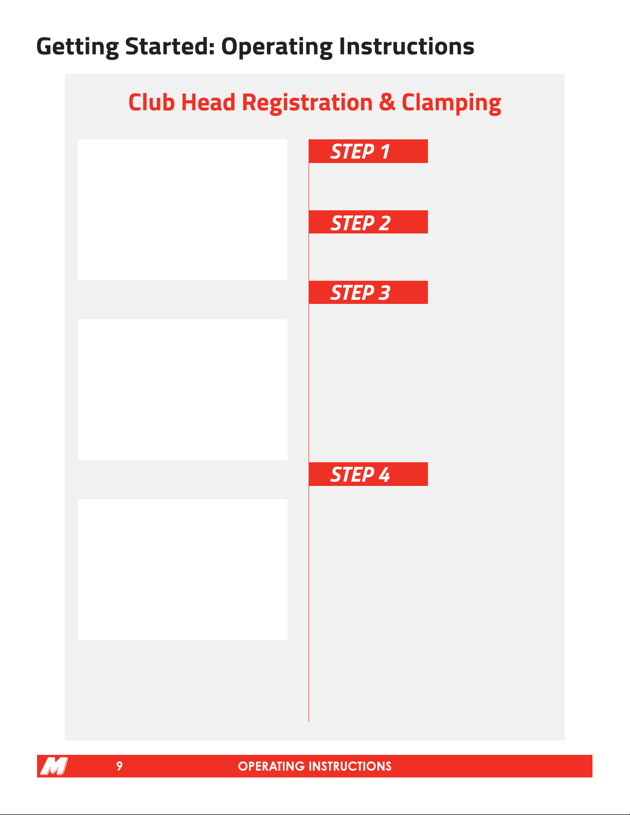
Push the Loft/Lie Gauge Assembly to the back of the
machine to allow room to insert the club head.
Loosen the Top Worm Screw that adjusts the Top Iron
Clamp that holds the iron head in place.
Insert club head into back of Face Fixture, setting the
club sole on the two Iron Sole Clamps and the toe of
the club touching the Toe Stop. Adjust club head so the
score lines are parallel to the Horizontal Dowel Pin that
is in between the Face Fixture by adjusting the Toe Stop
inward or outward. Make sure club head is flush against
the back of the Face Fixture then tighten the Top Worm
Screw. See illustrations 1 and 2.
If necessary use the T-Wrench to tighten the Back Iron
Clamp against the back of the iron sole.
See illustration 3.
NOTE: Use the Back Iron Clamp only when the club face
does not clamp flush against the Face Fixture or when
the club head slips when bending. These conditions are
caused by the sole design on only a few models of clubs.
Do not use the Back Iron Clamp on every iron. It will slow
down your bending time and is not necessary to use on
every club.
illustration 1
illustration 2
illustration 3
Slide the Loft/Lie Angle Gauge Assembly forward and
allow the Vertical Plate to tilt on its vertical axis until the
shaft is flush against it. Slide the Lie Angle Gauge up until
it is touching the shaft. See illustration 4.
Read the loft on the Loft Gauge directly below the word
“LOFT” as indicated at the lower right corner on the front
of the Vertical Plate. See illustration 5.
Read the lie angle on the Lie Angle Gauge. See
illustration 6.
illustration 4
illustration 5
illustration 6
Slide Loft/Lie Angle Gauge Assembly to back of
machine. Place adjustable bending bar on hosel as low
as possible. Adjust bar to snug fit (finger tight) by turning
knurled knob at end of bar. See illustration 7.
To bend hosel apply light pressure to bending bar in the
direction of desired bend until it is seated firmly against
hosel. Apply short, quick jolts of bending pressure to
bend hosel. Remeasure club and rebend if necessary
to desired angles.
To adjust lie angle bend up to make more upright and
down to make flatter. The shaft should move in a plane
parallel to the front of the machine. See illustration 8.
To adjust the loft angle bend back (up) to deloft the club
and bend forward (down) to add loft to the club. The shaft
should move in a plane parallel to the side of the machine.
See illustration 9.
illustration 7
illustration 8
illustration 9
Remove the Tension Bolt from Loft/Lie Angle Gauge
Assembly. Place entire assembly on left hand side of
machine over the two dowel pins exactly like it was on
the right hand side.
Replace the Tension Bolt by threading into the hole
between the two dowel pins. Make sure it is loose enough
to permit the Loft/Lie Angle Gauge Assembly to slide
back and forth.
Remove the Toe Stop from the left hand side of the Face
Fixture and screw it into the hole on the right hand side.
To measure and bend, repeat the same steps per
instructions on pages 9-11. Read the lie for left hand,
denoted by “L.H.” on the Lie Angle Gauge. Read the
loft on the Loft Gauge.

Popular Tools manuals by other brands

EIBENSTOCK KBS 250 Original instructions

EIBENSTOCK

EIBENSTOCK KBS 250 Original instructions

RIDGID 815A NPT instruction sheet

RIDGID

RIDGID 815A NPT instruction sheet

Lincoln 94000DS Series Owner's/operator's manual

Lincoln

Lincoln 94000DS Series Owner's/operator's manual

iKoustic MuteClip Installation guides

iKoustic

iKoustic MuteClip Installation guides

Berner 156014 manual

Berner

Berner 156014 manual

Nederman Series 532 instruction manual

Nederman

Nederman Series 532 instruction manual

Sealey AUTO SERVICE OFC1 instructions

Sealey

Sealey AUTO SERVICE OFC1 instructions

Draper P5 instructions

Draper

Draper P5 instructions

Fagor 100P installation manual

Fagor

Fagor 100P installation manual

DeWalt DCE200M2K instruction manual

DeWalt

DeWalt DCE200M2K instruction manual

EUROM EASYWINDER instruction manual

EUROM

EUROM EASYWINDER instruction manual

GARANT 080078 user guide

GARANT

GARANT 080078 user guide

SIP 03637 manual

SIP

SIP 03637 manual

Lankota CK1100 owner's manual

Lankota

Lankota CK1100 owner's manual

Matco Tools MST11880A manual

Matco Tools

Matco Tools MST11880A manual

OLI PS 40 Installation and operating instructions

OLI

OLI PS 40 Installation and operating instructions

ITATOOLS ITA 25 Operation manual

ITATOOLS

ITATOOLS ITA 25 Operation manual

Endo CRL-2000 Series instruction manual

Endo

Endo CRL-2000 Series instruction manual

manuals.online logo
manuals.online logoBrands
  • About & Mission
  • Contact us
  • Privacy Policy
  • Terms and Conditions

Copyright 2025 Manuals.Online. All Rights Reserved.