MITECH MH310 User manual

MITECH CO., LTD.
www.mitech-ndt.com

1
CONTENTS
1 Overview................................................................................................................................................................. 3
1.1 Advantages................................................................................................................................................ 3
1.2 Main Application &Testing Range.......................................................................................................... 3
1.2.1 Main Application.....................................................................................................................................3
1.2.2 Testing Range.........................................................................................................................................3
1.3 Technical Specifications...........................................................................................................................4
1.4 Configuration............................................................................................................................................. 4
1.5 Working Conditions...................................................................................................................................5
1.6 Safety Instructions.................................................................................................................................... 5
2 Structure Feature &Testing Principle............................................................................................................. 5
2.1 Structure Feature...................................................................................................................................... 5
2.1.1 The Hardness Tester Appearance...................................................................................................... 5
2.1.2 Parts of the Main body.......................................................................................................................... 6
2.1.3 D Type Impact Device...........................................................................................................................7
2.1.4 Different Types of Impact Device........................................................................................................7
2.2 Main Screen...............................................................................................................................................7
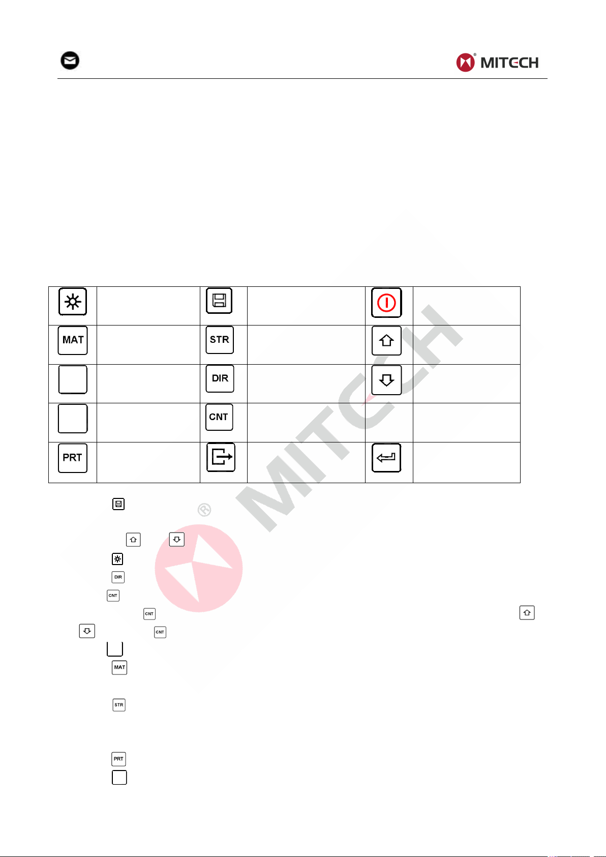
2.3 Keypad Definitions....................................................................................................................................8
2.4 Leeb Hardness Testing Principle............................................................................................................9
3 Preparation.............................................................................................................................................................9
3.1 Instrument Preparation and Inspection................................................................................................. 9
3.2 Impact Device Selection.......................................................................................................................... 9
3.3 Preparation of the Sample Surface........................................................................................................9
4 Testing Program................................................................................................................................................. 10
4.1 Start-Up.................................................................................................................................................... 10
4.3 Localization.............................................................................................................................................. 10
4.4 Testing.......................................................................................................................................................10
4.5 Read Measured Value............................................................................................................................11
4.6 Notification................................................................................................................................................11
5 Operation Detail.................................................................................................................................................. 11
5.1 Power On/Off........................................................................................................................................... 11
5.2 Material Setting....................................................................................................................................... 12
5.3 Hardness/Strength testing.....................................................................................................................12
5.4 Impact Direction Setting........................................................................................................................ 12
5.5 Average Times Setting...........................................................................................................................12
5.6 Data logging.............................................................................................................................................12
5.6.1 Viewing stored file/Group...................................................................................................................13
5.6.2 Deleting selected file/Group.............................................................................................................. 13
5.7 Print Function.......................................................................................................................................... 13
5.7.2Print the stored data.............................................................................................................................13
5.8 Date and Time Set..................................................................................................................................14
5.9 System Reset.......................................................................................................................................... 14
5.10 EL Backlight...........................................................................................................................................14
5.11 Auto Power Off...................................................................................................................................... 14
5.12 Paper Installation..................................................................................................................................14
5.13 Battery Charge......................................................................................................................................14
5.14 Battery Replacement........................................................................................................................... 15
5.15 Connecting to a Computer..................................................................................................................15
5.16 Error Code Reference..........................................................................................................................15
6 Maintenance & Servicing................................................................................................................................. 15
6.1 Impact Device Maintenance................................................................................................................. 15
6.2 Instrument Maintenance Program....................................................................................................... 15
6.3 Fault Analysis & Evacuation................................................................................................................. 16
6.4 Notice of Transport and Storage Conditions......................................................................................16
APPENDIX................................................................................................................................................................17
Table 1............................................................................................................................................................. 17
Table 2............................................................................................................................................................. 18

2
Table 3............................................................................................................................................................. 19
Table 4............................................................................................................................................................. 20
User Notes............................................................................................................................................................... 21

3
1 Overview
1.1 Advantages
Wide measuring range. Based on the principle of Leeb hardness testing theory. It can measure the
Leeb hardness of all metallic materials.
Large screen LCD, showing all functions and parameters. With EL background light.
Seven impact devices are available for special application. Automatically identify the type of impact
devices.
Test at any angle, even upside down.
Direct display of hardness scales HRB, HRC, HRA, HV, HB, HS, HL.
Large memory could store 100 groups (Relative to average times 32 ~1 ) information including
single measured value, mean value, impact direction, impact times, material and hardness scale
etc.
Battery information showing the rest capacity of the battery and the charge status.
User calibration function.
Software to connect to PC via USB port.
Thermal printer integrated, convenient for in field printing.
NI-MH rechargeable battery as the power source. Charge circuit integrated inside the instrument.
Continuous working period of no less than 150 hours (EL off and no printing).
Auto power off to save energy.
Outline dimensions:212mm×80mm×32mm
1.2 Main Application &Testing Range
1.2.1 Main Application
Die cavity of molds
Bearings and other parts
Failure analysis of pressure vessel, steam generator and other equipment
Heavy work piece
The installed machinery and permanently assembled parts
Testing surface of a small hollow space
Material identification in the warehouse of metallic materials
Rapid testing in large range and multi-measuring areas for large-scale work piece
1.2.2 Testing Range
Testing range refer to Table 1 and Table 2 in the Appendix.

4
1.3 Technical Specifications
Error and repeatability of displayed value see Table1-1 below.
Table 1-1
No.
Type of impact
device
Hardness value of Leeb
standard hardness block
Error of displayed
value
Repeatability
1
D
760±30HLD
530±40HLD
±6 HLD
±10 HLD
6 HLD
10 HLD
2
DC
760±30HLDC
530±40HLDC
±6 HLDC
±10 HLDC
6 HLD
10 HLD
3
DL
878±30HLDL
736±40HLDL
±12 HLDL
12 HLDL
4
D+15
766±30HLD+15
544±40HLD+15
±12 HLD+15
12 HLD+15
5
G
590±40HLG
500±40HLG
±12 HLG
12 HLG
6
E
725±30HLE
508±40HLE
±12 HLE
12 HLE
7
C
822±30HLC
590±40HLC
±12 HLC
12 HLC
Measuring range:HLD(170~960)HLD
Measuring direction:0°~360°
Hardness Scale:HL、HB、HRB、HRC、HRA、HV、HS
Display:segment LCD
Data memory:100 groups max.(relative to impact times 32~1)
Printing paper: width is (57.5±0.5)mm, diameter is 30mm.
Battery pack: 6V NI-MH
Battery charger: 9V/500mA
Continuous working period:about 150 hours(With backlight off, no printing)
Communication interface:USB1.1
1.4 Configuration
Table 1-2
No.
Item
Quantity
Remarks
Standard
Configuration
1
Main unit
1
2
D type impact device
1
With cable
3
Standard test block
1
4
Cleaning brush (I)
1
5
Small support ring
1
6
Battery Charger
1
9V 500mA
7
Paper for printing
1
8
Manual
1
9
Instrument package case
1
Optional
Configuration
11
Cleaning brush (II)
1
For use with G type
impact device
12
Other type of impact
devices and support rings
Refer to Table 3 and
Table 4 in the
appendix.
13
DataPro software
1
14
Communication cable
1
15
16

5
1.5 Working Conditions
Working temperature:-10℃~+50℃;
Storage temperature:-30℃~+60℃;
Relative humidity: ≤90%;
The surrounding environment should avoid of vibration, strong magnetic field, corrosive medium and
heavy dust.
1.6 Safety Instructions
The instrument can only work with the specially designed battery pack and power adapter (charger)
supplied by Mitech Co. LTD. Working with others may result in damage of the instrument, battery
leakage, fire or even explosion.
Do not cast the battery pack into fire and do not short circuit, disassemble or heat the battery pack,
otherwise battery leakage, fire or even explosion may occur.
Do not open the cover of the paper compartment or come into contact with the heating head of the
printer by hand or any part of your body to avoid burns due to high temperature when the printer is
printing.
2 Structure Feature &Testing Principle
2.1 Structure Feature
2.1.1 The Hardness Tester Appearance
1. Main unit
2. Impact device
CNT
MAT
PRT
DIR
STR
SCALE
FEED
MH310
Hardness Tester
2
M iT e c h
1

6
2.1.2 Parts of the Main body
1 Socket of impact device 2 Socket of USB 3 LOGO 4 Paper compartment cover 5 LCD display
6 Keypad 7 Battery switch 8 Power jack 9 Serial Number 10 Product label 11 Battery
compartment cover
MODEL: MH310 BATTERY: 6 V
HARDNESS TESTER
Material for Hardness Testing
9-Wrought Steel
8-Wrought Copper
7-Copper-Aluminum Alloys
6-Copper-Zinc Alloys
5-Cast Aluminum Alloys
4-Nodular Cast Iron
3-Gray Cast Iron
2-Stainless Steel
1-Cold Work Tool Steel
0-Steel and Cast Steel
CHARGER: 9V DC
CNT
MAT
PRT
DIR
STR
SCALE
FEED
MH310
Hardness Tester
M iT e c h
HL0108070811
OFF---ON
1
2
3
4
5
6
7
8
9
10
11

7
2.1.3 D Type Impact Device
1 2 3 4 5 6 7
1 Release button 2 Loading tube 3 Guide tube 4 Coil unit
5 Connection cable 6 Impact body 7 Support ring
2.1.4 Different Types of Impact Device
DC DL C D+15 E G
2.2 Main Screen
Below is the main display screen:
Hardness Scale
Average Icon
Direction
Battery Info
Impact Times
Measured Value
Memory Icon

8
Instruction of the Main Display Screen:
Material:The present presetting material.
Impact direction:The present impact direction.
Hardness scale:Hardness scale of the present measured value.
Battery information:Showing the rest capacity of the battery and the charging status.
Measured value:Display present single time measured value(without showing average icon),
or display the present mean value (with average icon prompting). “-HI-” means over conversion
value or measure range. “-LO-” means lower than conversion value or measure range.
Impact times:Times that have been impacted.
Average Icon:It will appear when showing the mean value of the measured values after reaching
the presetting impact times.
Memory Icon: It appears when operating the instrument memory.
2.3 Keypad Definitions
Table 2-1
Turn on/off the EL
backlight
Data Save or Data
Delete
Turn the instrument
on/off
Material Selection
Hardness/Strength
switch
Plus or Up
SCALE
Hardness Scale
Selection
Direction change
Minus or Down
FEED
Manual Paper
Feed
Impact Times set
Print data
Cancel or Exit
Data logging or
Enter
Press key to store present group of measured value into memory. This operation is only valid
after displaying the mean value.
Press key and could display single measured value.
Press key could switch on of off the background light of LCD.
Press key to set the impact direction.
Press key to change the impact times in one group. The impact times item will flash when first
pressing the key, and then the impact times value will plus or minus when pressing the or
key. Press key finally to exit from changing the impact times process.
Press
S
C
A
L
E
key to change the hardness scale.
Press key to change the material. Presetting hardness scale recovers to HL automatically after
material presetting changed.
Press key to switch between hardness test and strength test. Only D and DC type of impact
device has the function of strength testing. So hardness testing is the only selection if the impact
device is not D or DC type.
Press key to print out the measured values after measurement.
Press
F
E
E
D
key to manually feed the paper.

9
2.4 Leeb Hardness Testing Principle
The basic principle is to use an impact body of certain weight impacts against the testing surface under
certain test force, then measure the impacting velocity and the rebounding velocity of the impact body
respectively when the spherically test tip is located 1mm above the testing surface.
The calculation formula is as follows:
HL=1000×VB/ VA
Where, HL—— Leeb hardness value
VB—— Rebounding velocity of the impact body
VA—— Impacting velocity of the impact body
3 Preparation
3.1 Instrument Preparation and Inspection
Verification of the instrument is by using standard test block. The error and repeatability of displayed
value should be within the regulation of Appendix table 2. The instrument and impact device must be
calibrated using a standard hardness block before use as the first time, or having not been used for a
long time, or having reset the instrument system.
Press key, meanwhile pressing down the key to power on the system. Then the user calibration
screen shows as left below.
Test for 5 points on the standard hardness block.
It would display the average measured value
after measuring 5 times. Press key to
change to its nominal value.
Press key to confirm the calibration finally. Or
press the key to cancel the calibration.
Range of adjustment: ±30HL.
3.2 Impact Device Selection
Refer to Appendix Table 1 and Table 3 for selection of impact device.
3.3 Preparation of the Sample Surface
Preparation for sample surface should conform to the relative requirement in Appendix Table 3.
In the preparation processing for sample surface, the hardness effect of being heated or cold
processing on the surface of sample should be avoided.
Too big roughness of the being measured surface could cause error. So, the surface of the sample
to be measured must appear metallic luster, smoothing and polish, without oil stain.
Support of test sample. Support is no necessary for heavy sample. Medium-weight parts must be
set on the smoothing and stable plane. The sample must set absolutely equability and without any
wobble.
Curved surface: The best testing surface of sample is flat. When the curvature radius R of the
surface to be tested is smaller than 30mm (D, DC, D+15,C, E and DL type of impact device) and
smaller than 50mm (G type of impact device), the small support ring or the shaped support rings
should be chosen.
The sample should have enough thickness, minimum thickness of sample should conform to Table
3.
For the sample with hardened layer on surface, the depth of hardened layer should conform to Table
3.

10
Coupling. Light-weight sample must be firmly coupled with a heavy base plate. Both coupled
surface must be flat and smooth, and there is no redundant coupling agent existing. The impact
direction must be vertical to the coupled surface. When the sample is a big plate, long rod or
bending piece, it can be deformed and become unstable, even though its weight and thickness is
big enough, and accordingly, the test value may not be accurate. So the sample should be
reinforced or supported at its back.
Magnetism of the sample itself should be avoided.
4 Testing Program
Note :Use a calibrated hardness tester, test the standard test block downward vertically for 5
times, the arithmetical average value compare with the value of standard test block. If this value
exceeds the standard value, could use the function of user calibration to adjust.
4.1 Start-Up
Insert the plug of the impact device into the socket of impact device on the instrument.
Press the key,now power is on. The instrument is in working mode.
Pushing the loading-tube downwards until contact is felt. Then allow it to slowly return to the starting
position or using other method locking the impact body.
4.3 Localization
Press the impact device supporting ring firmly on the surface of the sample, the impact direction
should be vertical to the testing surface.
4.4 Testing
Press the release button on the upside of the impact device to test. The sample and the impact
device as well as the operator are all required to be stable now. The action direction should pass the
axis of the impact device.
Each measure area of the sample usually need 3 to 5 times of testing operation. The result data
dispersion should not more than mean value±15HL.
The distance between any two impact points or from the center of any impact point to the edge of
testing sample should conform to the regulation of Table 4-1.
If want accurate conversion from the Leeb hardness value to other hardness value, contrastive test
is needed to get conversion relations for the special material. Use inspection qualified Leeb
hardness tester and corresponding hardness tester to test at the same sample respectively. For
each hardness value, each measure homogeneously 5 points of Leeb hardness value in the
surrounding of more than three indentations which need conversion hardness, using Leeb hardness
arithmetic average value and corresponding hardness average value as correlative value
respectively, make individual hardness contrastive curve. Contrastive curve at least should include
three group of correlative data.

11
Table 4-1
Type of Impact
Device
Distance of center of the two
indentations
Distance of center of the
indentation to sample edge
Not less than (mm)
Not less than (mm)
D、DC
3
5
DL
3
5
D+15
3
5
G
4
8
E
3
5
C
2
4
4.5 Read Measured Value
After each impact operation, the LCD will display the current measured value, impact times plus one, the
buzzer would alert a long howl if the measured value is not within the valid range. When reaching the
presetting impact times, the buzzer will alert a long howl. After 2 seconds, the buzzer will alert a short
howl, and display the mean measured value.
NOTE:HL values tested by different impact devices are different,eg.780HLD≠780HLC
4.6 Notification
Replacing the impact device must be done during Power off. Otherwise the main body could not
identify the type of the impact device, and it may damage the circuit board of the main body.
You could not save the current test value if the impact time is less than the presetting times value.
Only type D and type DC of impact device have the function of strength test option. You can not
change the setting to strength testing when using other types of impact device. The setting would be
set to hardness testing automatically after replacing the impact device whether the setting is
hardness testing or not before.
Not all materials could convert to all hardness scale value. The hardness scale is reset to HL
automatically after changing the material. So select material firstly before changing the hardness
scale.
5 Operation Detail
5.1 Power On/Off
Press to power on the instrument. Be sure to plug in the impact device before powering on. The
system would automatically detect the type of the impact device during power up, and would display this
information on the screen. Users should pay attention to the probe type displayed on the screen. After
pausing for several second, the screen will exit and enter the main display screen as following:
The instrument can be turned off by pressing the key while it is working. The tool has a special
memory that retains all of its settings even when the power is off.
Note: If the instrument is in power off condition, it will turns on automatically after the charge
power is connected.

12
5.2 Material Setting
Press key to change the material to the one you want to preset. Hardness scale recovers to HL
automatically after material presetting changed. Please select material firstly, then select hardness
scale.
In hardness testing, you can select the material among the following materials: Steel and Cast Steel、
Cold Work Tool Steel、Stainless Steel、Gray Cast Iron、Nodular Cast Iron、Cast Aluminum Alloys、
Copper-Zinc Alloys 、Copper-Aluminum Alloys 、Wrought Copper and Wrought Steel. The relationship
between the material number displayed on the instrument screen and the material is as follows:
Table 5-1
Material No.
Material
Material No.
Material
0
Steel and cast steel
5
Cast aluminum alloys
1
Cold work tool steel
6
Copper-Zinc alloys
2
Stainless steel
7
Copper –Aluminum alloys
3
Gray cast iron
8
Wrought copper
4
Nodular cast iron
9
Wrought steel
In strength testing, the following materials are selectable: Mild Steel、High-Carbon Steel、Cr Steel、Cr-V
Steel、Cr-Ni Steel、Cr-Mo Steel、Cr-Ni-Mo Steel、Cr-Mn-Si Steel、Super Strength Steel and Stainless
Steel. The relationship between the material number displayed on the instrument screen and the
material is as follows:
Table 5-2
Material No
Material
Material No
Material
0
Mild steel
5
Cr-Mo steel
1
High carbon steel
6
Cr-Ni-Mo steel
2
Cr steel
7
Cr-Mn-Si steel
3
Cr-V steel
8
Super strength steel
4
Cr-Ni steel
9
Stainless steel
NOTE”
1.The hardness scale will return to HL after changing the material setting.
2.Please choose the material before choosing hardness scale.
5.3 Hardness/Strength testing
Press key to switch between hardness testing and strength testing (бb) .
Note: Only D and DC type of impact device has the function of strength testing. So hardness
testing is the only selection if the impact device is not D or DC type.
In hardness testing, Press
S
C
A
L
E
key to change the hardness scale. The supported hardness scale
includes: HL, HV, HB, HRC, HS, HRB and HRA.
Note:
Here only displays the valid hardness scale for the present selected impact device and
material. It would not display the hardness scale which is not valid.
Please select material firstly, then select hardness scale.
Presetting hardness scale recovers to HL automatically after presetting material is changed.
5.4 Impact Direction Setting
Press the key to move to the impact direction that you will preset.
5.5 Average Times Setting
You could modify average times within the range of 1 to 32 as following:
1) Press key in testing state. The impact times item will begin to flash.
2) Press or key to set the average times to the number you want.
3) Press key finally to exit from the operation.
5.6 Data logging
At most one hundred files (F00-F99, one group as one file) can be stored inside the gauge. By simply

13
pressing the key after a new measurement finishes-the screen showing the “AVE” icon, the
measured hardness/strength group values will be saved to memory. The new saved file is appended as
the last file of the memory. This function provides the user with the ability to view/delete a file/group
previously saved in memory.
5.6.1 Viewing stored file/Group
To view the memory data, follow the steps:
1) Press the key to activate the data logging function. The memory icon will appear. It will display
the current file name, the test parameter of the group data and the mean value of the group. If there
is no data in the memory, it will display: <E04>, which means no memory data, and then return back.
2) Use the key and the key to select the desired file to view.
3) Press the key to see details of that group data.
4) Use the key and the key to view each single measured data in that group while viewing
details.
5) Press the key to return to previous screen at any time during data logging.
5.6.2 Deleting selected file/Group
The user may require deleting a file from the instrument memory. The procedure is outlined in the
following steps.
1) Press the key to activate the data logging function. The memory icon will appear. It will display
the current file name, the test parameter of the group data and the mean value of the group. If there
is no data in the memory, it will display: <E04>, which means no memory data, and then return back.
2) Use the key and the key to scroll to the file that will be deleted.Press the key on the
desired file. It will automatically delete the file, and display “-DEL”.After you delete,the data number
will list again which needs about 30 seconds,don’t turn off the machine to avoid data error.
3) Press the key to exit the data logging function or press to selected data group for details
4) Use the key and the key for single test in data groups.
5) Press to return step 3and return to measurement mode.
5.7 Print Function
At the end of the inspection process, or end of the day, the user may require the readings be printed. You
can print out the measurement result immediately after each testing process, by easily pressing the
key.
5.7.2Print the stored data
If you want to print the data stored in the instrument memory, then following is the steps:
1. Power on the machine
2. Press the key to activate the data logging function. The memory icon will appear.
3. Use the key and the key to select the desired file.
4. Press the key to print the selected file. This operation will print out all the data in current file.
5. Press the key to exit the data logging functions and return to measurement mode.
6. Press the key to stop printing after current printing during the printing period.
5.7.3 Manually feeding paper
When the printer is powered on and ready for printing, press
F
E
E
D
key then the instrument will start
manual paper feeding. Press and keep holding the
F
E
E
D
key to start paper feeding, while releasing the
key to stop paper feeding.
Note:
Printing function is unavailable while charging.
Printing can be stopped by pressing the key.
Do not open the cover of the paper compartment during printing. Otherwise the
instrument may not print normally.
Over high ambient humidity (above 85% of relative humidity) or over low ambient
humidity (below 20% of relative humidity) may reduce the print quality.

14
Printing with paper that has been stored for over long period of time or of poor quality
may reduce the print quality or even damage the printer.
5.8 Date and Time Set
Press down the key while powering on the instrument to set the instrument date and time. The year
item shown as “XXXX” will firstly prompt out. Use the key and the key to change to current year.
Confirm the change by pressing and step to next item. In the following, the Month, Date, Hour and
Minute item will prompt out in turn.You can cancel all the changes by pressing and exit from the
date and time setting at any time during the operation.
5.9 System Reset
Press down the
S
C
A
L
E
key while powering on the instrument will restore factory defaults. The only time
this might possibly helpful is if the parameter in the instrument was somehow corrupted.
5.10 EL Backlight
With the EL background light, it is convenient to work in the dark condition. Press key to switch on or
switch off the background light at any moment as you need after power on. Since the EL light will
consume much power, turn on it only when necessary.
5.11 Auto Power Off
The instrument features an auto power off function designed to conserve battery life. If the tool is idle
(neither measuring nor any key operation) for 5 minutes, it will turn itself off. Before powering off, the
LCD display of the instrument will continue flashing for 20 seconds. Except key , press any key could
stop the twinkle of LCD screen and stop the operation of power off at the moment.
While the voltage of the battery is too low, the display will show <E00>, then power off
automatically.
When the instrument is being charged, the Auto Power Off will not function.
5.12 Paper Installation
Hold Both ends of the paper compartment
with fingers and open the compartment
cover with moderate strength.
According to the illustration, put the paper
into the paper compartment with attention to
the paper direction. If the paper is misplaced,
the instrument will fail to print.
Pull a trip of paper out of the compartment.
Make sure that the paper is well in place and
close the paper compartment cover.
5.13 Battery Charge
The instrument uses a NI-MH battery pack as its power source. When the battery pack almost runs out,
the battery symbol on the display will glint . It needs charging as soon as possible. Try to drain
your battery pack as fully as possible before it is charged for longest battery service.
The battery switch should be at ‘ON’ condition before charging.
Plug the power adapter into the mains supply power socket and then plug the charger connector
into the power jack of the instrument. If the instrument is in power off condition, it will turns on
automatically after the charger plug is inserted into the power jack. The battery symbol will

15
alternately shows between and when charging. The more of the dark part indicates
the more close to full capacity.
When the battery is fully charged, the battery symbol on the display will glint .
Please use the configured AC-DC adapter to charge the battery pack.
5.14 Battery Replacement
When the battery pack fails to be charged, the user should replace the batteries following the program
below:
Power down the instrument.
Take off the battery compartment cover and take out the battery pack.
Insert the connection plug of the new battery pack into the socket on the circuit board.
Reset the battery cover.
Turn on the instrument to check.
Warning: Please pay much attention to the polarity of the battery during battery replacement.
5.15 Connecting to a Computer
Insert one connection plug of the transmission cable into the USB socket on the right side of main body,
and insert the another plug into the USB port on the back of computer box. Refer to the manual of the
DataPro software for detailed information.
5.16 Error Code Reference
Error Code
Explanation
Error Code
Explanation
E00
Battery exhausted
E05
Can not print
E01
Value out of range
E06
Battery Charging
E02
Measurement not finished
E07
No paper for printing
E03
Data already saved
E08
Over Temperature
E04
No memory data
E09
6 Maintenance & Servicing
6.1 Impact Device Maintenance
After the impact device has been used for 1000--2000 times, please use the nylon brush provided to
clean the guide tube and impact body. When cleaning the guide tube, unscrew the support ring first,
then take out the impact body, spiral the nylon brush in counter-clock direction into the bottom of
guide tube and take it out for 5 times, and then install the impact body and support ring again.
Release the impact body after use.
Any lubricant is absolutely prohibited inside the impact device.
6.2 Instrument Maintenance Program
When using standard Rockwell hardness block to testing, if all the error is bigger than 2 HRC, it may
be the invalidation of impacted ball top caused by abrasion. Changing the spherical test tip or
impact object should be considered.
When the hardness tester appears some other abnormal phenomena, please do not dismantle or
adjust any fixedly assembled parts. Fill in and present the warranty card to us. The warranty service
can be carried on.

16
6.3 Fault Analysis & Evacuation
Fault Appearance
Fault Analysis
Handling method
Charge failure
Battery failure
Replace the battery with a new pack
The battery is switched off
Switch on the battery
No measured value
Impact device cable failure
Replace the cable
Failure power on
Battery exhaustion
Charge the battery
The battery is switched off
Switch on the battery
6.4 Notice of Transport and Storage Conditions
Keep it away from vibration, strong magnetic field, corrosive medium, dumpiness and dust. Storage
in ordinary temperature.
With original packing, transport is allowed on the third grade highway.

17
APPENDIX
Table 1
Material
Method
Impact device
D/DC
D+15
C
G
E
DL
Steel and cast
steel
HRC
20~68.5
19.3~
67.9
20.0~
69.5
22.4~70.7
20.6~
68.2
HRB
38.4~
99.6
47.7~
99.9
37.0~
99.9
HRA
59.1~
85.8
61.7~88.0
HB
127~
651
80~638
80~683
90~646
83~663
81~646
HV
83~976
80~937
80~996
84~1042
80~950
HS
32.2~
99.5
33.3~
99.3
31.8~
102.1
35.8~
102.6
30.6~
96.8
Cold work
tool steel
HRC
20.4~
67.1
19.8~
68.2
20.7~
68.2
22.6~70.2
HV
80~898
80~935
100~
941
82~1009
Stainless steel
HRB
46.5~
101.7
HB
85~655
HV
85~802
Grey cast iron
HRC
HB
93~334
92~326
HV
Nodular cast iron
HRC
HB
131~
387
127~364
HV
Cast aluminum
alloys
HB
19~164
23~210
32~168
HRB
23.8~
84.6
22.7~
85.0
23.8~
85.5
BRASS(copper-z
inc alloys)
HB
40~173
HRB
13.5~
95.3
BRONZE(copper
-aluminum/tin
alloys)
HB
60~290
Wrought copper
alloys
HB
45~315

18
Table 2
No.
Material
HLD
Strength σb(MPa)
1
Mild steel
350~522
374~780
2
High-Carbon steel
500~710
737~1670
3
Cr steel
500~730
707~1829
4
Cr-V steel
500~750
704~1980
5
Cr-Ni steel
500~750
763~2007
6
Cr-Mo steel
500~738
721~1875
7
Cr-Ni-Mo steel
540~738
844~1933
8
Cr-Mn-Si steel
500~750
755~1993
9
Super strength steel
630~800
1180~2652
10
Stainless steel
500~710
703~1676

19
Table 3
Type of impact device
DC(D)/DL
D+15
C
G
E
Impacting energy
Mass of impact body
11mJ
5.5g/7.2g
11mJ
7.8g
2.7mJ
3.0g
90mJ
20.0g
11mJ
5.5g
Test tip hardness:
Dia. Test tip:
Material of test tip:
1600HV
3mm
Tungsten
carbide
1600HV
3mm
Tungsten
carbide
1600HV
3mm
Tungsten
carbide
1600HV
5mm
Tungsten
carbide
5000HV
3mm
synthetic
diamond
Impact device diameter:
Impact device length:
Impact device weight:
20mm
86(147)/
75mm 50g
20mm
162mm
80g
20mm
141mm
75g
30mm
254mm
250g
20mm
155mm
80g
Max. hardness of sample
940HV
940HV
1000HV
650HB
1200HV
Mean roughness value of
sample surface Ra:
1.6μm
1.6μm
0.4μm
6.3μm
1.6μm
Min. weight of sample:
Measure directly
Need support firmly
Need coupling tightly
>5kg
2~5kg
0.05~2kg
>5kg
2~5kg
0.05~2kg
>1.5kg
0.5~1.5kg
0.02~0.5kg
>15kg
5~15kg
0.5~5kg
>5kg
2~5kg
0.05~2kg
Min. thickness of sample
Coupling tightly
Min. layer thickness for
surface hardening
5mm
≥0.8mm
5mm
≥0.8mm
1mm
≥0.2mm
10mm
≥1.2mm
5mm
≥0.8mm
Size of tip indentation
Hardness
300HV
Indentation
diameter
Depth of
indentation
0.54mm
24μm
0.54mm
24μm
0.38mm
12μm
1.03mm
53μm
0.54mm
24μm
Hardness
600HV
Indentation
diameter
Depth of
indentation
0.54mm
17μm
0.54mm
17μm
0.32mm
8μm
0.90mm
41μm
0.54mm
17μm
Hardness
800HV
Indentation
diameter
Depth of
indentation
0.35mm
10μm
0.35mm
10μm
0.35mm
7μm
--
--
0.35mm
10μm
Available type of impact
device
DC: Test hole
or hollow
cylindrical;
DL:Testslender
narrow groove
or hole
D+15: Test
groove
or
reentran
t surface
C: Test
small,light,thi
n parts and
surface of
hardened
layer
G: Test
large,
thick,heavy
and rough
surface steel
E: Test super
high
hardness
material
Table of contents
Other MITECH Test Equipment manuals