MITECH MH320 User manual

1
mvip@mitech-ndt.com
CONTENTS
1 Overview................................................................................................................................................................. 3
1.1 Advantages...................................................................................................................................................3
1.2 Main Application &Testing Range.............................................................................................................3
1.2.1 Main Application....................................................................................................................................... 3
1.2.2 Testing Range...........................................................................................................................................3
1.3 Configuration................................................................................................................................................4
1.4 Working Conditions.....................................................................................................................................4
1.5 Safety Instructions.......................................................................................................................................4
2 Structure Feature &Testing Principle............................................................................................................. 5
2.1 Structure Feature........................................................................................................................................ 5
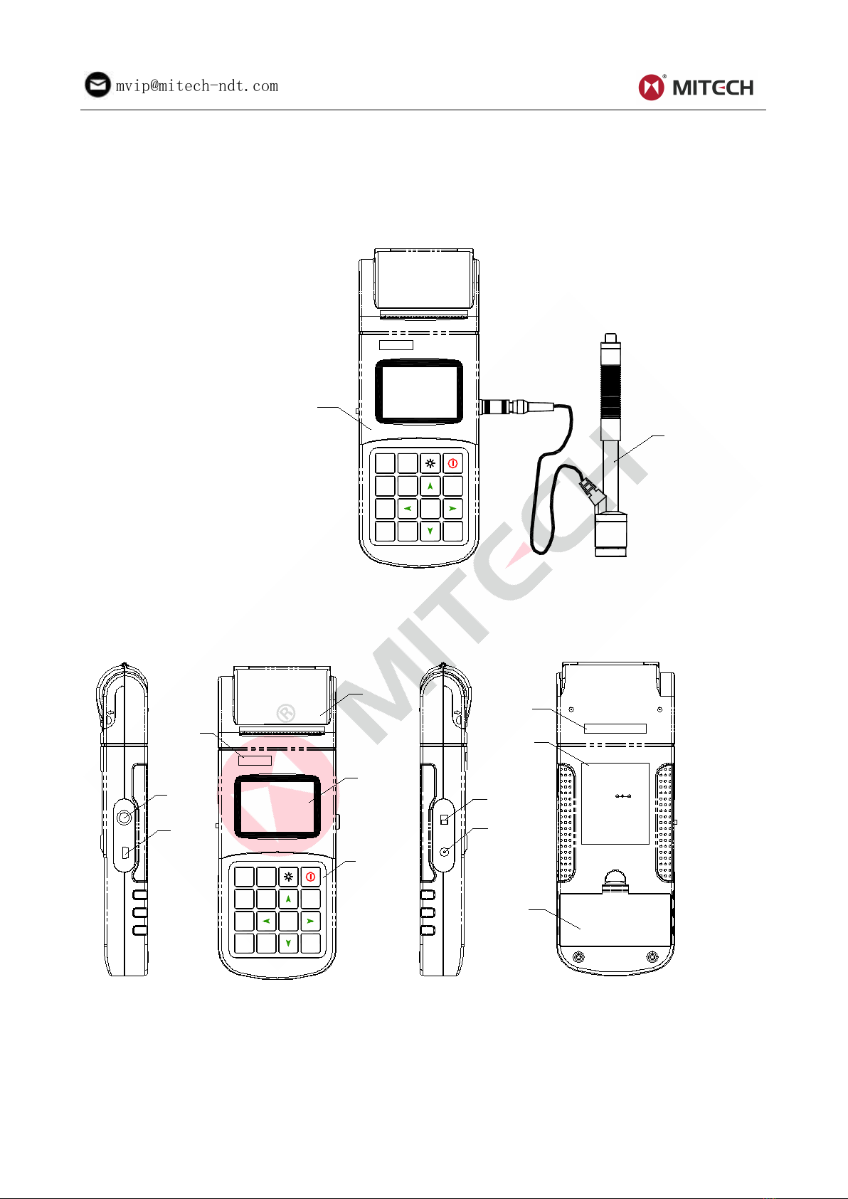
2.1.1 The Hardness Tester Appearance........................................................................................................ 5
2.1.2 Parts of the Main body............................................................................................................................ 5
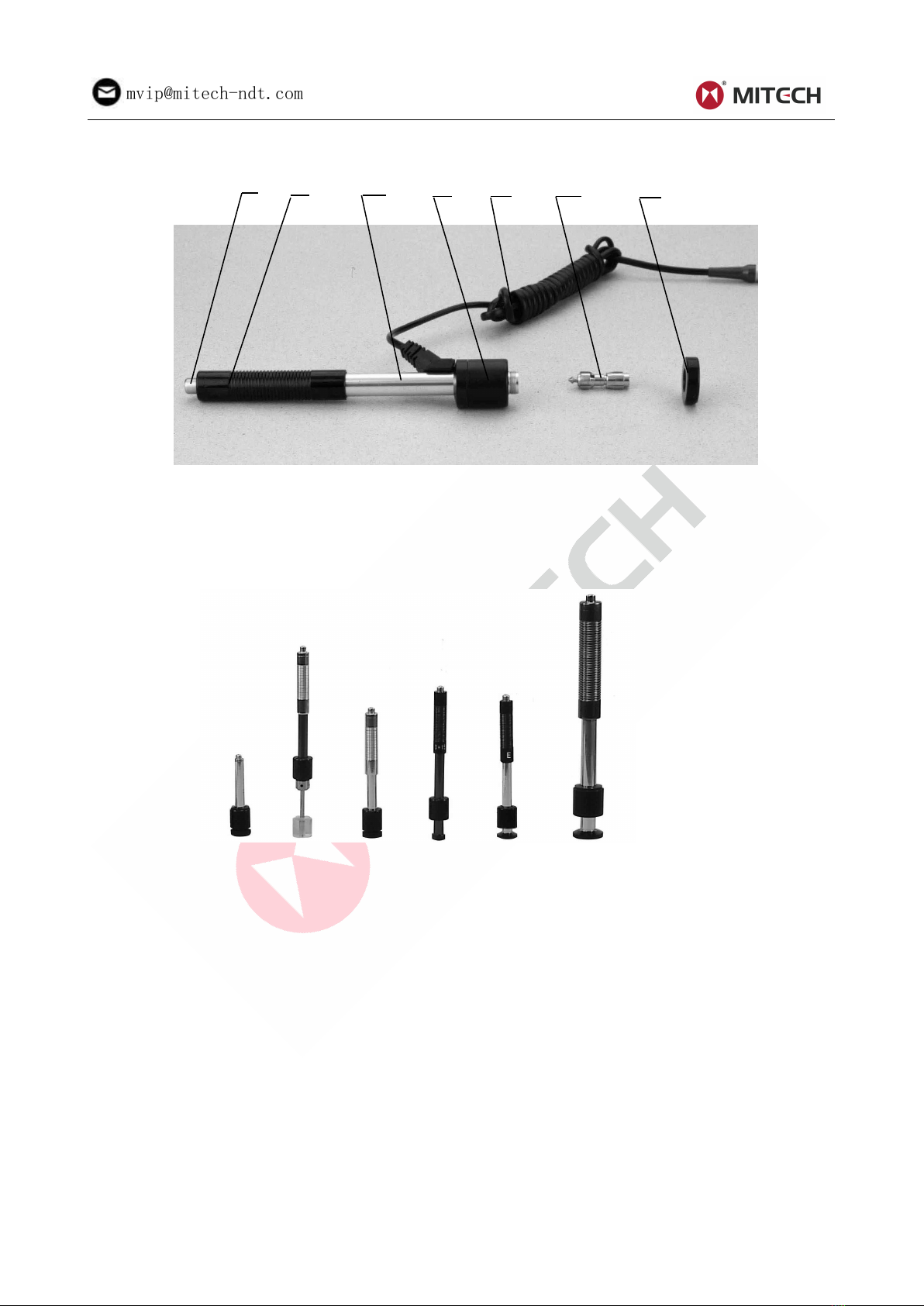
2.1.3 D Type Impact Device............................................................................................................................. 6
2.1.4 Different Types of Impact Device.......................................................................................................... 6
2.2 Leeb Hardness Testing Principle..............................................................................................................6
3 Technical Specifications.................................................................................................................................... 6
4 Preparation & Testing..........................................................................................................................................8
4.1 Preparation & Inspection before Testing................................................................................................. 8
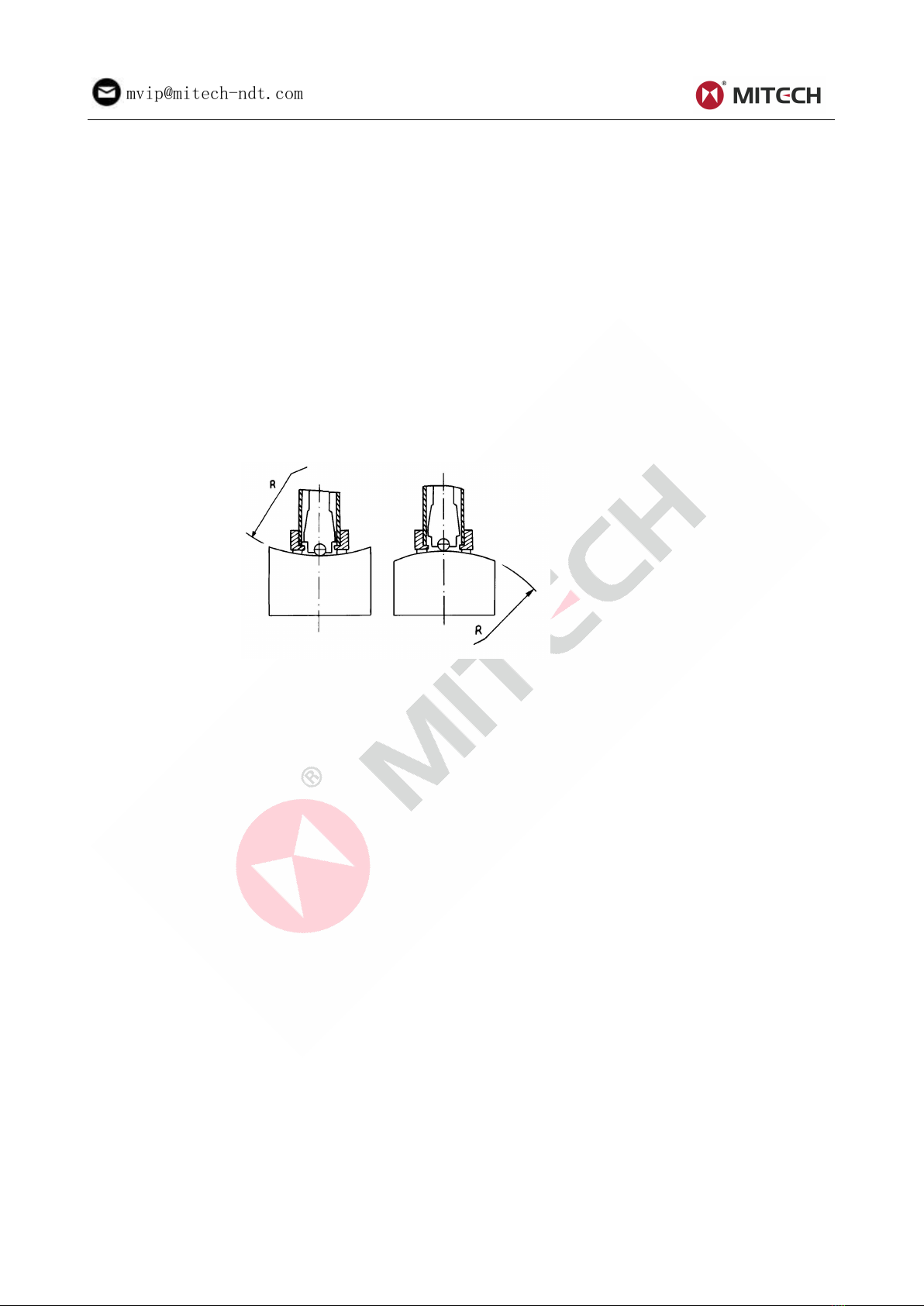
4.1.1Preparation of Sample Surface.............................................................................................................. 8
4.1.2 System Setting......................................................................................................................................... 8
4.1.3Presetting Testing condition.................................................................................................................... 8
4.2 Testing Program.......................................................................................................................................... 8
4.2.1 Start-Up..................................................................................................................................................... 8
4.2.2 Loading...................................................................................................................................................... 9
4.2.3 Localization............................................................................................................................................... 9
4.2.4 Testing........................................................................................................................................................9
4.2.5 Read measured value.............................................................................................................................9
4.2.6 Power Off................................................................................................................................................ 10
5 Advice....................................................................................................................................................................10
6 Operation in Details...........................................................................................................................................10
6.1 Power On....................................................................................................................................................10
6.2 Power Off....................................................................................................................................................10
6.3 Testing.........................................................................................................................................................10
6.3.1 Instruction of the Main Display Interface............................................................................................11
6.3.2 Testing Operation at the Main Display Interface...............................................................................11
6.3.3 Key Operation at the Main Display Interface.................................................................................... 11
6.4 Menu Structure.......................................................................................................................................... 11
6.5 Test Set....................................................................................................................................................... 13
6.6 Print Function.............................................................................................................................................15
6.7.Memory Manager......................................................................................................................................15
6.8 Browsing Memory Data Groups............................................................................................................. 17
6.9 System Set.................................................................................................................................................18
6.10 Software Information.............................................................................................................................. 19
6.11 System Calibration..................................................................................................................................19
6.12 EL Background Light..............................................................................................................................20
6.13 Auto Power Off........................................................................................................................................ 20
6.14 Paper Loading......................................................................................................................................... 20
6.15 Battery Charge........................................................................................................................................ 20
6.16 Battery Replacement..............................................................................................................................21
6.17 Connection of Data Transmission Cable............................................................................................ 21
7 Fault Analysis & Evacuation........................................................................................................................... 21
8 Servicing & Maintenance................................................................................................................................. 21
8.1 Impact Device Servicing.......................................................................................................................... 21
8.2 Normal Maintenance Program................................................................................................................21
9 Calibration............................................................................................................................................................21
10 Notice of Transport and Storage Conditions........................................................................................... 21

2
mvip@mitech-ndt.com
APPENDIX................................................................................................................................................................22
Table 1............................................................................................................................................................... 22
Table 2............................................................................................................................................................. 23
Table 3............................................................................................................................................................. 24
Table 4............................................................................................................................................................. 25
User Notes............................................................................................................................................................... 26
ponpe.com

3
mvip@mitech-ndt.com
1Overview
1.1 Advantages
Wide measuring range. Based on the principle of Leeb hardness testing theory. It can measure the
Leeb hardness of all metallic materials.
Large screen(128×64 dot matrix LCD), showing all functions and parameters.
Test at any angle, even upside down.
Direct display of hardness scales HRB, HRC, HRA, HV, HB, HS, HL.
Seven impact devices are available for special application. Automatically identify the type of impact
devices.
Large capacity memory could store 500 groups (Relative to average times32 ~1 ) information
including single measured value, mean value, testing date, impact direction, impact times, material
and hardness scale etc.
Upper and lower limit can be preset. It will alarm automatically when the result value exceeding the
limit.
Battery information indicates the rest capacity of the battery and the charge status.
User calibration function.
Software to connect with PC via USB port.
With EL background light.
Thermal printer integrated, convenient for in field printing.
NI-MH rechargeable battery as the power source. Charge circuit integrated inside the instrument.
Continuous working period of no less than 150 hours (EL off and no printing).
Auto power off to save energy.
Outline dimensions:212mm×80mm×32mm
1.2 Main Application &Testing Range
1.2.1 Main Application
Die cavity of molds
Bearings and other parts
Failure analysis of pressure vessel, steam generator and other equipment
Heavy work piece
The installed machinery and permanently assembled parts
Testing surface of a small hollow space
Material identification in the warehouse of metallic materials
Rapid testing in large range and multi-measuring areas for large-scale work piece
1.2.2 Testing Range
Testing range refer to Table 1 and Table 2 in the Appendix.

4
mvip@mitech-ndt.com
1.3 Configuration
Table 1-1
No.
Item
Quantity
Remarks
Standard
Configuration
1
Main Unit
1
2
D type impact device
1
With cable
3
Standard test block
1
4
Cleaning brush (I)
1
5
Small support ring
1
6
Battery Charger
1
9V 500mA
7
Paper for printing
1
8
Manual
1
9
Instrument case
1
Optional
Configuration
11
Cleaning brush (II)
1
For use with G type
impact device
12
Other type of impact
devices and support rings
Refer to Table 3 and
Table 4 in the
appendix.
13
Data-Pro software
1
14
Communication cable
1
15
16
1.4 Working Conditions
Working temperature:-10℃~+50℃;
Storage temperature:-30℃~+60℃;
Relative humidity: ≤90%;
The surrounding environment should avoid of vibration, strong magnetic field, corrosive medium
and heavy dust.
1.5 Safety Instructions
The instrument can only work with the specially designed battery pack and power adapter (charger)
supplied by Mitech Co. LTD. Working with others may result in damage of the instrument, battery
leakage, fire or even explosion.
Do not cast the battery pack into fire and do not short circuit, disassemble or heat the battery pack,
otherwise battery leakage, fire or even explosion may occur.
Do not open the cover of the paper compartment or come into contact with the heating head of the
printer by hand or any part of your body to avoid burns due to high temperature when the printer is
printing.
ponpe.com

5
mvip@mitech-ndt.com
2 Structure Feature &Testing Principle
2.1 Structure Feature
2.1.1 The Hardness Tester Appearance
1. Main unit
2. Impact device
2.1.2 Parts of the Main body
1 Socket of impact device 2 Socket of USB 3 LOGO 4 Paper compartment cover 5 LCD display
6 Keypad 7 Battery switch 8 Power jack 9 Serial Number 10 Product label 11 Battery
compartment cover
DEL SAVE
ESC
MENU
ENTER
MAT
DIR
FEED
PRT
1
M iT e c h
2
MODEL: MH320
BATTERY: 6V NI-MH
HARDNESS TESTER
CAUTION:
1 Do not disassemble
3 Use only supplied AC-DC adapter
for charging
CHARGER: 9V DC
2 Do not dispose of in fire or water
SCALE
DEL SAVE
ESC
MENU
ENTER
MAT
DIR
FEED
PRT
11
10
9
8
7
6
5
4
3
2
1
OFF---ON
HL0108070811
M iT e c h
ponpe.com

6
mvip@mitech-ndt.com
2.1.3 D Type Impact Device
1 2 3 4 5 6 7
1 Release button 2 Loading tube 3 Guide tube 4 Coil unit
5 Connection cable 6 Impact body 7 Support ring
2.1.4 Different Types of Impact Device
DC DL C D+15 E G
2.2 Leeb Hardness Testing Principle
The basic principle is: use an impact body of certain weight impacts against the testing surface under
certain test force, then measure the impacting velocity and the rebounding velocity of the impact body
respectively when the spherically test tip is located 1mm above the testing surface.
The calculation formula is as follows:
HL=1000×VB/ VA
Where, HL—— Leeb hardness value
VB—— Rebounding velocity of the impact body
VA—— Impacting velocity of the impact body
3 Technical Specifications
Error and repeatability of displayed value see Table 3-1.
ponpe.com

7
mvip@mitech-ndt.com
Table 3-1
No.
Type of impact
device
Hardness value of Leeb
standard hardness block
Error of displayed
value
Repeatability
1
D
760±30HLD
530±40HLD
±6 HLD
±10 HLD
6 HLD
10 HLD
2
DC
760±30HLDC
530±40HLDC
±6 HLDC
±10 HLDC
6 HLD
10 HLD
3
DL
878±30HLDL
736±40HLDL
±12 HLDL
12 HLDL
4
D+15
766±30HLD+15
544±40HLD+15
±12 HLD+15
12 HLD+15
5
G
590±40HLG
500±40HLG
±12 HLG
12 HLG
6
E
725±30HLE
508±40HLE
±12 HLE
12 HLE
7
C
822±30HLC
590±40HLC
±12 HLC
12 HLC
Measuring range:HLD(170~960)HLD
Measuring direction:360°
Hardness Scale:HL、HB、HRB、HRC、HRA、HV、HS
Display:dot matrix LCD,128×64 dots
Data memory:500 groups max.(relative to impact times 32~1)
Printing paper: width is (57.5±0.5)mm, diameter is 30mm
Battery pack: 6V NI-MH
Battery charger: 9V/500mA
Continuous working period:about 150 hours(With backlight off, no printing)
Communication interface:USB1.1

8
mvip@mitech-ndt.com
4 Preparation & Testing
4.1 Preparation & Inspection before Testing
4.1.1Preparation of Sample Surface
Preparation for sample surface should conform to the relative requirement in the Appendix Table 3.
In the preparation processing for sample surface, the hardness effect of being heated or cold
processing on the surface of sample should be avoided.
Too big roughness of the being measured surface could cause measure error. So, the surface of the
sample to be measured must appear metallic luster, smoothing and polish, without oil stain.
Support of test sample. Support is no necessary for heavy sample. Medium-weight parts must be
set on the smoothing and stable plane. The sample must set absolutely equability and without any
wobble.
Curved surface: The best testing surface of sample is flat. When the curvature radius R of the
surface to be tested is smaller than 30mm (D, DC, D+15,C, E and DL type of impact device) and
smaller than 50mm (G type of impact device), the small support ring or the shaped support rings
should be chosen.
The sample should have enough thickness, minimum thickness of sample should conform to Table
3.
For the sample with hardened layer on surface, the depth of hardened layer should conform to Table
3.
Coupling. Light-weight sample must be firmly coupled with a heavy base plate. Both coupled
surface must be flat and smooth, and there is no redundant coupling agent existing. The impact
direction must be vertical to the coupled surface. When the sample is a big plate, long rod or
bending piece, it can be deformed and become unstable, even though its weight and thickness is
big enough, and accordingly, the test value may not be accurate. So the sample should be
reinforced or supported at its back.
Magnetism of the sample itself should be avoided.
4.1.2 System Setting
See 6.9 for details.
4.1.3Presetting Testing condition
See 6.5 for details.
4.2 Testing Program
Verification of the tester is by using standard test block. The error and repeatability of displayed value
should be within the regulation of Appendix table 2.
Note :Use a calibrated hardness tester, test the standard test block downward vertically for 5
times, the arithmetical average value compare with the value of standard test block. If this value
exceeds the standard value, could use the function of software calibration to adjusting.
4.2.1 Start-Up
Insert the plug of the impact device into the socket of impact device on the tester.
ponpe.com

9
mvip@mitech-ndt.com
Press【 】key,now power is connected. The instrument is in testing condition.
4.2.2 Loading
Pushing the loading-tube downwards until contact is felt. Then allow it to slowly return to the starting
position or using other method locking the impact body.
4.2.3 Localization
Press the impact device supporting ring on the surface of the sample firmly, the impact direction should
be vertical to the testing surface.
4.2.4 Testing
Press the release button on the upside of the impact device to test. The sample and the impact
device as well as the operator are all required to be stable now. The action direction should pass the
axis of the impact device.
Each measure area of the sample usually need 5 times of testing operation. The result data
dispersion should not more than mean value±15HL.
The distance between any two impact points or from the center of any impact point to the edge of
testing sample should conform to the regulation of Table 4-1.
If want accurate conversion from the Leeb hardness value to other hardness value, contrastive test
is needed to get conversion relations for the special material. Use inspection qualified Leeb
hardness tester and corresponding hardness tester to test at the same sample respectively. For
each hardness value, each measure homogeneously 5 points of Leeb hardness value in the
surrounding of more than three indentations which need conversion hardness, using Leeb hardness
arithmetic average value and corresponding hardness average value as correlative value
respectively, make individual hardness contrastive curve. Contrastive curve at least should include
three group of correlative data.
Table 4-1
Type of Impact
Device
Distance of center of the two
indentations
Distance of center of the
indentation to sample edge
Not less than (mm)
Not less than (mm)
D、DC
3
5
DL
3
5
D+15
3
5
G
4
8
E
3
5
C
2
4
4.2.5 Read measured value
After each impact operation, the LCD will display the current measured value, impact times plus one, the
buzzer would alert a long howl if the measured value is not within the valid range. When reaching the
presetting impact times, the buzzer will alert a long howl. After 2 seconds, the buzzer will alert a short

10
mvip@mitech-ndt.com
howl, and display the mean measured value.
NOTE:HL values tested by different impact devices are different,eg.780HLD≠780HLC
4.2.6 Power Off
Press【 】key to turn off the instrument.
5 Advice
Replacing the impact device must be done during Power off. Otherwise the main body can not
identify the type of the impact device, and it can damage the circuit board of the main body.
You could not save the current test value if the test times are less than the presetting times value.
Only type D and type DC of impact device have the function of strength measure option. You can
not modify the 【Set hardness or бb】setting when using other types of impact device. The 【Set
hardness or бb】setting would be set to 【Hardness】automatically after replacing the impact device
whether the setting is 【Hardness】or not before.
Not all materials could convert to all hardness style value. The hardness style is reset to HL
automatically after changing the material. So select material first before changing the hardness
style.
6 Operation in Details
6.1 Power On
Press【 】 to power on the system. The screen shows as below:
The system would automatically detect the type of the impact device during power up, and would display
this information on the screen. Users should pay attention to the probe type displayed on the screen.
After pausing for several second, the screen will exit and enter the main display interface.
Note: If the instrument is in power off condition, it will turns on automatically after the charge
power is connected.
6.2 Power Off
Press key【 】 could power off the system in any conditions.
Note: If the charge power is connected, the instrument will turns on automatically after pressing
the power off key.
6.3 Testing
Below is the main display interface:
Hardness scale
Average value indicator
Impact direction
Battery information
Times count
Measured value
Material
MH320
HARDNESS TESTER
Mitech Inc.
Probe Type:D
ponpe.com

11
mvip@mitech-ndt.com
6.3.1 Instruction of the Main Display Interface
Battery information:Display the information of the rest capacity of the battery, and the charging
status.
Impact direction:The present impact direction.
Average value indicator:It appears to show the mean value of the samples when reaching the
presetting impact times.
Hardness scale:Hardness method of the present measured value.
Measured value:Display present single time measured value(without mean value indicator), or
display the present mean value (with average value indicator prompting). means over conversion
or measure range. means lower than conversion or measure range.
Material:The present presetting material.
Impact times count:Times that have been impacted.
6.3.2 Testing Operation at the Main Display Interface
Testing operation could be carried out under this interface. After each impact operation, it can display the
current measured value, impact times count plus one, the buzzer would alert a long howl if the measured
value is not within the tolerance limit. When reaching the presetting impact times, the buzzer will alert a
long howl. After 2 seconds, the buzzer will alert a short howl, and display the mean value.
6.3.3 Key Operation at the Main Display Interface
Press key【SAVE】to store present group of measured value into memory. This operation is only
valid after displaying the mean value.
Press key 【DEL】to delete the latest single measured value. After pressing this key, the screen will
displays as below:
Press key【 】 or key 【 】to move the
cursor to【YES】or【NO】.
Press key【ENTER】to confirm operation. Press
key【ESC】to cancel delete operation.
Press key【 】or【 】 could display single measured value.
Press key【 】could switch on of off the background light of LCD.
Press key【MENU】could enter the system presetting menu.
Quick keys:
Press key【DIR】to set the impact direction.
Press key【CNT】to change the impact times in one group. The impact times count item will be
highlighted when first pressing the key【CNT】, and the impact times count value will plus one with
each pressing. The value will roll back to 1 when it reaches 32.
Press key【SCALE】to change the hardness scale.
Press key 【MAT 】to change the material set. Presetting hardness scale recovers to HL
automatically after material presetting changed.
6.4 Menu Structure
Both presetting system parameters and the additional function could come true by menu operation. At
the main display interface, press key【MENU】into the main menu.
--------------
Confirm delete?
--------------
NO
YES

12
mvip@mitech-ndt.com
The Main Display Interface
Test Set
Print Set
Memory Manager
System Set
Software Info
Auto Save:
Auto Print:
Auto Delete:
Auto Trans.:
Key Sound:
Warn. Sound:
LCD Brightness
Time Date Set
Impact Direction
Average
Material
Hardness Scale
Tolerance Limit
Hard/бb:Hard
Print Current
Print Memory
Print All Memory
View From No.1
View From End
View From No.
Transfer
Delete by No.
Delete All
ponpe.com

13
mvip@mitech-ndt.com
6.5 Test Set
At the main display interface, press key【MENU】to enter the main menu.
Press key 【ENTER】to enter Test Set Menu.
The symbol ↓ at the left side of underside menu
indicates that the menu has not ended. Press
key 【 】 could continuously glance downward.
The symbol ↑ at the left side of the upside menu
indicates that the menu has not ended. Press
【 】could continuously glance upward.
Press key【 】or【 】to move the cursor to the
line you want to set, and press key【ENTER】to
confirm it.
Note:1. When 【Hard/бb】is switched to бb,
the hardness scale could not be selected.
The cursor will skip over【Hardness Scale】
while moves the cursor.
2. Only D type of impact device has the
function of бb measure. So the cursor could
not move to 【Hard/бb 】while use other
impact device.
6.5.1 Impact Direction Setting
Press key【 】 or 【 】to move the cursor
to the impact direction that you will preset.
Press key【ENTER】to confirm it.
Press key【ESC】to cancel it.
6.5.2 Average Times Setting
Press 【 】【 】 to move the cursor. Press
【 】【 】 to change the number. Press
key【ENTER】to confirm it. Press key【ESC】to
cancel it.
6.5.3 Material Setting
When 【Hard/бb】is preset to hardness, it will display the following material: Steel and Cast Steel、Cold
Work Tool Steel、Stainless Steel、Gray Cast Iron、Nodular Cast Iron、Cast Aluminum Alloys、Copper-Zinc
Alloys、Copper-Aluminum Alloys、Wrought Copper and Wrought Steel.
Print Set
Memory Manager
System Set
Test Set
Impact Direction
---------------
Mean Times
-------------
--
3
0
Impact Direction
Average
Material
Hardness Scale
Tolerance Limit
Hard/бb:Hard

14
mvip@mitech-ndt.com
Press key【 】or【 】to move the cursor to the
material you want to preset.
Press key【ENTER】to confirm it.
Press key【ESC】to cancel it.
Note 1. Presetting hardness scale recovers
to HL automatically after material presetting
is changed.
2. Please select material first, then select
hardness scale.
When 【Hard/ бb】is preset to бb, it will display the following material: Mild Steel、High-Carbon Steel、
Cr Steel、Cr-V Steel、Cr-Ni Steel、Cr-Mo Steel、Cr-Ni-Mo Steel、Cr-Mn-Si Steel、Super Strength Steel
and Stainless Steel.
Press key【 】or 【 】 to move the cursor to
the material to want to preset.
Press key【ENTER】to confirm it.
Press key【ESC】to cancel it.
6.5.4 Hardness Scale Setting
Press key【 】 or【 】to move the cursor to
the hardness scale you want to preset.
Press 【ENTER 】to confirm setting. Press
【ESC】to cancel setting.
Note
:
1. Here only displays the valid
hardness scale for the present selected
impact device and material. It would not
display the hardness scale which is not valid.
2.Please select material first, then select
hardness scale.
3.Presetting hardness scale recovers to HL
automatically after presetting material is
changed.
6.5.5 Tolerance Limit Setting
Press 【 】【 】 to move the cursor. Press
【 】【 】 to change the number. Press
【ENTER】to confirm setting. Press 【ESC】to
cancel setting.
Note:1. If the setting value exceeds the
measure range, the instrument will remind
you to reset.
2. If the bottom limit is larger than the upper
limit, they will exchange automatically.
6.5.6 Hardness/бb Setting
Copper-Alumin
Wrought Copper
Wrought Steel
Hard of Material
---------------
HV HB HRC
HS HRB HRA
HL
Tolerance Limit
---------------
Min Max
200 0890
0
Mild Steel
High-C Steel
Cr Steel
Copper-Zinc
Cr-V Steel
ponpe.com

15
mvip@mitech-ndt.com
Press key【ENTER】to switch between Hard and бb .
Note: Only D and DC type of impact device
has the function of бb measure. So hard
is the only selection if the impact device is
not D or DC type.
6.6 Print Function
At the main display interface, press 【MENU】to enter the main menu. Press 【 】【 】to move the
cursor to print menu and press 【ENTER】to enter the print menu.
Note:
Printing function is unavailable while charging.
Printing can be stopped by pressing the 【ESC】key.
Do not open the cover of the paper compartment during printing. Otherwise the instrument
may not print normally.
Over high ambient humidity (above 85% of relative humidity) or over low ambient humidity
(below 20% of relative humidity) may reduce the print quality.
Printing with paper that has been stored for over long period of time or of poor quality may
reduce the print quality or even damage the printer.
6.6.1 Print Current
Print out the data report just finished testing. If the instrument hasn’t been switched off, and hasn’t
changed any testing condition during continuous printing process, it will only print out single measured
value and average value when printing again.
6.6.2 Print Memory
Print out the selected group of measured value stored inside the instrument.
6.6.3 Print All Memory
Print out all the measured value stored inside the instrument.
6.6.4 Paper Feeding
When the printer is powered on and ready for printing, press 【FEED】key then the instrument will start
manual paper feeding. Press and keep holding the 【FEED】key to start paper feeding, while releasing
the key to stop paper feeding.
Note: Manual paper feeding is unavailable while charging.
6.7. Memory Manager
At the main display interface, press key【MENU】enter the main menu.
Press key【 】or key【 】to move the cursor
to【Memory Manager】.Press key【ENTER】into
【Memory Manager】menu.
If there is no data in the memory, displays: <No
Data!>. Then return.
Material
Hardness Scale
Tolerance Limit
Hard/бb:
Hard
System Set
Memory Manager
Test Set
Print Set

16
mvip@mitech-ndt.com
Press key【 】or key【 】to move the cursor
to the function wanted, then press key【ENTER】
to confirm.
6.7.1 View from No.1 Group/View from Ending Group
【View from No.1】Start display values in the memory from the first group.
【View from End】Start display values in the memory from the ending group.
6.7.2 View from Selected No. Group
Press 【 】【 】 to move the cursor. Press
【 】【 】 to change the number. Press
key【ENTER】to start displaying memory data
from the selected beginning group. Press key
【ESC】to cancel current operation.
6.7.3 Data Transfer
【Transfer】export the values stored in the memory as text format to PC through USB port. This function
is not available now.
6.7.4 Delete by Group No.
【Delete by No.】displays selecting the range of
deleting groups.
Press 【 】【 】 to move the cursor. Press
【 】【 】 to change the number. Press
key 【ENTER 】to delete the selected groups.
Press key【ESC】to cancel operation.
Note:
1. If the preset group number exceeds the actual range, then deletes the actual groups among
them.
2. Do not shut down the instrument while deleting data. It could lead to unpredicted consequence
if shutting down while deleting.
6.7.5 Delete All Data
【Delete All】will delete all the data in the memory.
View From No.1
View From End
View From No.
Transfer
Delete By No.
Delete All
Select Group
From 001 to 010
--------------
01
0
Select Group
From 001 to 010
--------------
01
0
0
ponpe.com

17
mvip@mitech-ndt.com
6.7.6 Deletion Confirmation
Press key【 】or【 】to move the cursor
to【YES】and press key【ENTER】to confirm
deleting operation.
Press key【 】or【 】to move the cursor to
【NO 】and press key 【ENTER 】to cancel
deleting operation.
Press key【ESC】could cancel deleting operation,
no matter where the cursor is.
6.8 Browsing Memory Data Groups
Press key【 】or【 】to see previous or next
page.
Press key【ESC】to exit browsing.
Press key【ENTER】, then press 【 】or【 】
to move the cursor to the line which you want to
see details. Press 【ENTER】to see details of
that group.
Press key 【 】 or 【 】 to browse details
including average value, test set and each single
value.
Press【ESC】to return to previous display.
---------------
Confirm delete?
---------------
NO
No.001 12/03 652HL
No.002 12/03 587HL
No.003 12/03 820HL
No.004 12/03 693HL
No.005 12/03 783HL
No.006 12/03 782HL
No.007 12/03 579HL
No.008 12/03 687HL
YES
No.002 12/03 785HL
No.003 12/03 516HL
No.004 12/03 789HL
No.005 12/03 570HL
No.006 12/03 852HL
No.007 12/03 523HL
No.008 12/03 796HL
No.001 12/03 514HL
No.001 12/03/02
Average= 514HL
D 05 times
Steel
511 513 516 ↑
514 515

18
mvip@mitech-ndt.com
6.9 System Set
At the main display interface, press key【MENU】enter the main menu.
Press key【 】or key【 】to move the cursor
to【System Set】Menu.
Press key【ENTER 】to enter【System Set】
menu.
Press key【 】or key【 】to move the cursor
to the item wanted.
Press key【ENTER】to modify the setting directly
or into corresponding screen.
Press key【ESC】to exit.
【Auto Save】 【Auto Delete】 【Auto Trans】
【Key Sound 】 【 Warn. Sound 】could be
switched on or off.
When【Auto Save】is set to <On>, could store the data of current group automatically after measuring
and displaying average value.
When【Auto Print】is set to <On>, could print the data of current group automatically after measuring and
displaying average value.
When【Auto Delete】is set to <On>, according to 3σ rule, could cancel gross error automatically after
having measured presetting average times or pressing end in advance. If there is data canceled, it
needs supplemental measure to reach presetting times.
When【Auto Trans.】is set to <On>,could export the value of present group through communication port
after measuring and displaying average value. It’s not available now.
When【Key Sound】is set to <On>, the buzzer would make a short hoot while press key each time.
When【Warn. Sound】is set to <On>, if the measured value exceeds the tolerance limit, reached the
presetting average times or deleting data, the buzzer would make a long hoot.
6.9.1 LCD Brightness Set
Press key【 】to enhance the brightness. Press
key【 】to weaken the brightness.
Press key【ENTER 】to confirm the modifying.
Press key【ESC】to cancel the modifying.
System Set
Test Set
Print Set
Memory Manager
Auto Save:Off
Auto Print:Off
Auto Delete:Off
Auto Trans.:Off
Key Sound:On
Warn. Sound:On
LCD Brightness
Time Date Set
LCD brightness
---------------
Bright:Press[ ]
Dark:Press[ ]
ponpe.com

19
mvip@mitech-ndt.com
6.9.2 Time Date Set
Present time and date is displayed as“M/D/Y
H/M”. Press the figure 【 】【 】 keys to
modify the present figure. Move the cursor by
pressing the 【 】【 】keys. Press key
【ENTER 】to confirm modifying. Press key
【ESC】to cancel modifying and exit.
6.10 Software Information
At the main display interface, press key【MENU】enter the main menu.
Press key【 】or key【 】to move the cursor
to【Software Info】.
Press key【ENTER】into 【Software Info】screen.
This screen displays the information about the
main body and the firmware. The version, the
Code and the SN would change with the
firmware.
6.11 System Calibration
The tester and impact device must be calibrated using hardness block before use as the first time, or
having not been used for a long time, or having reset the system.
Press key【 】, meanwhile pressing【ENTER】to power on the system. Then the software calibration
screen shows as below.
Set the impact direction as【 】. Measure 5
points on the standard hardness block.
Time Date Set
--------------
0/05/2008 11:02
Software Info
Print Set
Memory Manager
System Set
Mitech MH320
Version:1.00
Code:HL20000000
SN:HL2000000000
Calibration
--------------
0/5 times
1
Table of contents
Other MITECH Test Equipment manuals
Popular Test Equipment manuals by other brands

KPS
KPS CC800 instruction manual

Benning
Benning PV 1-1 operating manual

National Instruments
National Instruments VirtualBench VB-8054 SAFETY, ENVIRONMENTAL, AND REGULATORY INFORMATION

Tesco
Tesco TS400 Operation manual

Vigor Equipment
Vigor Equipment V4304 operating instructions

Viavi
Viavi T-BERD/MTS 4000 V2 manual