WEG CESTARI Worm Gearbox line User manual

WWW.WEGCESTARI.COM
Worm Gearbox line | Instruction Manual

2 | Worm Gearbox line
1General Considerations ..............................................................................Erro! Indicador não definido.
1.1Safety and information indications ...........................................................Erro! Indicador não definido.
1.2General information.............................................................................Erro! Indicador não definido.
1.3Exclusion of liability .............................................................................Erro! Indicador não definido.
1.4Copyright and Protection Rights..........................................................Erro! Indicador não definido.
2General safety ..............................................................................................Erro! Indicador não definido.
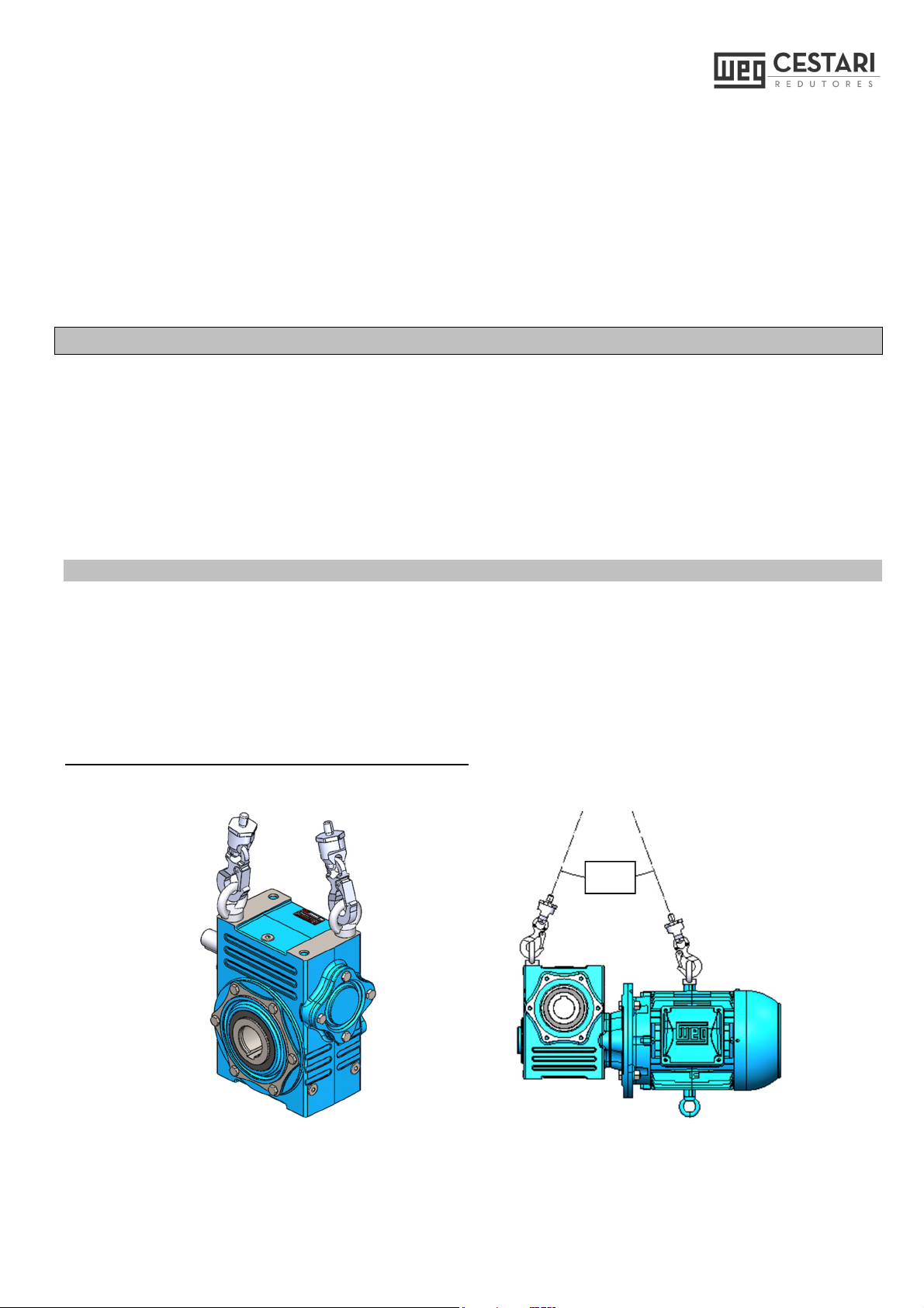
3Transport ................................................................................................................................................. 7
3.1Moviment.............................................................................................Erro! Indicador não definido.
4Storage..........................................................................................................Erro! Indicador não definido.
4.1Period without operation......................................................................Erro! Indicador não definido.
4.2Long Term Storage .............................................................................Erro! Indicador não definido.
4.3Storage Preparation ............................................................................Erro! Indicador não definido.
4.4Operation after Storage.......................................................................Erro! Indicador não definido.
5Installation ............................................................................................................................................. 10
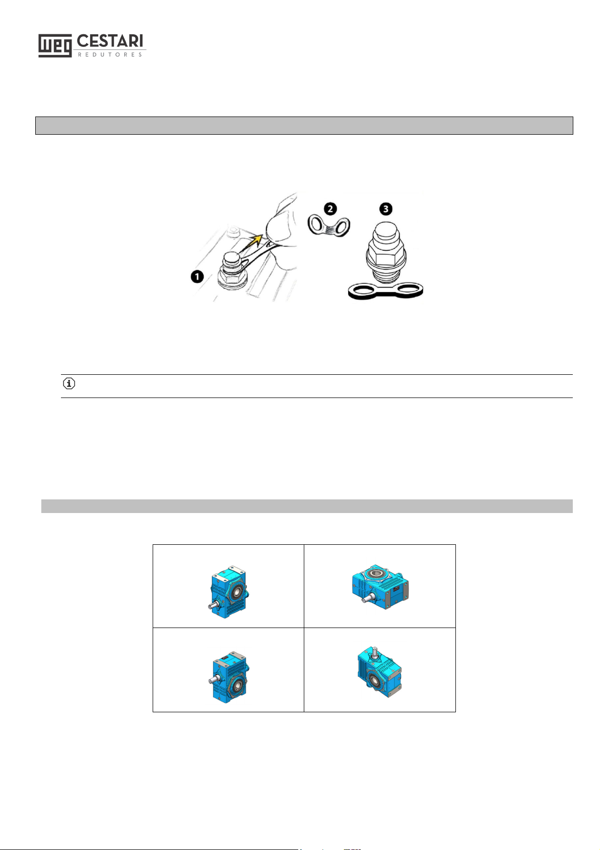
5.1Example of Working Position ..............................................................Erro! Indicador não definido.
5.2Minimum permissible diameter for the drive element mounted on the shaftErro! Indicador não
definido.
5.3Mounting position of notched hub .......................................................Erro! Indicador não definido.
5.4Axial clearance for bearing mounting ............................................................................................... 13
6Lubrication ...................................................................................................Erro! Indicador não definido.
6.1Operating temperature and oil temperature ........................................Erro! Indicador não definido.
6.2Quantity of lubricant Magma M Line................................................................................................. 16
6.3Lubricant quantity Alumag line ......................................................................................................... 16
6.4Quantity of lubricant Magma K Line ................................................................................................. 16
6.5Quantity of lubricant 1st stage of the duplex gearboxes Magma K line .......................................... 17
6.6Recommended synthetic lubricants ................................................................................................. 17
6.7Recommended mineral lubricants.................................................................................................... 17
6.8Check list - Installation and assembly of gearboxes ........................................................................ 18
7Operation ......................................................................................................Erro! Indicador não definido.
8Maintenance .................................................................................................Erro! Indicador não definido.
8.1Maintenance Task List ........................................................................Erro! Indicador não definido.
8.2Gearbox faults .....................................................................................Erro! Indicador não definido.
9Repairs..........................................................................................................Erro! Indicador não definido.
9.1Compact Single Input Assembly ...................................................................................................... 23
9.2Compact single entry list .................................................................................................................. 24
9.3Compact Dual Input Assembly ......................................................................................................... 25
9.4Compact dual entry list...................................................................................................................... 26
9.5Single input Assembly ...................................................................................................................... 27
9.6Simple Input List............................................................................................................................... 28
9.7Dual Input Assembly ........................................................................................................................ 29

Worm Gearbox line
9.8Dual entry list.......................................................................................Erro! Indicador não definido.
9.9Adaptation Accessories.................................................................................................................... 31
9.10List Adaptation Accessories .............................................................Erro! Indicador não definido.
9.11Compact input assembly............................................................................................................... 33
9.12Compact Input List ........................................................................................................................ 34
9.13Adaptations Alumag accessories .................................................................................................. 35
9.14List Adaptations Alumag Accessories ...........................................................................................36
10Warranty term...............................................................................................Erro! Indicador não definido.
11Environmental guidelines ...........................................................................Erro! Indicador não definido.

4 | Worm Gearbox line
1 General Considerations
The purpose of this manual is to provide important information that must be observed when transporting,
storing, installing, operating and maintaining WEG-CESTARI products (gear units, gear motors, parts, and
parts) and we, therefore, recommend that you carefully read the instructions contained herein. Failure to
observe the instructions in this manual, in the motor manual (if supplied), voids the product warranty and may
result in serious personal injury and property damage.
In the case of geared motors supplied with a WEG motor, the Motor Installation, Operation and Maintenance
Manual is attached to this manual and must also carefully observe.
The gearboxes supplied with a nameplate (Fig.1) and the geared motors supplied with two nameplates, one
from the gearbox (Fig..1) and one from the motor (according to the manufacturer's standard). The nameplates
contain symbols and values that determine the characteristics of the gearbox and the motor. They fixed in an
easily visible place; they made of weather-resistant material.
The data on the gearbox nameplate are:
Code: Gearbox or geared motor code.
Serial: Serial number.
P1: Motor or gearbox power (kW).
rpm: Gearbox output speed.
M2: Output torque (Nm).
sf: Service factor.
i: Total reduction.
Weight: Weight of the gearbox without motor
(kg).
Oil: Type and viscosity of the oil at 40ºC.
P: Working position and Year of manufacture.
TAG: Information Space
Figura 1
.
The geared motors and gearboxes supplied painted with WEG-CESTARI standard synthetic enamel or
according to specific customer requirements.

Worm Gearbox line
1.1 Safety instructions and information
1.2 General information
This documentation is an integral part of the product and must be read carefully. The information is intended
for all people involved in the assembly, installation, operation, and maintenance of the product and must be
followed.
We do not accept any liability for damage or interruptions of operation resulting from non-compliance with this
documentation.
In the interest of future development, we reserve the right to make modifications and adjustments to this
document without prior notice.
If you have any questions or would like further information, please contact WEG-CESTARI Redutores e Motor
reducutores S.A.
Intended use:
Geared motors are exclusively designed to generate a defined rotary motion in machines and equipment.
Any use other than this is considered unintended use.
The user/operator of the machine or equipment is solely responsible for damage resulting from this.
The details of this manual, the nameplate, and other technical documentation must be considered and
observed.
Intended use for motors:
The motors are designed for operation with power and also in combination with frequency inverters.
Standard motors are designed for use in:
Ambient temperatures from -20°C to +40°C
Altitudes ≤1000 m above sea level.
All safety and warning instructions must be followed without exception!
WARNING!
Warning of electrical or mechanical danger.
ATTENTION!
Important instructions for safe and trouble-free operation.

6 | Worm Gearbox line
This information can also be found on the motor nameplate
.
1.3 Exclusion of liability
The information contained in this Instruction Manual must be followed to ensure the safe and flawless
operation of the Geared motor and to achieve the specified product characteristics and performance
requirements.
WEG-CESTARI assume no responsibility for damage to persons, equipment or property resulting from non-
compliance with this instruction manual. In these cases, any liability for defects is excluded.
1.4 Copyright and protection rights
Todos os documentos técnicos são protegidos de acordo com a lei de direitos autorais. O processamento,
reprodução e divulgação deles, mesmo que em partes, assim como outra utilização não é permitida, salvo
com concessão expressa por escrito.
2 General safety
The customer is responsible for installing the unit following good engineering practice.
The instructions in these Operating Instructions must be followed to achieve the characteristics of the drive
units and to ensure approval in case of warranty claims.
Make sure that no damaged products are put into operation!
Read these Operating Instructions carefully before starting any adjustment, installation or maintenance.
Installation, commissioning, maintenance, and repair of the Geared motor and electrical accessories may
only be carried out by qualified personnel under the following items:
Operating Instructions
Information labels/labels on the Geared motor
All other project documents, installation manuals, and operation manuals
Geared motor specifications and requirements belonging to the Geared motor
The applicable regional and national safety and accident prevention regulations..
WARNING!
Work is only allowed:
With the drive stopped,
When disconnected and prevented from being turned on again.

Worm Gearbox line
The protection around rotating parts must be observed in the installation project of the equipment to be
actuated to protect people and prevent accidents.
The operation of the drive unit by means of a frequency inverter may only take place if the specifications
shown on the motor nameplate are observed.
3 Transport
We recommend that when you receive our product (gearbox, geared motor and/or parts and accessories), you
check that it is in good condition and that it corresponds to your specifications.
If any damage has been found to the product, we request immediate formal communication of the fact to the
shipping company and WEG-CESTARI.
No installation work should be started before the problem encountered is resolved.
3.1 Movement
Use appropriate ropes, cables, belts and suspension equipment when moving the gearboxes/geared motors
so as not to endanger human lives and the equipment itself..
The gearboxes must be moved using the suspension screw (Fig.2A) and, when it is a geared motor, it must
be moved together with the motor eyebolt (Fig.2B) respecting the maximum angle of 60º between the cables.
Never suspend the equipment only through the motor.
Figure 2A
Figure 2B
60º

8 | Worm Gearbox line
Before fully lifting the gearboxes/geared motor make sure that the load is properly balanced. All handling of
the gearbox/geared motor must be carried out in a gentle manner to avoid impacts and damage especially
to the shaft ends.
4 Storage
WEG-CESTARI products (gearboxes, geared motors, parts, and parts) must be stored in their original
packaging in a closed environment (not directly exposed to sunlight or UV rays), dry, protected against insects,
free of dust, air humidity below 60%, free of gases, fungi, corrosive agents (contaminated air, ozone, gases,
solvents, acids, alkaline, salts, radioactivity, etc) and ambient temperature between -5ºC to +40ºC.
WEG-CESTARI gearboxes must be stored in the specified and supplied working position, on a flat surface on
platforms or appropriate shelves (not in direct contact with the floor) and not in a place with vibration and
oscillations.
4.1 No operation period
WEG-CESTARI gearboxes/motors leave the factory and must be put into operation within a maximum
period of 6 months.
For periods of 6 months to 9 months without operation, it is recommended to fill the entire interior of the gear
unit with appropriate lubricants (see chapter Lubricants). Fill the reducer with oil up to the top (just below the
vent), thus ensuring that all its gears and bearings are immersed in oil. The input shaft of the reducer must
be rotated at least two complete turns and this procedure must be repeated at least once every 2 months.
NOTE:
For the appropriate lubricant volume, refer to chapter "Lubrication".
Protect the retainers externally with grease and apply a thin layer of grease to the external surface to prevent
drying out. The grease should be removed before starting operation (recommended grease NLGI#2EP
Texaco Multifak EP2 or similar).
4.2 Long-term Storage
The following are guidelines for cases of long-term storage or shutdown, i.e., more than 9 months without
operation. These guidelines are recommended for the storage of up to 2 years. If the relative humidity of
the air is less than 50%, the WEG-CESTARI product can be stored for up to 3 years.
Since there may be influences on the gearbox depending on local conditions, the time indications may vary
from those mentioned above.
If in doubt, contact WEG-CESTARI.

Worm Gearbox line
4.1 Preparation for Storage:
a) Remove all moisture from the gearbox;
b) Check the oil level and complete if necessary with the lubricant recommended in the product
manuals;
c) On gearboxes supplied with lubricating oil, add VCI (Volatile Corrosion Inhibitor) anticorrosive agent
to the lubricant to the extent of 2% of the lubricating capacity.
d) In the case of gear geraboxes supplied without oil, mix 10% of the total volume of the lubricant
recommended in the manuals with 2% of this total volume of VCI and fill the reducer. VCI additive
reference MV OIL 1061 (http:// www.vcibrasil.com.br).
Mineral oil already with VCI (Castrol Alpha SP 150 S or Castrol Alpha SP 220 S);
e) Seal the gerabox completely by hermetically closing the air holes (vents) and the area around the
level dipstick with an adhesive tape (if level dipstick is present);
f) Place grease around the shafts near the retainers and then wrap the shaft areas near the retainers
with an adhesive tape leaving the shaft flush with the retainers;
g) For external fastening surfaces (shafts and flange faces) they are Factory protected; inspect and
protect these surfaces if necessary (in case of film loss) with appropriate corrosion protection (Castrol
Safecoat DW 801 Corrosion Protection Oil or similar layer of approximately 50 μm). Any damage
caused by transport must be corrected.
h) If the gearbox is stored outdoors, place it on blocks. Make a frame around it (if possible) and cover it
with tarpaulin (cotton wax is recommended). Leave the bottom open to receive ventilation.
4.2 Operation after Storage:
If the storage or stop time exceeds 2 years or the ambient temperature deviates from the normal range
during storage, the gear unit lubricant must be replaced before commissioning.
Since they have been properly lubricated, the retainers must be replaced after 2 (two) years.
a) Remove any tape used in preparation for storage;
b) Remove any moisture that may have accumulated in the gearbox, clean the gearbox and inspect for
damage;
c) The VCI corrosion protection agent is soluble in recommended lubricating oils and does not need to
be removed from the gearbox;
d) Check this manual for recommended lubricants and installation, maintenance and operating
instructions;
e) In case the gear reducer is filled with oil, the amount of oil must be reduced to the recommended
amount before commissioning. See chapter "Mounting positions and lubricant quantities".
If required, gearbox prepared for "long-term storage" can be supplied. In this case, WEG-CESTARI must be
informed during the quotation and purchase process.
For storage periods longer than 9 months, the gearboxes/geared motors may only be put into operation if
the above procedures have been followed.

10 | Worm Gearbox line
5 Installation
For geared motors supplied with a rubber-sealed vent valve for transportation, before operating the geared
motor/gearbox, completely remove the protective rubber installed in the valve (as shown below):
After this procedure the vent valve is ready to operate.
The shaft ends are protected with a thin layer of anti-corrosion oil. This oil should be removed before
installation using normal solvents (varsol, turpentine or similar).
Attention !
The solvent must not reach the retainers and never use sandpaper to remove the varnish.
Geared motors / gearboxes must be installed in the correct working position (as stated in the Commercial
Proposal) on a flat, rigid base (to avoid additional stresses and strains), allowing easy access to the
lubrication devices.
5.1 Example of Working Position
Position-1
Position-4
Position-2
Position-5

Worm Gearbox line
Position-3
Position-6
5.2 Minimum permissible diameter for the drive element mounted on the shaft
Where: F = Effective radial load (N).
Pc = Effective power required by the machine (KW).
Dp = Primitive diameter of the element (mm).
n 2 = Rotation on the output shaft (rpm).
K = Correction factor.
Values for the k-factor:
Cogwheels...........................................: 1,0
Pinion and Gear ................................: 1.25
Belt V....................................................: 1,50
Flat Belt.............................................: 2.5
*For correct calculation, please refer to the catalog.
The elements to be mounted on the shafts, such as: couplings, pulleys, cogwheels, etc., must have the holes
machined with H7 tolerance, their weights and dimensions compatible with the gearbox and assembled with
slight interference, and must be as close as possible to the shaft backrest, as shown below:

12 | Worm Gearbox line
The use of a hammer in the assembly of these elements can damage the bearings and teeth of the gear
gearbox's worm.
The elements mounted on the shafts must be carefully aligned (even if it is an elastic coupling) to avoid
vibrations and additional forces. It is convenient to heat the part to be assembled up to about 100ºC; it can be
used the hole of threaded center in the end of the gearbox shaft in the assembly aid, making then the necessary
locking to avoid axial displacements of the transmission element.
ATTENTION! In accordance with the accident prevention regulations, protect all rotating parts by
means of protections installed against unwanted contact and against falling objects on the transmission
element, complying at least with the protection requirements (in Brazil according to NR12 standard and/or
according to work safety standard applied to the country where the product will be installed and used).
In the case of gearboxes/geared motors with a hollow shaft, do not mount the gearbox/geared motor to the
device by means of blows. To avoid contact oxidation and assembly difficulties, it is recommended to apply
and spread antioxidant greases (such as Dow Corning Molykote G-Rapid Plus or similar) on the shaft, housing
and keyway.
5.3 Mounting position of the notched hub
Gearboxes and Geared motors supplied with a torque arm must be guided axially and radially along the shaft
of the equipment and fixed by the torque arm; anti-vibration dampers compensate for oscillations in the radial
direction of the gearbox (see figure below):

Worm Gearbox line
If the gearboxt/geared motor is repainted for any reason, the retainers must be insulated to prevent the paint
from drying out, which causes the retainers to leak.
The fan and motor fans must be kept clean and free to allow perfect cooling; the distance between the air inlet
and the wall must be at least 30 mm.
The equipment where the geared motor or gearbox is being fixed must provide a correct positioning of the
fixing holes, observing that all the flange holes or gearbox feet must be used, so that there is no concentration
of efforts.
The keyway of the geared motor or gearbox is in accordance with DIN 6885 (Flat keys - DIN 6885 standard
sheet 1) and the metric thread of the tip in accordance with DIN 332 (centre 60° holes with metric thread - DIN
332 standard sheet 2 form D).
Check that the gearbox's working position and mounting are correct. Check that all fixing screws are correctly
tightened. When the gearboxes are put into operation, they must work without load for some hours; if there is
no abnormality, the load is gradually placed until reaching its total.
NOTE: The items listed above are valid only for the proper functioning of the gearbox, leaving the specifications
for general operation to the equipment manufacturer
5.4 Axial clearance for bearing mounting
size
Simple reduction gearboxes
Double reduction gearboxes
Input
Output Input Output
Normal Shaft Hollow Shaft 1º Stage 2º Stage Normal Shaft Hollow Shaft
14 0,16 - 0,18 0,01 - 0,03 0,01 - 0,03 0,08 - 0,09 0,03 - 0,04 0 - 0,02 0 - 0,02
17 0,18 - 0,20 0,01 - 0,03 0,01 - 0,03 0,10 - 0,12 0,04 - 0,05 0 - 0,02 0 - 0,02
20 0,14 - 0,16 0,02 - 0,04 0,02 - 0,04 0,12 - 0,14 0,03 - 0,04 0 - 0,02 0 - 0,02

14 | Worm Gearbox line
24 0,16 - 0,18 0,02 - 0,04 0,02 - 0,04 0,14 - 0,16 0,03 - 0,04 0 - 0,02 0 - 0,02
28 0,18 - 0,20 0,02 - 0,04 0,02 - 0,04 0,16 - 0,18 0,04 - 0,05 0 - 0,02 0 - 0,02
34 0,20 - 0,22 0,02 - 0,04 0,02 - 0,04 0,18 - 0,20 0,04 - 0,05 0 - 0,02 0 - 0,02
6 Lubrication
Proper lubrication is responsible for the performance and service life of the gearbox/geared motor. The
gearboxes are lubricated by oil bath and equipped with a level indicator plug, which can be a level gauge or
a hexagonal plug model HN10-WD (similar to DIN 510), differing from the other plugs in the gearbox/geared
motor.
The correct oil level is in the center of the sight glass (when of the "level glass" type) or in the plug level (when
of the hexagonal plug type) with the gearbox stationary and in the required working position.
Before starting operation, check that the gearbox is filled with oil and that the lubricant level is adequate as
recommended.
The operating temperature is the temperature of the lubricating oil after the temperature stabilization period
at full load (period after approx. 3 hours of continuous operation).
The minimum ambient temperature for the start of operation of gearboxes and geared motors depends on the
viscosity and type of lubricating oil.
The table below shows the minimum ambient temperature for the start-up of gearboxes and geared motors:
Oil MINIMUM TEMPERATURE
Type Viscosity Lubrication Lubrication
Mineral CLP ISO VG 220 +2°C +8°C
ISO VG 320 +7°C +14°C
Synthetic CLP
HC (PAO)
ISO VG 220 -5°C +2°C
ISO VG 320 0°C +8°C
ISO VG 460 +6°C --- ---
Contact WEG-CESTARI for other temperatures.
The external temperature of the housing is approximately 15°C lower than the operating temperature (oil
temperature).
When changing gears, the oil must be drained while still "warm" because the viscosity of the oil is lower,
facilitating the draining and cleaning.
NOTE: The lubricant used must be disposed of in accordance with current legislation and the guidelines
contained in the Environmental Guidelines chapter of this manual.
When changing gears, use the same oil as indicated on the gearbox nameplate and specified in this manual.
It is not recommended to mix oils of different types and manufacturers.
The oil must be changed every 3500 hours or annually.

Worm Gearbox line
6.1 Operating temperature and Oil temperature
The operating temperature is the temperature of the lubricating oil after the temperature stabilization period
at full load. (period after approximately 3 hours of continuous operation)
The external temperature of the housing is approximately 15 °C lower than the operating temperature (oil
temperature).
The operating temperature for WEG-CESTARI gearboxes is a minimum of 18°C and a maximum of 90°C
(under normal operating conditions).
In the first 500 hours it is recommended to observe the quality of the oil, if it is contaminated or with particles
must be replaced.
When changing, the oil must be drained while still hot in order to facilitate draining and cleaning.
In case of unfavorable environmental conditions (high humidity, aggressiveness, dust), the change time can
be reduced, in this case under consultation.
When changing gearboxes, the same oil must be used as indicated on the gearbox nameplate and specified
in this manual.
Do not mix oils of different types and manufacturers. The oil change time is defined as a function of the
operating temperature - see table below
Operating
temperature
Mineral Oil
CLP
Synthetic Oil
CLP HC
Hydrocarbons
Synthetic Oil
CLP PG
Polyglycol
80 °C 5.000 hours 15.000 hours 25.000 hours
85 °C 3.500 hours 10.000 hours 18.000 hours
90 °C 2.500 hours 7.500 hours 13.000 hours
95 °C --- --- 6.000 hours 8.500 hours
100 °C --- --- 3.800 hours 6.000 hours
105 °C --- --- 2.500 hours 4.000 hours
110 °C --- --- 2.000 hours 3.000 hours
NOTE: The nameplate informs the type of oil recommended for the gear unit (CLP=Mineral; CLP
HC=Synthetic; CLP PG= Synthetic).

16 | Worm Gearbox line
6.2 Quantity of lubricant Magma M line
SIMPLE Size 03 04 05 06 07 08 10 12
Volume 0,3 0,27 0,65 0,87 1,2 1,68 2,74 3,9
DUPLEX Size 05(04) 06(04) 07(04) 08(05) 10(05) 12(06) ---- ----
Volume 0,65/0,27 0,87/0,27 1,2/0,27 1,68/0,65 2,74/0,65 3,9/0,87 ---- ----
* The quantities of oil (liters) specified in the table above include all working positions..
6.3 Quantidade de lubrificante Linha Lubricant quantity Alumag line
SIMPLE Size L03 L04 L05
Volume 30 ML 50 ML 70 ML
DUPLEX Size L04/L03 L04/L05 L05/L03
Volume 50 ml / 30 ml 50 ml / 70 ml 70 ml / 30 ml
6.4 Quantity of lubricant Magma K line
Size
Working position
Normal double shaft
Working position
Hollow shaft
Posição 1 2 3 e 4 5 e 6 1 2 3 e 4 5 e 6
14 3,6 8,0 5,6 6,3 3,6 7,0 5,0 5,7
17 5,2 12,0 8,2 9,5 5,2 10,5 7,4 8,8
20 12,0 20,0 15,5 16,0 12,0 20,0 16,0 17,0
24 18,0 26,0 21,5 22,0 18,0 26,0 22,0 23,0
28 30,0 40,0 36,0 38,0 30,0 40,0 38,0 38,0
34 50,0 70,0 60,0 62,0 50,0 70,0 62,0 62,0
*
Magma K series gearboxes are supplied without lubricant as standard. For cases where the customer
requests the gearbox with oil, this must be described in the sales order and must follow the quantity
indicated above.
For the Magma K line (only fill the oil up to the level plug).

Worm Gearbox line
6.5 Quantity of lubricant 1st stage of the duplex gearboxes Magma K line
6.6 Recommended synthetic lubricants
Manufacturer Viscosity mm2/s Lubricant Type
(C St) a 40ºC Maximum oil time
ISO - NLGI 90ºC
ExxonMobil VG 460 SHC 634
Shell VG 460 OMALA S4GX 460
Klüber VG 460 KLUBER SYNTH - EG4-460
Klüber VG 460 Syntheso D460 EP
Petrobrás VG 460 Lubrax Syntesis Gear 0 - 460
6.7 Recommended mineral lubricants
Viscosity and Lubricant Type
AGMA 7 EP AGMA 8 EP Greases for
Manufacture
r
-10ºC a 10ºC 10ºC a 50ºC bearings
Petrobrás Lubrax Industrial
EGF 460
PSLubrax Industrial EGF 0
PS Lubrax GMA - 2
Ipiranga Ipiranga SP 460 Ipiranga SP 680 Ipiflex 2
Esso Spartan EP 460 Spartan EP 680 Beacon 2
Texaco Meropa 460 Meropa 680 Multifak
Atlantic Pennant 460 Pennant 680 Litholine 2
Shell Omala 460 Omala 680 Alvania 2
Mobiloil Mobilgear 634 Mobilgear 636 Mobil Grease MP
PROMAX G.O. 140 G.O. 250 Bardahl Purpose Grease
CHEMLUB - Gear 680 UD-90 Especial
Size K14 K17 K20 K24 K28 K34
Position 1 2 4 5 6 1 2 4 5 6 -- -- -- --
Volume 3,6 7,0 5,0 5,7 5,2 10,5 7,4 5,7 -- -- -- --

18 | Worm Gearbox line
6.8 Check list – Installation and assembly of gearboxxes
Receipt
Checked
Paint Verification
Check for scratches,
p
eelin
g
and other im
p
erfections.
Oxidation Verification
Check for the presence of oxidised points or areas on the gearbox and/or accessories.
Leakage Verification
Check for the presence of oil in seals, caps and joints.
Machined Parts Protection Verification
Check that machined parts are protected with protective oil.
Component Verification
Check if components used in the assembly are present.
Seals Verification
Check that the vent valve is sealed.
Verification of storage conditions
Check that the gearbox has been conditioned according to the instructions in the product
manual.
IInstallation Verificado
Checking the Working Position
Check that the gearbox is mounted in the position for which it was supplied.
Lube Oil Level Check
Check the lubricating oil level according to the product manual.
Vent Valve Seal Removal Check
Check that the vent valve seal has been completely removed before putting the gearbox into
operation.
Verification of Sealing Elements
Check seals, caps and other sealing elements for leaks and/or deformities of these elements.
Checking the gearbox installation
Check that the gearbox has been placed on the driven machine in accordance with the
recommendations of the product manual.
Application of Protective Oil in Machined Parts
Check whether protective oil has been applied to the machined parts after installing the
gearbox in the machine.

Worm Gearbox line
7 Operation
Before starting operation, check that the gearbox is filled with oil and that the lubricant level is adequate as
recommended.
Make sure that the geared motor/gearbox rotates freely. Make sure that the connection diagram is as shown
on the motor nameplate for the required voltage.
ATtention!
Standard motors are suitable for clockwise and counterclockwise rotation. Connecting the power cables in
phase sequence L1, L2, L3 to U1, V1, W1 results in clockwise rotation (looking at the shaft end on the drive
side).
If the two connections are changed the rotation will be counterclockwise (e.g. L1, L2, L3 to V1, U1,
W1).
Identify the desired direction of rotation by activating the geared motor uncoupled from the equipment if
reversal of the direction of rotation is necessary must reverse any two phases.
Check that the screws, nuts and connections of the motor terminals and the gearbox fixing screws and nuts
are properly tightened.
For geared motors/gearbox supplied with a rubber-sealed vent valve for transportation, completely remove
the protective rubber installed in the valve before the geared motor/gearbox is operated (as shown below):
After this procedure, the vent valve is ready to operate.
When the gearbox starts operating, the oil temperature gradually rises until it stabilizes after approximately
3 hours, reaching the operating temperature.
8 Maintenance
The main purpose of periodic preventive maintenance is to check the operating conditions of the geared
motor/gearbox. It must be performed by qualified people.
There are no strict rules to be followed when addressing inspection programs. The periods and types of
examinations to be carried out can be extended or reduced according to the working conditions and location
where the gearbox/geared motor is installed.

20 | Worm Gearbox line
It is recommended that each geared motor/gearbox has some type of note of its own, such as plug, cards or
label. To register all the maintenance performed, the parts exchanged and the dates on which they were
performed.
In the following topic is presented a basic program for inspection containing the items to be inspected and
the suggested time intervals; such intervals are flexible, in the following topic is according to the conditions
of the place where the geared motor/gearbox is installed:
8.1 Maintenance Task List
Table of contents
Other WEG Circuit Breaker manuals