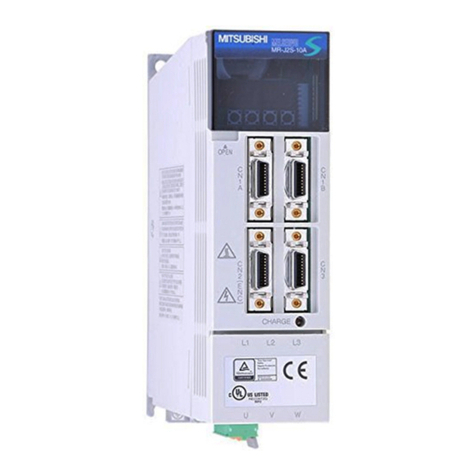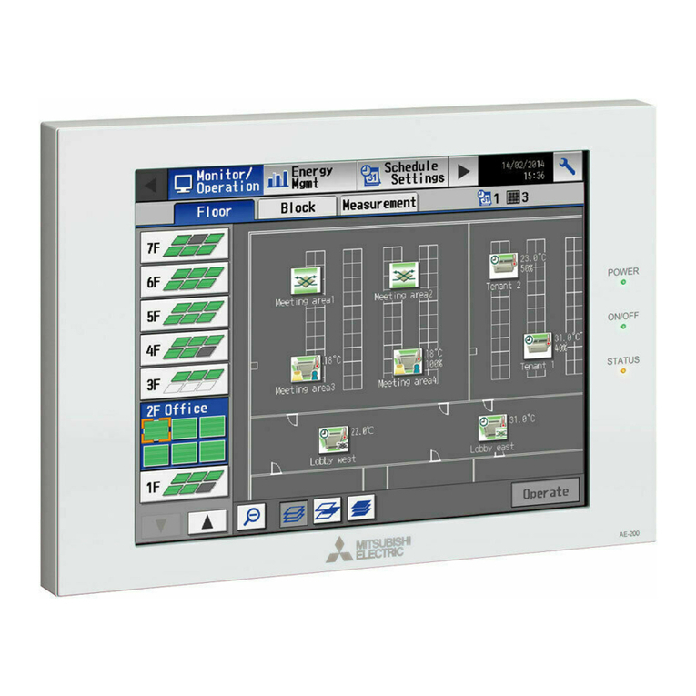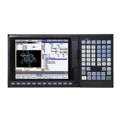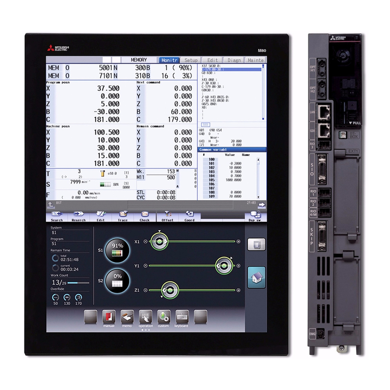
System Remote Controller PAC-SF44SRA
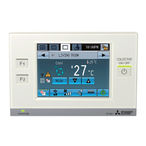
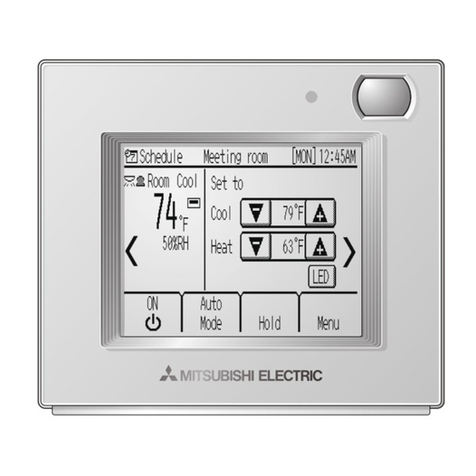
Schedule Timer PAC-YT34STA
ON/OFF Remote Controller PAC-YT40ANRA
This manual describes only the installation of the System Controller, capable of managing and controlling air conditioners, and LOSSNAY. Refer to
the installation manuals enclosed with the air conditioner for details on wiring and installing the air conditioner unit.
To ensure safety, always read below before starting installation.
•The following two symbols are used to denote dangers that may be caused by incorrect use and their degree:
WARNING
CAUTION
This symbol denotes what could lead to serious injury or death if you misuse above remote controllers.
This symbol denotes what could lead to a personal injury or damage to your property if you misuse above remote controllers.
•After reading this installation manual, keep it in a place where the final user can see it anytime he or she wants to it.
When someone moves, repairs or uses above remote controllers, make sure that this manual is forwarded to the final user.
Ask your dealer or technical representative to install the unit.
Never modify or repair above remote controllers.
Do not move and re-install above remote controllers yourself.
Do not install in any place exposed to flammable gas leakage.
Wire so that it does not receive any tension.
Do not touch any control button with your wet hands.
WARNING
CAUTION
Do not wash with water.
When installing the remote controller in a hospital or communication facility, take ample countermeasures against noise.
Do not touch any PCB (Printed Circuit Board) with your hands or
with tools. Do not allow dust to collect on the PCB.
Do not install in any steamy place such a bathroom or kitchen.
Do not remove the insulation sheet on the PCB.
Do not press any control button using a sharp object.
Never apply 100VAC or 200VAC. The maximum voltage that can
be applied on this unit is 30VDC.
Completely seal the wire lead-in port with putty.
Install in a place which is strong enough to withstand the weight
of above remote controllers.
!
Firmly connect the wiring using the specified cables. Carefully
check that the cables do not exert any force on the terminals.
"
Ensure that installation work is done correctly following this
installation manual.
All electrical work must be performed by a licensed technician,
according to local regulations and the instructions given in this
manual.
#
Do not use in any special environment.
Do not install in any place where acidic or alkaline solution or
special spray are often used.
Use standard wires in compliance with the current capacity.
$% % %
& %
Do not install in any place at a temperature of more than 40; or
less than 0; or exposed to direct sunlight.
Confirm that the box includes the following parts, in addition to this installation manual:
(1) Remote controller (Body, lower case) ........................................................
(2) Cable for external input (5 wire) .................................................................
(3) Cable for external output (4 wire)...............................................................
(4) Cross recessed pan head screw (M4
30) ...............................................
(5) Wood screw (4.1
16, used for directly hooking to the wall).....................
(6) Room name label or room name record sheet...........................................
(7) Operation Manual.......................................................................................
2 Confirming the Supplied Parts
NOTE:
The remote control cord is not supplied with the product.
Prepare electrical wiring that conforms to the specifications given below.
Electrical wiring specification (CVVS)
Use 1. 5mm cable for any extension that exceeds 10m.
¥ 10m or shorter : 0.75mm two-wire cable
¥ Longer than 10m : 1. 5mm two-wire cable
Remote controller wiring entry points can support electrical
wiring of maximum 1. 5mm .
However 0.75mm electrical wiring is recommended for use.
(Refer to the "System Design and Work Manual" for the outdoor unit for details.)
!"
(1) When connecting to a central management transmission line
A power supply unit (PAC-SC34KUA) is required.
* The power consumption of the system controller, schedule timer and group remote controller is half of the ON/OFF remote
controller. Thus, interpret the power consumption per unit as half of the ON/OFF remote controller.
!
"
#
Schedule timer
PAC-YT34STA
ON/OFF
remote controller
PAC-YT40ANRA
[051]
CN41
Leave as is
TB7 TB3
1
SW2-1[ON]
ON
OFF
234 5678910
Group 2
[003]
[002]
[001]
[005]
[004]
[006] [007]
[009]
[101] [102] [103]
[105] [106] [107]
[201] [202] [203]
Group 1 Group 3
Group 4 Group 7
Group 6Group 5
System
remote controller
PAC-SF44SRA
[008]
[108]
Power supply unit
Model: PAC-SC34KUA
[052]
CN41
TB7 TB3
1
SW2-1[ON]
* Outdoor unit
: SW position
ON
OFF
234 5678910
Leave as is
* Number of units that can be supplied with power supply unit (For above system)
One system remote controller One schedule timer One ON/OFF remote controller
1×1/2 + 1×1/2 + 1×1 = 2 (unit)
(2) When connecting to indoor and outdoor transmission line
Up to three system controllers can be connected to the M-NET transmission line's indoor and outdoor transmission line.
A power supply unit is not required in this case, but the short-circuit connector of one of the connected outdoor units must be
connected to CN40.
(3) Setting the various M-NET addresses
The need for address settings and the address setting range will differ according to the system configuration. (The address can-
not be set in duplicate).
(4) Setting the system controller address
(5) When using with master system controller
When connecting multiple system controllers, the system controller with many functions is designated as the "master", and the
system controllers with few functions are designated as the "slaves". The "master/slave" functions of the system controller used
together are as follows.
The functions have a priority in order of G50A (MJ-103MTRA) > PAC-SF44SRA > PAC-YT34STA > PAC-YT40ANRA > PAC-SC30GRA > LMAP02-E.
NOTE :
CAUTION
When the system remote controller is connected to the indoor and outdoor transmission line, the number of indoor units
that can be connected in that refrigerant system will be reduced by two.
When connecting the system controller to the indoor and outdoor transmission line, operations from the
system controller will be disabled if the outdoor unit's power is turned OFF, etc.
Schedule Timer
PAC-YT34STA
ON/OFF
remote controller
PAC-YT40ANRA
Group 2
[003][002][001]
[005]
[004]
[006] [007]
[009]
[101] [102] [103]
[105] [106] [107]
[201] [202] [203]
Group 1 Group 3
Group 4 Group 7Group 6Group 5
System
Remote Controller
PAC-SF44SRA
[008]
[108]
[051]
CN40
Interchange
short-circuit
connector from
CN41 to CN40.
TB7 TB3
1
SW2-1[ON]
ON
OFF
234 5678910
* Outdoor unit
: SW position
[052]
CN41
Leave as is
TB7 TB3
1
SW2-1[ON]
ON
OFF
234 5678910
System controller
Address setting range
201 to 250
201 to 250
201 to 250
Setting method
Random within address range shown on left
Random within address range shown on left
Set to the minimum group No. to be controlled + "200"
System remote controller
Schedule timer
ON/OFF remote controller
Default address setting
201
202
201
NOTE :
CAUTION
When setting the address, prepare a precision screwdriver
[( ), 2.0mm (w)], and keep the applied load to less than
19.6N.
etting with other methods could damage the rotary switch.
¥ The address No. that can be set on the remote controller is
within the range of 201-250.
The 100 digit is fixed at "2".
¥Ifanaddress other than those listed above is set, an address
setting error occurs and "AdE" is displayed.
Master side
Slave side
System remote controller (44SRA)/Schedule timer (34STA)
SW3-1: OFF
SW3-1: ON
ON/OFF remote controller (40ANRA)
SW4-1: OFF
SW4-1: ON
* The switch is set to "Master" as the factory setting.
When using the external input and output functions, use the external input and output cables provided with the remote controller.
(5 wire cable for input and 4 wire cable for output are provided.)
1. External signal input function
(1) External Input
Emergency stop/Normal, ON/OFF and Prohibit/Permit local remote controller operation control can be applied to all units
being controlled by inputting the no-voltage contact signal from an external source.
(2) Level signal and pulse signal
(3) External input specification
(4) Example of a recommended circuit
• The relays and extension cables, etc. must be prepared separately at the site.
• Use a no-voltage contact and minute load relay (minimum application load 5VDC-1mA).
• The length of the connection cable extension should not exceed 10m. (Use a cable of 0.3mm2or thicker.)
• Cut of the cable not being used close the connector and properly insulate the cut off ends with tape or the like.
4 Using the External Input and Output
No.
1
2
3
4
Do not use external input
Change between Emergency stop/Normal.
Set ON/OFF
Set ON/OFF and Prohibit/Permit.
Input state
—
ON/OFF remote
controller
SW4
2
Schedule timer
SW3
233
OFF OFFOFF OFF
Level input
Level input
Pulse input
(0.5sec or more)
OFF
ON
ON
ON
OFF
ON
System remote
controller
SW3
23
OFF OFF
OFF
ON
ON
ON
OFF
ON
OFF
ON
ON
ON
OFF
ON
External input signal functions
All units will stop with the external input,and all operations of this unit,other system controllers and
local remote controller will be prohibited.
All units will turn ON/OFF according to the input state. ON/OFF operations using this unit and the
local remote controller will be prohibited when using this function.
All units are started or stopped, or all local remote controller operations are prohibited according to
the input state. When prohibit is input, the local remote controller’s ON/OFF, operation mode, set
temperature and filter reset operations will be prohibited. Operation with this system will be enabled.
NOTE : For System remote controller and Schedule timer
* If the SW3-4 "operation prohibit setting changeover" is set to "OFF (disable)", use is possible only for emergency stop.
* If the SW3-5 "operation prohibit range setting changeover" is set to "ON (including system controller), operations of the local remote
controller and other system controllers will be prohibited by the prohibit input. If set to "OFF (only local remote controller)", operation
of only the local remote controller will be prohibited. (When the level "emergency stop" or "ON/OFF" is input, operation of the other
system controllers will also be prohibited regardless of the switch setting.)
For ON/OFF remote controller
* All units are stopped when emergency stop is input, and ON/OFF operations of this unit, other system controllers and local remote
controller will be prohibited.
* Only ON/OFF of the local remote controller will be prohibited with the prohibit input.
Contact ON
Contact OFF
Contact ON
Contact OFF
Contact ON
Contact OFF
Contact ON
Contact OFF
OFF OFFON
Normal Normal
Emergency
STOP OFF OFFON
(A) Level signal (B) Pulse signal
0.5sec or more
0.5sec or more
(Example) Case of ON/OFF signal
Signal 1 (ON)
Signal 2 (OFF)
* The same applies to Prohibit/Permit.
!!
"# $
#
%
&'
&'
('
(
!!
)
! "#$
! "#$ #%"
" %
" %
" %
&'
$((
$(( #%"
" %
" %
" %
)% $((* )+,"$)"
#%"
#%"
)+," " " #" #%"
)" " " #" #%"
For level signal
Contact operation
OFF ON
Operation state
Emergency stop/Normal
Normal Emergency stop
Emergency stop Normal
ON OFF
External input
For pulse signal
* Operation will continue even if a
ON
signal is input during operation. (This also applies to
OFF
, prohibit and enable).
*
If the local remote controller is prohibited, ON/OFF, operation mode, temperature and filter reset operations using the local
remote controller will be prohibited. (Only ON/OFF are prohibited for the ON/OFF remote controller.)
* Set the pulse duration (contact ON time) to 0.5sec or more.
ON/OFF
OFF ON
ON OFF
NOTE :
ENG_WT03799X01_A2(QX3_1e) 2/4/03 9:33 AM Page 1
