Sutter Instrument Lambda SC Quick guide

Lambda SC
Smart
Shutter®
Control System
USB Installation &
Configuration
Rev. 1.03 (20080617)
One Digital Drive
Novato, CA 94949
Voice: 415-883-0128 Web: www.sutter.com
Fax: 415-883-0572 Email:info@sutter.com

LAMBDA 10-B OPERATION MANUAL – REV. 0080617)
2
Copyright © 2008 Sutter Instrument Company. All Rights Reserved.
LAMBDA 10 ® and
Smart
Shutter®are registered trademarks of Sutter Instrument
Company.
1.03 (2


3
TABLE OF CONTENTS
1. GENERAL INFORMATION..............................................................................................................5
1.1 About this manual............................................................................................................................5
1.2 Technical Support.............................................................................................................................5
2. SAFETY WARNING...........................................................................................................................5
3. PRECAUTIONS..................................................................................................................................5
3.1 On operation......................................................................................................................................5
3.2 On use of high-intensity light sources............................................................................................6
4. REMOTE CONTROL.........................................................................................................................6
4.1 Input Command Structure..............................................................................................................7
4.1.1 Status.........................................................................................................................................10
4.1.2 More Information on Timers:.................................................................................................13
4.1.3 Get Controller Type and Configuration ................................................................................15
4.2 Remote Control Command Programming...................................................................................15
4.2.1 Preparing the Command Byte................................................................................................16
4.2.2 Command Transmission Protocol..........................................................................................16
4.2.2.1 Confirmation Command Echo.........................................................................................16
4.2.2.2 Command Completion Indicator .....................................................................................16
5. REMOTE CONTROL: USB Port....................................................................................................17
5.1 Installing the Lambda SC as a USB Device on a Windows System..........................................17
5.1.1 Installation Steps .....................................................................................................................17
5.1.2 Interactive USB Device Driver Installation (Windows Only).............................................18
5.2 Installing the USB Interface for Non-Windows Systems...........................................................21
5.3 Verifying USB Communication Between Remote Computer and Lambda SC.......................21
5.4 Uninstalling the USB Driver for the Lambda SC.......................................................................23
APPENDIX A: LIMITED WARRANTY.............................................................................................24
INDEX....................................................................................................................................................24
TABLE OF FIGURES
Figure 5-1 -- The USB cable device connector.......................................................................................18
Figure 5-2 -- The Lambda SC USB receptacle.......................................................................................18
Figure 5-3 -- Host connector end of USB cable.....................................................................................18
Figure 5-4 -- USB host receptacle on remote computer.......................................................................18
Figure 5-5 -- New USB device detected message box. ..........................................................................19
Figure 5-6 -- Digital Signature dialog box..............................................................................................19
Figure 5-7 -- Specifying location of driver files......................................................................................20
Figure 5-8 -- Browsing for the driver file needed..................................................................................21
LAMBDA SC USB INSTALLATION & CONFIGURATION – REV. 1.03 (20080617)

LAMBDA SC USB INSTALLATION & CONFIGURATION – REV. 1.03 (20080617)
4
Figure 5-9 -- USBTest main screen........................................................................................................22
TABLE OF TABLES
Table 4-1. Remote control command categories .....................................................................................6
Table 4-2. Remote control commands......................................................................................................7
Table 4-3. Status command return codes and data ..............................................................................10
Table 4-4. Timer command time encoding............................................................................................14
Table 4-5. "Get Controller Type and Configuration" command return codes and data....................15

1. GENERAL INFORMATION
1.1 About this manual
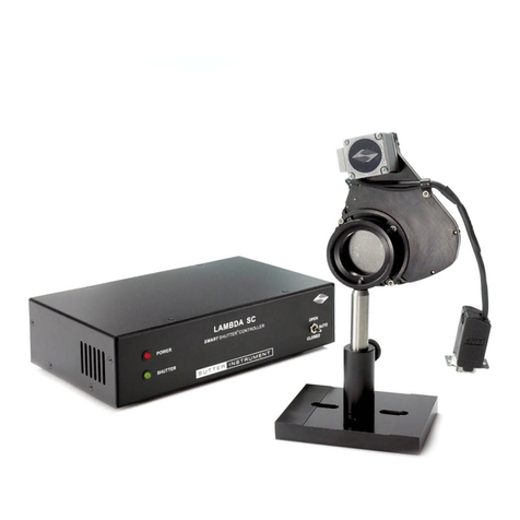
The Lambda SC is a system designed to control and drive a single SMARTSHUTTER. The
configuration and control of the Lambda SC is made via the USB port, and basic control is
possible via TTL triggering.
Refer to the REMOTE CONTROL section for instructions on how the USB connection to a
computer is made, how the USB device driver is installed. The next section also describes
the installation and running of a demo program that can be used to test the Lambda SC’s
USB connection, and to configure controller’s
SMART
SHUTTER settings.
1.2 Technical Support
Unlimited technical support is provided by Sutter Instrument Company at no charge to our
customers. Our technical support staff is available between the hours of 8:00 AM and 5:00
PM (Pacific Time) at (415) 883-0128. You may also E-mail your queries to info@sutter.com.
2. SAFETY WARNING
To prevent fire or shock hazard do not expose the unit to rain or moisture.
To avoid electrical shock and exposure to hazardous electrical voltages:
Do not disassemble the unit. Refer servicing to qualified personnel.
Always use the grounded power supply cord set provided to connect the unit to a
grounded outlet (3-prong). This is required to protect you from injury in the event that
an electrical hazard develops.
3. PRECAUTIONS
3.1 On operation
Failure to comply with any of the following precautions may damage this device.
Operate the Lambda SC using 110V a.c., 60Hz or 220V a.c., 50 Hz line voltage.
The Lambda SC is designed for operation in a laboratory environment (pollution degree
I).
The Lambda SC is designed for connection to a standard laboratory power outlet
(overvoltage category II).
Operate only in a location where there is a free flow of fresh air on all sides. NEVER
ALLOW THE FREE FLOW OF AIR TO BE RESTRICTED.
LAMBDA SC USB INSTALLATION & CONFIGURATION – REV. 1.03 (20080617)

6
Do not disconnect the cables between the controller and the mechanical units while
power is on. Please allow at least 20 seconds after turning the unit off before
disconnecting the mechanical units. Failure to do this may result in damage to the
electronics.
Since the Lambda SC is a microprocessor-controlled device, it should be accorded the
same system wiring precautions as any 'computer type' system. If microprocessor-based
systems in the lab require line surge protection for proper operation, then the same
protection should be provided for the Lambda SC.
3.2 On use of high-intensity light sources
Failure to comply with any of the following precautions may result in injury to the users of
this device as well as those working in the general area near the device.
Never look into the optical pathway of the high intensity light sources typically used with
this instrument. Doing so can cause permanent eye damage.
The high-intensity light sources typically used with this instrument also produce a
significant amount of heat. Direct contact with the housing of those instruments can
cause serious burns.
4. REMOTE CONTROL
The remote control of the Lambda SC can be achieved by issuing commands on a remote
computer and transmitting them to the Lambda SC over a USB (Universal Serial Bus) or RS-
232 serial connection. This chapter provides a description of these commands and how they
are used. Limited remote control can also be achieved with a TTL connection, a description
for which is provided later in this manual.
The following table shows how remote commands are categorized.
Table 4-1. Remote control command categories
Category Description
Shutter commands These are commands used exclusively for controlling the SmartShutter.
Special commands These are commands for the general control of the Lambda SC controller,
and are not specifically related to shutters.
Most of the commands described in this chapter are ones that are sent from the computer to
the Lambda SC. Some of these commands will cause the Lambda SC to return certain special
codes or one or more bytes of data. Some commands must be followed by one or more bytes
containing parameters. For each byte sent to the Lambda SC, that same byte is echoed
(transmitted) back to the remote computer as confirmation that the byte was received. This
echoing back of command bytes in no way indicates validation of a command or parameter,
but rather is an acknowledgement on the part of the controller that it has received the byte,
When the Lambda SC controller has finished performing the task associated with a command
(or command followed by one or more parameter bytes), the controller will transmit to the
host computer an ASCII carriage return (CR, 13 decimal, or 0D hexadecimal) as an indication
LAMBDA SC USB INSTALLATION & CONFIGURATION – REV. 1.03 (20080617)

7
that function associated with the command has completed and that the controller is now
ready for another command. This echoing back of bytes sent by the remote computer to the
controller, and the return of an ASCII carriage return after a command’s task is complete, is
the same for both serial and USB interfaces.
4.1 Input Command Structure
The following table provides a complete list of all the remote commands for the Lambda SC.
Table 4-2. Remote control commands
Command Value
(Decimal, hexadecimal,
& binary)
Description
Open Shutter 170
AA
10101010
Sets the state of the shutter to open.
Close Shutter 172
AC
10101100
Sets the state of the shutter to closed.
Stop the Free Run 191
BF
10111111
Stops the Free Run if it is currently running.
Status 204
CC
11001100
Returns status of unit in two bytes
All Motors Power
On 206
CE
11001110
Instruct the controller to power on all motors.
All Motors Power
Off 207
CF
11001111
Instruct the controller to power off all motors.
Fast-mode Shutter 220
DC
11011100
Sets the shutter to fast mode.
Soft-mode Shutter 221
DD
10111011
Sets the shutter to soft mode.
Neutral Density-
mode Shutter 222 + 1 – 144
DE + 01 – 90
10111100 +
00000001 - 10010000
Sets the shutter to neutral-density mode. Second
byte contains a value of 1 through 144 indicating
the number of microsteps.
Transfer to On Line 238
EE
11101110
Puts controller on-line
LAMBDA SC USB INSTALLATION & CONFIGURATION – REV. 1.03 (20080617)

8
Command Value
(Decimal, hexadecimal,
& binary)
Description
Set Delay Timer 250 + (16 – 21) + 4
bytes
FA + (10 – 15) + 4
bytes
11111010 +
(00010000 –
00010101) + 4 bytes
Sets the time to when the shutter opens (0
through 5 hours even (or 4 hours, 59 minutes, 59
seconds, 999.9 milliseconds + 0.1 millisecond).
The 2nd to 6th bytes contain the delay time, as
follows:
2nd byte, lower nibble: Hours (0 through 5).
3rd byte: Minutes (0 – 59)
4th byte: Seconds (0 – 59)
5th byte, upper nibble: 100s digit (0-9) for
milliseconds; lower nibble: 10s digit (0-9).
6th byte, upper nibble: 1s digit (0-9) for
milliseconds; lower nibble: 0.1s digit (0-9).
Set Exposure Timer 250 + (32 – 37) + 4
bytes
FA + (20 – 25) + 4
bytes
11111010 +
(00100000 – 00100101)
+ 4 bytes
Sets the time to when the shutter opens (0
through 5 hours even (or 4 hours, 59 minutes, 59
seconds, 999.9 milliseconds + 0.1 millisecond).
The 2nd to 6th bytes contain the delay time, as
follows:
2nd byte , lower nibble: Hours (0 through 5).
3rd byte: Minutes (0 – 59)
4th byte: Seconds (0 – 59)
5th byte, upper nibble: 100s digit (0-9) for
milliseconds; lower nibble: 10s digit (0-9).
6th byte, upper nibble: 1s digit (0-9) for
milliseconds; lower nibble: 0.1s digit (0-9).
TTL IN Pulse
Trigger Disabled 250 + 160
FA + A0
11111010 + 10100000
Disable TTL IN shutter triggering.
TTL IN High
Triggers
SmartShutter to
Open
250 + 161
FA + A1
11111010 + 10100001
Signal on TTL IN is normally low, which keeps
shutter closed. When TTL IN goes high, shutter
opens, and stays open until TTL IN goes low
again.
TTL IN Low
Triggers
SmartShutter to
Open
250 + 162
FA + A2
11111010 + 10100010
Signal on TTL IN is normally high, which keeps
shutter closed. When TTL IN goes low, shutter
opens, and stays open until TTL IN goes high
again.
TTL IN Rising Edge
Triggers
SmartShutter to
Toggle Open/Close
250 + 163
FA + A3
11111010 + 10100011
Trigger shutter to toggle (open if closed, close if
opened) on TTL IN rising edge.
TTL IN Falling
Edge Triggers
SmartShutter to
Toggle Open/Close
250 + 164
FA + A4
11111010 + 10100100
Trigger shutter to toggle (open if closed, close if
opened) on TTL IN falling edge.
TTL OUT Disabled 250 + 176
FA + B0 Disables TTL OUT shutter open synch signal.
LAMBDA SC USB INSTALLATION & CONFIGURATION – REV. 1.03 (20080617)
9
Command Value
(Decimal, hexadecimal,
& binary)
Description
11111010 + 10110000
Opening Shutter
Sets TTL OUT to
High
250 + 177
FA + B1
11111010 + 10110001
When shutter opens, TTL OUT is set to high.
Opening Shutter
Sets TTL OUT to
Low
250 + 178
FA + B2
11111010 + 10110010
When shutter opens, TTL OUT is set to low.
Restore Controller
to the Factory-
Default
Configuration
250 + 192
FA + C0
11111010 +
11000000
Changes the controller’s configuration to that of
the factory default.
Save the Current
Configuration to the
Controller
250 + 193
FA + C1
11111010 +
11000001
Saves the current configuration to the controller.
This saved configuration will be used next time
the controller is powered up or is reset.
Set Number of
Repeat Cycles for
Free Run
250 + 240 + 2 bytes
FA + F0 + 2 bytes
11111010 +
11110000 + 2 bytes
Sets the number of repeat cycles for the Free Run
feature. 3rd and 4th bytes contain the number of
repeat cycles as a 16-bit integer ranging from 0 to
65,000. Any number above 65,000 (65,001 to
65,535) sets up the Free Run for Continuous
operation (i.e., infinite repeat cycles).
Start Free Run on
Power Up 250 + 241
FA + F1
11111010 +
11110001
Starts the Free Run immediately after the
controller powers up. The number of repeat cycles
does not need to be set beforehand.
Start Free Run on
Trigger Pulse from
TTL IN
250 + 242
FA + F2
11111010 +
11110010
Starts the Free Run immediately after trigger
pulse is received on TTL IN. The number of
repeat cycles must be set beforehand.
Start Free Run
immediately 250 + 243
FA + F3
11111010 +
11110011
Starts the Free Run immediately on receiving this
command. The number of repeat cycles must be
set beforehand.
Reset Controller to
the Last Saved
Configuration
251
FB
11111011
Resets the controller and sets the configuration to
the one that was last saved.
Get Controller Type
and Configuration * 253
FD
11111011
Queries the controller as to its type and
configuration.
LAMBDA SC USB INSTALLATION & CONFIGURATION – REV. 1.03 (20080617)
10
4.1.1 Status
The Status command is used to return information about the state and mode of the attached
SmartShutter.
Table 4-3. Status command return codes and data
Order
Category Byte
Num. Value
(Decimal,
hexadecimal, &
binary)
Description
1 Command echo
(1 byte) 1 204
CC
11001100
The Status command byte code echoed back.
170
AA
10101010
Open: Shutter is in the opened state.2 Shutter
Open/Closed State
(1 byte)
2
172
AC
10101100
Closed: Shutter is in the closed state.
219
DB
11011011
Not Connected: Indicates that no
SmartShutter is connected.
220
DC
11011100
Fast: Indicates that the SmartShutter is in
fast mode.
221
DD
10111011
Soft: Indicates that the SmartShutter is in
soft mode.
3 Shutter Mode
(1 byte) 3
222
DE
10111100
Neutral Density: Indicates that the
SmartShutter is in neutral-density mode. A
second byte follows with number of
microsteps (1 – 144).
NOTE: From this point onwards in this table, byte numbers shown in
parenthesis are true only if Shutter Mode (Byte 3) = Neutral Density (222
decimal (DE hexadecimal)).
4 Neutral Density
Microsteps
(1 byte)
(4) 1 – 144
01 – 90
00000001 - 10010000
Neutral Density Microsteps: Contains the
number of microsteps (1 through 144) for
the SmartShutter’s neutral density mode.
Note that this byte is present (and at this
position) in Status structure only if the
Shutter Mode (Byte 3) contains the value for
Neutral Density (222 decimal (DE
hexadecimal)).
LAMBDA SC USB INSTALLATION & CONFIGURATION – REV. 1.03 (20080617)
11
Order
Category Byte
Num. Value
(Decimal,
hexadecimal, &
binary)
Description
5 Lead-in byte for
Lambda SC
Special commands
(1 byte)
4/(5) 250
FA
11111010
Lead-in byte for all Lambda SC-specific
special commands (TTL IN, TTL OUT,
Timers, and Free Run). This lead-in byte is
expressed only once in the status return
data structure, and this is where it occurs.
160
A0
10100000
Disabled: Trigger/toggle control of the
shutter via TTL IN is turned off.
161
A1
10100001
Trigger on High: Shutter is normally closed;
opens while high signal is present on TTL
IN.
162
A2
10100010
Trigger on Low: Shutter is normally open;
closes while high signal is not present on
TTL IN.
163
A3
10100011
Toggle on Rising Edge: On the rising edge of
TTL IN going high, shutter opens if closed
and closes if open.
6 TTL IN Setting
(1 byte) 5/(6)
164
A4
10100100
Toggle on Falling Edge: On the falling edge
of TTL IN going low, shutter closes if open
and opens if closed.
176
B0
10110000
Disabled: TTL OUT synch signal is disabled.
177
B1
10110001
High on Shutter Open: TTL OUT is set to
high when shutter opens.
7 TTL OUT Setting
(1 byte) 6/(7)
178
B2
10110010
Low on Shutter Open: TTL OUT is set to
low when shutter opens.
0 or 1
0x or 1x
0000xxxx or
0001xxxx
Enabled/Disabled (Upper Nibble): If 0
(disabled), all five Delay Timer bytes can be
ignored. If 1 (enabled), remaining five bytes
(and respective nibbles where applicable)
may contain values for hours, minutes,
seconds, and milliseconds.
8 Delay Timer
(Time to when
shutter opens; 5
bytes)
7/(8)
0 – 5
x0 – x5
xxxx0000 – xxxx0101
Hours (Lower Nibble): Hours (0 – 5).
LAMBDA SC USB INSTALLATION & CONFIGURATION – REV. 1.03 (20080617)
12
Order
Category Byte
Num. Value
(Decimal,
hexadecimal, &
binary)
Description
8/(9) 0 – 59
00 – 38
00000000 - 00111011
Minutes: (0 – 59)
9/(10) 0 – 59
00 – 38
00000000 - 00111011
Seconds: (0 – 59)
0 – 9
0x – 9x
0000xxxx – 1001xxxx
Milliseconds 100s Digit (Upper Nibble): 0 –
9
10/(11)
0 – 9
x0 – x9
xxxx0000 –xxxx1001
Milliseconds 10s Digit (Lower Nibble): 0 – 9.
0 – 9
0x – 9x
0000xxxx – 1001xxxx
Milliseconds 1s Digit (Upper Nibble): 0 – 9.11/(12)
0 – 9
x0 – x9
xxxx0000 –xxxx1001
Milliseconds 0.1s Digit (Lower Nibble): 0 –
9.
0 or 1
0x or 1x
0000xxxx or
0001xxxx
Enabled/Disabled (Upper Nibble): 0
(disabled) or 1 (enabled).
If disabled, all five Exposure Timer bytes
can be ignored. Otherwise, the remaining
five bytes (and respective nibbles where
applicable) may contain values for hours,
minutes, seconds, and milliseconds.
12/(13)
0 – 5
x0 – x5
xxxx0000 – xxxx0101
Hours (Lower Nibble): (0 – 5).
13/(14)
0 – 59
00 – 38
00000000 - 00111011
Minutes: (0 – 59)
9 Exposure Timer
(Time during
which the shutter
remains open; 5
bytes)
14/(15)
0 – 59
00 – 38
00000000 - 00111011
Seconds: (0 – 59)
LAMBDA SC USB INSTALLATION & CONFIGURATION – REV. 1.03 (20080617)

13
Order
Category Byte
Num. Value
(Decimal,
hexadecimal, &
binary)
Description
0 – 9
0x – 9x
0000xxxx – 1001xxxx
Milliseconds 100s Digit (Upper Nibble): 0 –
9.
15/(16)
0 – 9
x0 – x9
xxxx0000 –xxxx1001
Milliseconds 10s Digit (Lower Nibble): 0 – 9.
0 – 9
0x – 9x
0000xxxx – 1001xxxx
Milliseconds 1s Digit (Upper nibble): 0 – 9.16/(17)
0 – 9
x0 – x9
xxxx0000 –xxxx1001
Milliseconds 0.1s Digit (Lower Nibble): 0 –
9.
241
F1
11110001
Run On Power On
242
F2
11110010
Run On Trigger Pulse
17/(18)
243
F3
11110011
Run Now
18/(19)
(Upper Byte)
0 - 255
00 – FF
00000000 - 11111111
10 Free Run
(3 bytes)
19/(20)
(Lower Byte)
0 - 255
00 – FF
00000000 - 11111111
Number of repeat cycles for Free Run.
These two contiguous bytes combined
(joined) contain the number of repeat cycles
as a 16-bit integer ranging from 0 to 65,000.
A
bove 65,000 (65,001 to 65,535), Free Run is
set up for Continuous operation (i.e., infinite
repeat cycles).
11 Terminator
(1 byte) 20/(21)
13
0D
00001101
Terminator: ASCII CR (Carriage Return)
used to indicate the end of the status data.
4.1.2 More Information on Timers:
The Set Delay Timer and Set Exposure Timer commands both have their times expressed in
terms of hours (0 – 5), minutes (0 – 59), seconds (0 – 59), and milliseconds (0 – 999.9). The
maximum time that can be specified is 5 hours (exactly 5:00:00:000.0), or 4:59:59:999.9 +
LAMBDA SC USB INSTALLATION & CONFIGURATION – REV. 1.03 (20080617)

1
4
0:00:00:000.1. Each timer command makes use of multiple bytes and the byte format is the
same for both. The time specified for a timer is encoded in such a way to minimize the
number of bytes required for the entire command. The following table shows how time is
encoded on both timer commands:
Table 4-4. Timer command time encoding
Byte
Num. Byte Value
(Decimal, hexadecimal, & binary) Upper &
Lower
Nibble
Values
(Decimal,
hexadecimal,
& binary)
Description
1st 250
FA
1111 1010
(Not
relevant) Lambda SC Special
Command.
1 - 2
1 - 2
0001 - 0010
1 = Set Delay Timer
2 = Set Exposure Timer
2nd 10 – 15, 20 – 25
0001 0000 – 0001 0101.
0010 0000 – 0010 0101 0 – 5
0 – 5
0000 - 0101
Hours (0 through 5) *
3rd 0 – 59
00 – 3B
00000000 - 00111011
(Not
relevant) Minutes (0 through 59)
4th 0 – 59
00 – 3B
00000000 - 00111011
(Not
relevant) Seconds (0 through 59)
0 – 9
0 – 9
0000 - 1001
Milliseconds: 100s digit (0
through 9)
5th
0 – 9, 16 – 25, 32 – 41, 48 – 57, 64 – 73, 80 –
89,
96 – 105, 112 – 121, 128 – 137, 144 – 153.
00 – 09, 10 – 19, 20 – 29, 30 – 39, 40 – 49, 50 –
59, 60 – 69, 70 – 79, 80 – 89, 90 - 99
0000 0000 – 0000 1001, 0001 0000 – 0001 1001
0010 0000 – 0010 1001, 0011 0000 – 0011 1001
0100 0000 – 0100 1001, 0101 0000 – 0101 1001
0110 0000 – 0110 1001, 0111 0000 – 0111 1001
1000 0000 – 1000 1001, 1001 0000 – 1001 1001
0 – 9
0 – 9
0000 - 1001
Milliseconds: 10s digit (0
through 9)
0 – 9
0 – 9
0000 - 1001
Milliseconds: 1s digit (0
through 9)
6th
0 – 9, 16 – 25, 32 – 41, 48 – 57, 64 – 73, 80 –
89,
96 – 105, 112 – 121, 128 – 137, 144 – 153.
00 – 09, 10 – 19, 20 – 29, 30 – 39, 40 – 49, 50 –
59, 60 – 69, 70 – 79, 80 – 89, 90 - 99
0000 0000 – 0000 1001, 0001 0000 – 0001 1001
0010 0000 – 0010 1001, 0011 0000 – 0011 1001
0100 0000 – 0100 1001, 0101 0000 – 0101 1001
0110 0000 – 0110 1001, 0111 0000 – 0111 1001
1000 0000 – 1000 1001, 1001 0000 – 1001 1001
0 – 9
0 – 9
0000 - 1001
Milliseconds: 0.1s digit (0
through 9)
LAMBDA SC USB INSTALLATION & CONFIGURATION – REV. 1.03 (20080617)

15
* NOTE: If hours are set to 5, then all other time fields must be set to zero. In other words, 5
hrs 0 min. 0 sec. 0.0 ms is the maximum time for the timer commands (or 4 hrs., 59 min., 59
sec., 999.9 ms PLUS 0.1 ms).
4.1.3 Get Controller Type and Configuration
This command is used to obtain information about the controller as to its model and
configuration. The following table shows the type of information returned when issuing this
command.
Table 4-5. "Get Controller Type and Configuration" command return codes and data
Description
Possible values
Configuration Total
num.
bytes Category Num.
Bytes ASCII
string Meaning
Command echo
back 1 ý 253 decimal; FD hexadecimal. *
Controller Type
and firmware
version
8 SC-vV.SS
Lambda SC, with firmware
version V and subversion SS
(e.g., “SC-v1.05”).
Shutter Type 4 S-IQ
SmartShutter
One
SmartShutter 14
Command return
data terminator 1 ASCII carriage return; 13
decimal, 0D hexadecimal.
*NOTE: The character shown in the “ASCII string” column for the command echo is a
typical visual representation of the byte value 253 decimal (FD hexadecimal) on both
Windows and Linux platforms. However, other platforms may display a different character or
nothing at all. For the command return data terminator (ASCII carriage return (13 decimal,
0D hexadecimal), generally no character will be displayed, although the carriage return is
acted upon in most cases in text-based console programs.
NOTE: The “Batch Transfer of Commands” and batch-related commands are not supported
in the Lambda SC controller.
4.2 Remote Control Command Programming
This section describes some suggested tips and techniques when writing programs on the
remote control computer for the purpose of communicating with the Lambda SC via either
the serial RS-232 port or the USB (Universal Serial Bus) port. The following paragraphs and
the code examples deal with remote control command programming in a general manner,
abstracted from telecommunications medium. The discussions and examples are applicable to
either the serial RS-232 port or the USB port. The programming specifics for either the serial
or USB ports are covered in the respective chapters, following this chapter. The discussions
and examples are also relatively platform independent. The code samples written in the C
programming language, for example, are written in a fairly primitive form, and thus should
be easily portable to any platform for which C support exists (Windows, UNIX, Linux,
LAMBDA SC USB INSTALLATION & CONFIGURATION – REV. 1.03 (20080617)

1
6
Macintosh OS, etc.). Should another programming language be desired to implement the
examples, the gist of examples should be fairly easy to glean if they are viewed as pseudo code
– the examples should be easy to port to C++, Java, Pascal, BASIC, and other high level
languages, or even various forms of scripting languages.
4.2.1 Preparing the Command Byte
All remote control command codes for the Lambda SC require no more than one byte (8 bits)
of storage for each command. If using a programming language that make a distinction
between unsigned and signed bytes, always select unsigned only. “Unsigned” means that only
positive numbers can be stored, whereas “signed” means that either positive or negative
values can be stored. An unsigned byte can hold 256 different positive values (0 through 255).
A signed byte can store only 128 different positive values (0 through 127, and 127 different
negative values (-1 through –127). In the C programming language, an unsigned byte type is
expressed as “unsigned char” followed by the name of the variable, such as:
unsigned char command_byte;
…where “command_byte” is the name the programmer chooses to give the variable.
4.2.2 Command Transmission Protocol
The Lambda SC does not use any of the standard protocols commonly used for serial line or
USB communications between computers or between a computer and a peripheral device.
The Lambda SC controller, however, does generate a primitive form of protocol of which
control software running on the remote computer can, and should, make use. This protocol
consists of two main components: “confirmation command echo” and “command completion
indicator”. This command transmission protocol is used in the same manner for RS-232
serial and USB port connections.
4.2.2.1 Confirmation Command Echo
When the host computer sends a command to the Lambda SC, each byte received is
immediately echoed back to the host computer. This echoing back of each sent byte is a
confirmation that the byte has been received and will be acted upon shortly. A short period
after the last byte of a command has been echoed back, the Lambda SC sends a confirmation
byte (described next) that indicates the operation associated with the command completed.
4.2.2.2 Command Completion Indicator
When the Lambda SC completes the operation associated with the command it has just
received, it transmits back to the host computer a byte value of 13 decimal (0D hexadecimal,
00001101 binary). This byte value corresponds to an ASCII carriage return (often
abbreviated as “CR”).
LAMBDA SC USB INSTALLATION & CONFIGURATION – REV. 1.03 (20080617)

17
5. REMOTE CONTROL: USB PORT
The Lambda SC can communicate with the computer via the Universal Serial Bus (USB)
port instead of the SERIAL (RS-232) port whenever it is connected to the remote computer
with a USB cable and the appropriate USB device drivers are installed. The remote computer
must be equipped with the necessary USB hardware and its operating system must be
properly configured to recognize and work with the USB interface. Of all the USB ports
available on the remote computer, be they part of the computer itself or part of a USB hub,
one port must be available for use with the Lambda SC.
The Lambda SC microprocessor sets the SERIAL port, by default, as the input source upon
startup. The SERIAL port remains active until an appropriate command is sent from a
remote computer through the USB port.
There are, obviously, some basic differences in the physical connections and the modes by
which USB and serial data are transmitted to the controller. The command code structures,
however, are quite similar. The connection and command structure required to control the
Lambda SC via the USB port are discussed in this chapter.
5.1 Installing the Lambda SC as a USB Device on a Windows System
The Lambda SC can be used as a USB device with a remote computer that is installed with
the necessary USB hardware and is running one of the following versions of Microsoft
Windows.
1. Windows 981and Windows 98 SE (Second Edition)
2. Windows ME (Millennium Edition)
3. Windows 2000 (Professional, Server, and Advanced Server)
4. Windows XP (Professional Edition and Home Edition)2
5. Windows Advanced Server 2003
6. Windows Vista (all editions)3
5.1.1 Installation Steps
To install the Lambda SC as a USB device on a remote computer running one of the above-
listed versions of the Microsoft Windows operating system, follow these steps.
1. Make sure that the Lambda SC is plugged into a power source and that its power switch
is set to OFF.
1Windows 95 and USB: With the exception of the last releases of Windows 95 prior to the release of Windows 98, Windows 95 does NOT
support USB hardware. Those releases of Windows 95 that do support USB will generally have “With USB Support” as part of the operating
system’s title. However, the Lambda 10 series of controllers with USB interfaces have not been tested on such systems.
232-bit and 64-bit Versions of Windows: The USB device driver for the Lambda SC is designed to work with 32-bit versions of the
Windows operating systems listed above. This driver is not intended for use with any 64-bit version of Windows.
3Windows Vista: The current USB device driver for Lambda SC has been tested under Windows Vista (32-bit version only). Because
Windows Vista’s security architecture has been significantlyenhanced over previous versions of Windows, you will find that the installation
process (described next) will frequently prompt you for permission to proceed to subsequent steps.
LAMBDA SC USB INSTALLATION & CONFIGURATION – REV. 1.03 (20080617)

18
2. Connect the “device” connector of the USB cable to the USB receptacle in the back of the
Lambda SC. Of the two connectors on the supplied USB cable, the one that is square in
shape is the one that connects the USB device. The device connector is shown in the
following figure.
Figure 5-1 -- The USB cable device connector.
3. And the receptacle in the rear of the Lambda SC into which the “device” connector of the
USB cable connects is shown in the following figure.
Figure 5-2 -- The Lambda SC USB receptacle.
4. Turn the power switch in the back of the Lambda SC to ON.
5. Make sure the computer is powered up and the Windows operating system has fully
finished starting up. Plug in the other end of the USB cable (the “host” connector) to any
of the unused USB ports on your computer. You can also use an unused port of a USB hub
connected to your computer, provided that the driver/software for the hub has already
been installed and the hub is functioning properly. The “host” USB receptacle and
connector are rectangular in shape, as shown in the following figures.
Figure 5-3 -- Host connector end of USB cable.
Figure 5-4 -- USB host receptacle on remote computer.
The following paragraphs describe what Windows displays after the host connector of the
USB cable has been connected to the computer, and how you can interact with the
computer to reach the goal of getting the appropriate USB device drivers properly
installed.
5.1.2 Interactive USB Device Driver Installation (Windows Only)
Once the USB “host” connector is inserted into the appropriate receptacle on the remote
computer, the Windows operating system should immediately start the “new USB device”
detection process. The following message box should appear on your screen:
LAMBDA SC USB INSTALLATION & CONFIGURATION – REV. 1.03 (20080617)
Table of contents
Other Sutter Instrument Control System manuals

Sutter Instrument
Sutter Instrument MPC-365 Series User manual

Sutter Instrument
Sutter Instrument Lambda 10-2 Installation manual

Sutter Instrument
Sutter Instrument MPC-385 Series User manual

Sutter Instrument
Sutter Instrument SmartShutter Lambda SC User manual

Sutter Instrument
Sutter Instrument MPC-325 Series User manual
Popular Control System manuals by other brands

Toshiba
Toshiba TOSDIC-CIE DS instruction manual

Intellitec
Intellitec 50 Amp Smart EMS 900 Installation & service manual

Kugelmann
Kugelmann K-TRONIC 2 Brief instructions

Inovance
Inovance SLIM LINE Series Function guide

Triple Plus
Triple Plus CLM HUB V2.0 Installer's guide

Roger
Roger MCT12M installation manual