■Wiringdiagram
Theshort‐connectorhastobeinsertedintothecorrect
pointtochangeencodertype.Pleaseinserttheshort‐
connectoraccordingtoencodertypeinreferencetothe
followingfigures.Pleasereferto“TrackingFunctionManual”
forthedetailsaboutwiringdirectionsfortherobotcontroller.
Item Specification Remarks
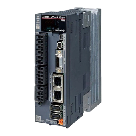
Model name 2F‐YZ581
Supported robot RH‐SDH series / RV‐SD series, RH‐SQH series / RV‐SQ series
RH‐F‐Dseries / RV‐F‐Dseries,RH‐F‐Qseries/RV‐F‐Qseries
CR750/CR751 series controller
CRn‐700 series controller
Encoder input 2 channel Only 1 channel available
Supported encoder Outputtype:Opencollectoroutput/Voltageoutput
/Linedriveroutput
Resolution(pulse/rotation) :max2000
(non‐compliant 4000,8000)
Operationcheckedencoder:E6B2‐CWZ1X‐2000(omron)
Supported encoder could be changed
with the shorting connector. Refer to
wiring diagram for detail.
Cable Type:Shieldedtwisted‐paircable
Conductorsize::Refer toWiringdirections
Cablelength:RefertoCommunicationspecifications
Output
channels
For robot controller 4 channels (in the case two encoders are connected)
8 channels (in the case one encoder is connected)
Enable to increase the number of
output channel by cascade.
For cascading 1 channel
Output type Line driver output
Power
supply
Input voltage 24Vdc(±10%)
Power consumption 500mA Depends on the encoder type.
Encoder supply Voltage: 5Vdc, Current: 160mA, 2 channel
Protection specification IP20
Ambient environment General environment Without inflammable gas or corrosive
gas
Ambient air temperature 0℃~40℃
Ambient humidity 45~85% Without dew drops
Mass Approx. 600 g
■Specifications
MitsubishiIndustrialRobot
EncoderDistributionUnit Manual
CR750/CR751seriescontroller
CRn‐700seriescontroller
■Introduction
Encoderdistributionunit2F‐YZ581isusedwhenonerotaryencoderisconnectedtomultiplerobotcontrollerswhen
thetrackingfunctionisused.Thedetailsof2F‐YZ581aredescribedinthissheet. Fordetailsofthetrackingfunction,
pleaserefertothe“Trackingfunctionmanual”attachedtotherobot.
Precautions
Donotusetheunitinexcessofratedvoltageoritcouldsufferdamage.
Wirethepowersupplycorrectlyoritcouldsufferdamage.
Wirethecableintheshortestpathinordertoavoidnoise.
Donotshortorgroundtheoutputsignal,oritcanbeburstordamaged.
Makesuretheunitisturnedoffwhenwiring,insertingorpullingoutoftheconnector,or
itcouldsufferdamage.
Donotdropthisunit.
Placethisunitonanevensurface,freefromvibration.
ENC1IN ENC1OUT1
Encoderdistributionunit
Encoder1
24V
(Powersupply)
ENC1CSC
Encoderdistributionunit
24V
(Powersupply)
Encoder2
Encoder1cascade
Encoder2cascade
Encoder1distribution
Encoder2distribution
ENC1OUT2
ENC1OUT3
ENC1OUT4
ENC2OUT1
ENC2OUT2
ENC2OUT3
ENC2OUT4
ENC2CSC
DC24
ENC2IN
Robotcontroller
Robotcontroller
Robotcontroller
Robotcontroller
Robotcontroller
Robotcontroller
Robotcontroller
Robotcontroller
ENC1IN ENC1OUT1
ENC1CSC
Encoder2distribution
ENC1OUT2
ENC1OUT3
ENC1OUT4
ENC2OUT1
ENC2OUT2
ENC2OUT3
ENC2OUT4
ENC2CSC
DC24
ENC2IN
Encoder1distribution
No. Encodertype Short‐connectorpoint
1Linedriveroutput MODE1
2Opencollectoroutput
Voltageoutput
MODE2
■Configurationdiagram
Theconnectionmethoddiffersaccordingtothenumberofencodersandrobotcontrollers.Connectinstrumentsby
referringtothefollowingexamplesofconfigurations.Pleasehavepowersupplyandencodersready.
Configurationexample1
Encoder :1unit
Robotcontroller :4units
Encoderdistributionunit :1unit
*Pleasedonotwiretheunusedterminalblocks.
ENC1IN ENC1OUT1
Encoderdistributionunit
Encoder1
24V
(Powersupply)
ENC1CSC
Encoder1cascade
Encoder1distribution
ENC1OUT2
ENC1OUT3
ENC1OUT4
ENC2OUT1
ENC2OUT2
ENC2OUT3
ENC2OUT4
ENC2CSC
DC24
ENC2IN
Robotcontroller
Robotcontroller
Robotcontroller
Robotcontroller
Encoderdistribution
Configurationexample3
Encoder :2units
Robotcontroller :4units
Encoderdistributionunit :1unit
ENC1IN ENC1OUT1
Encoderdistributionunit
Encoder1
24V
(Powersupply)
ENC1CSC
Encoder1cascade
Encoder1distribution
Encoder 2 distribution
ENC1OUT2
ENC1OUT3
ENC1OUT4
ENC2OUT1
ENC2OUT2
ENC2OUT3
ENC2OUT4
ENC2CSC
DC24
ENC2IN
Robotcontroller
Robotcontroller
Robotcontroller
Robotcontroller
Robotcontroller
Robotcontroller
Robotcontroller
Robotcontroller
Configurationexample2
Encoder :1unit(Linedriveroutputencoderonly)
Robotcontroller :8units
Encoderdistributionunit :1unit
*Pleasedonotwiretheunusedterminalblocks.
Connectionbetween
ENC1CSCandENC2IN
isneeded
*Pleasedonotwiretheunusedterminalblocks.
Connectionbetween
Encoderdistributionunits
isneeded.
ConnectionbetweenEncoderdistributionunitsisneededto
connecttheencodertomorethanfiverobotcontrollers. Referto
thewiringdiagramandtheenclosedareabelow .
Connectionforcascade
BFP‐A3300
BFP‐A3300
Powersupply 0V
+24V
B
B
DC24
ENC1IN/
ENC2IN
Z
Z
ENC1OUT1‐ENC1OUT4/
ENC2OUT1‐ENC2OUT4
B
B
Z
Z
ENC1CSC / ENC2CSC
B
B
Z
Z
GND
GND
GND
GND
V5
GND
GND
SLD
Robotcontroller
Encodertype:Linedriveroutput(MODE1)
Line driveroutput
MODE1
MODE2
Short‐connector
Encoderdistributionunit
Encoderdistributionunit
ENC1IN/ENC2IN
Encoder1 /Encoder2
B
B
Z
Z
V5
0V
0V
0V
‐
+
B
B
Z
Z
0V
0V
B
B
Z
Z
0V
0V
Powersupply 0V
24V
B
DC24
ENC1IN/
ENC2IN
Z
ENC1OUT1‐ENC1OUT4/
ENC2OUT1‐ENC2OUT4
B
B
Z
Z
ENC1CSC / ENC2CSC
B
B
Z
Z
GND
GND
GND
GND
V5
GND
GND
SLD
Robotcontroller
Voltageoutput
Opencollectoroutput
Encodertype:Opencollectoroutput/Voltageoutput(MODE2)
MODE1
MODE2
Short‐connector
Encoderdistributionunit
Encoderdistributionunit
ENC1IN/ENC2IN
Encoder1 / Encoder2
B
B
Z
Z
0V
0V
B
B
Z
Z
0V
0V
‐
+
B
B
Z
Z
V5
0V
0V
0V


