manuals.online logo
Brands
  1. Home
  2. •
  3. Brands
  4. •
  5. Mitsubishi Electric
  6. •
  7. Heating System
  8. •
  9. Mitsubishi Electric Ecodan PAC-TH011HT-E User manual

Mitsubishi Electric Ecodan PAC-TH011HT-E User manual

PARTS NAME : HIGH TEMP. THERMISTOR
PARTS No. : PAC-TH011HT-E <G>
SALES MODEL CODE : 7H1THR2G
WARNING
●
●
●
●
●
●
INSTALLATION MANUAL
● Before starting installation, read the following description together with the installation manual included with the unit.
● Please read carefully and observe fully the following safety precautions.
Precautions that must be observed to prevent injuries or death.
WARNING
After installation carry out a test run to ensure correct operation, then explain operation method and safety precautions to the
end user.
Tell your customers to keep this installation manual together with the operation manual, and when they give or sell this
machine to any other person include this installation manual and operation manual with it.
Before installing any accessories on the unit ensure the unit is isolated from the power supply.
Connections must be made securely and without tension on the terminals.
All electrical work should be performed by a qualified technician according to local regulations and the instructions given
in this manual.
The flow temperature from boiler MUST NOT exceed 70 °C (*1).
Before running Floor Dry-up function, disconnect IN4 and IN5 wirings. (*2)
*1 When the temperature sensed by flow temp. thermistor or return temp. thermistor exceeds 80°C, FTC4 will detect it as overheat error.
*2 High-temperature water produced by boiler operation could flow in and this could cause a big damage to the floor.
Make sure to install the boiler that has overheat protection and output flow temperature control.
●
BH79T377H02
CNP1(WHT)
TBI.1
CNV1
(WHT)
FT C 4
TBO.2
TBO.1
1
3
1
5
1
3
1
5
SW3
1
8
1
6
1
2
3
4
5
6
7
8
9
10
11
12
13
14
1
2
3
4
5
6
7
8
9
10
11
12
13
14
1
5
CN01
(BLK)
1
3
CN3C
(BLU)
CNBH
(WHT)
1
7
CNBC
 (GLY)
1
3
CNBHT
 (BLK)
1
3
CNIH
 (ORN)
1
2
CN22
2 4 6 8 10 12 14
1 3 5 7 9 10 13
2 4 6 8 10 12 14
1 3 5 7 9 10 13
(BLU)
CN2F
(YLW)
1
3
CN20
(RED)
CN21
(YLW)
1
3
CNW12
(RED)
CNW5
(WHT)
1
2
1
4
1
2
TBI.2
LED1
LED2
CNPWM
(WHT)
1
3
SW2
1
8
SW1
1
8
SW4
CN108
CNRF
(WHT)
LED4
LED3
1
5
CN105
(RED)
Item Piece
1Boiler ow temp. thermistor (THWB1) 5 m,
color: gray 1
2Boiler return temp. thermistor (THWB2) 5 m,
color: black 1
3Installation manual 1
<Included items>
<Connecting boiler thermistor>
1 2 3
Heat source
Heating
DHW
Heat pump
Boiler —
a) Heating room temperature ( )
FTC4
Boiler
Outdoor unit
b) Heating ow temperature ( )
c) Heating compensation curve ( )
FTC4
Boiler
Outdoor unit
Wireless remote
controller (option)
or
Room temperature
thermistor (option)
or
Main controller (remote
position)
Room thermostat (eld
supply)
or
Wireless remote controller *
(option)
Room thermostat
* Wireless remote controller can be changed to room thermostat.
1.2 Pipe work
(a) Boiler and heat pump are connected in parallel.
(b) Install a mixing tank (eld supply).
(c) Put 2 thermistors in boiler circuit. (THWB1: Flow temp., THWB2: Return temp.)
* It is recommended to protect the thermistors with heat insulating materials so as not to be affected by ambient temperature.
Note: These lead wires of the thermistors must avoid being in contact with pipe surfaces.
Boiler
Heating
Mixing tank
(field supply)
Cylinder unit/
Hydrobox
Outdoor unit
1
2
3
4
5
6
Boiler
Heating
Mixing tank
(field supply)
Hydrobox
DHW tank
Outdoor unit
1
2
7
8
9
3
4
5
6
Number Component
1Boiler ow temp. thermistor (THWB1)
2Boiler return temp. thermistor (THWB2)
3Flow temp. thermistor (THW6) (option)
4Return temp. thermistor (THW7) (option)
5 Circulation pump (eld supply)
6 Flow switch (eld supply) *1
*1 For safety protection, it is recommended to install a ow switch.
Number Component
1Boiler ow temp. thermistor (THWB1)
2Boiler return temp. thermistor (THWB2)
3Flow temp. thermistor (THW6) (option)
4Return temp. thermistor (THW7) (option)
5 Circulation pump (eld supply)
6 Flow switch (eld supply) *1
7Tank water temp. (THW5)
8Immersion heater (eld supply)
93-way valve (eld supply) *2
*1 For safety protection, it is recommended to install a ow switch.
*2 The use of two 2-way valves can perform the same function as a 3-way valve.
1. System
1) Heat source can be switched between heat pump and boiler by external input from power supplier or outdoor temperature thermistor.
2) Heat source can be switched according to running cost, CO2 emission, or outdoor temp.
3) In case of outdoor unit failure, backup operation is possible with boiler. *1
*1 When Hybrid is selected as heat source.
When Dip SW2-5 (Automatic switch to backup heat source operation) is set to ON.
Note: FTC4 can control boiler only in space heating mode.
1.1 Room thermostat connection
IMPORTANT NOTE
Be sure to connect room thermostat to FTC4.
When boiler is running, the heating operation is regulated by the room thermostat connected to FTC4.
Room thermostat
12345 6 7 8 9 10 11 12 13 14
TBI.2
THWB1 THWB2
1
Screw positions
6
Place the terminal
blocks so that the
orientations of the
labels are correct.
BH79T377H02
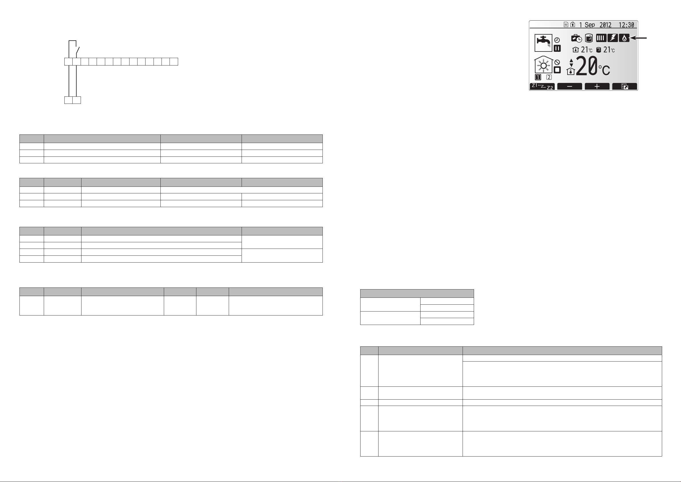
2. Setting the Main Controller
<Main screen icons>
When boiler is running, icon 1 is displayed.
<Service menu>
(1) Heat source setting
Select heat sources to run.
[Standard] *1
• Heat pump and Electric heater
[Heater] *1
• Electric heater only
[Boiler]
• Boiler only (for emergency operation)
Note: DHW mode is NOT available in this setting.
[Hybrid]*1
• Standard (Heat pump and Electric heater) and Boiler
• Switch between heat sources dependent on energy saving calculation (running cost/CO2 emission) or outdoor ambient tempera-
ture. *2
*1 FTC4 can switch heat source to Boiler by external signal when Boiler is selected in “External input settings”.
*2 Make detailed settings in "Boiler settings" of "Operation settings ".
(2) Operation settings → Boiler settings
• Select prioritised items in energy saving calculation.
[Hybrid settings]
(a) Outdoor ambient temperature
Set the ambient temperature to switch to Boiler operation.
(b) Priority mode
Ambient: Heat source is switched based on outdoor ambient temperature.
Cost: Heat source is switched based on running cost or outdoor ambient temperature.
CO2: Heat source is switched based on CO2 emission or outdoor ambient temperature.
[Intelligent settings]
Set parameters for energy saving calculation.
The following settings will be applied when "Cost" or "CO2" is selected in Priority mode.
(c) Energy price
Enter unit prices of electricity, and gas or oil (depending on boiler type) per 1 kWh.
(d) CO2emission
Enter CO2 emission amount from electricity or boiler (gas or oil).
(e) Heat source
Enter outdoor unit capacity, electric heater capacity, and boiler efciency.
(3) External input settings
• Select which heat source to run when IN4 or IN5 external input signal is received.
• If Boiler is selected, boiler will start running by receiving external input signals.
External input settings
Demand control (IN4) Boiler
Heat source OFF
Outdoor thermostat (IN5) Boiler
Heater
3. Error codes
Code Error Action
LC Boiler circulation water temperature
overheat protection
Check if the setting temperature of the Boiler for heating exceeds the restriction.
Flow rate of the heating circuit from the boiler may be reduced. Check for
water leakage
strainer blockage
water circulation pump function
•
•
•
LD Boiler temperature thermistor
(THWB1, THWB2) failure
Re-attach any thermistors that have become dislodged. Check resistance across the
thermistor.
LE Boiler operation error Re-attach any thermistors that have become dislodged. Check the status of the boiler.
LH Boiler circulation water freeze
protection
Flow rate of the heating circuit from the boiler may be reduced. Check for
water leakage
strainer blockage
water circulation pump function
•
•
•
LL Setting errors of Dip switches on
FTC4 control board
For boiler operation, check that Dip SW1-1 is set to ON (With Boiler) and Dip SW2-6
is set to ON (With Mixing Tank).
For 2-zone temperature control, check Dip SW2-7 is set to ON (2-zone) and Dip
SW2-6 is set to ON (With Mixing Tank).
1.3 Wiring for boiler control
Connect OUT10 to boiler external input (room thermostat).
1.4 Dip switch functions
Set Dip SW1-1 and SW2-6 to ON .
Dip switch
Function OFF ON
SW1-1 Boiler WITHOUT Boiler WITH Boiler
SW2-5 Automatic switch to backup heater only operation Inactive Active
SW2-6 Mixing tank WITHOUT Mixing tank WITH Mixing tank
<Signal inputs>
When connecting room thermostat (eld supply), wire the cable to IN1.
Name
Terminal block
Item OFF (Open) ON (Short)
IN1 TBI.1 1-2 Room thermostat 1 input Refer to SW2-1.
IN4 TBI.1 7-8 Demand control input Normal Heat source OFF/Boiler operation
IN5 TBI.1 9-10 Outdoor thermostat input Standard operation Heat operation/Boiler operation
<Thermistor inputs>
For details on where to install the thermistors, refer to chapter “1.2 Pipe work” in this manual.
Name
Terminal block
Item Optional part model
THW6 TBI.2 7-8 Zone 1 ow water temp. thermistor (Option) PAC-TH011-E
THW7 TBI.2 9-10 Zone 1 return water temp. thermistor (Option)
THWB1 TBI.2 3-4 Boiler ow water temp. thermistor —
THWB2 TBI.2 5-6 Boiler return water temp. thermistor
<Outputs>
Connect OUT10 to boiler external input (Room thermostat).
Name
Terminal block
Item OFF ON Signal/Max current
OUT10 TBO.1 1-2 Boiler output OFF ON
non-voltage contact
• 220 - 240V AC (30V DC) 0.5 A or less
• 10 mA 5V DC or more
Note:
• OUT10 is separated by basic insulation from other external output signals in FTC4.
• Connect the surge absorber according to the load at site.
• When the wires are wired to adjacent terminals , use ring terminals and insulate the wires.
• Do not splice the wiring to extend or shorten it, or this could affect correct monitoring of each temperature.
If the wiring is too long, bundle it with a strap to adjust the length.
(External input)
Room thermostat
1
1 2 3 4 567 8 9 10 11 12 13 14
FTC4 (OUT10)
TBO.1 1-2
Boiler
Non-voltage contact
• 220 - 240V AC (30V DC) 0.5 A or less
• 10 mA 5V DC or more
Related Links Model Number: PAC-TH011HT-E
Ecodan PAC-TH011HT-E Installation Manual (BH79T377H02)

Other Mitsubishi Electric Heating System manuals

Mitsubishi Electric City Multi R2 Series User manual

Mitsubishi Electric

Mitsubishi Electric City Multi R2 Series User manual

Mitsubishi Electric Ecodan HUS210FTC4ST User manual

Mitsubishi Electric

Mitsubishi Electric Ecodan HUS210FTC4ST User manual

Mitsubishi Electric VL-250CZPVU-R-E User manual

Mitsubishi Electric

Mitsubishi Electric VL-250CZPVU-R-E User manual

Mitsubishi Electric LGH-50RVS-E User manual

Mitsubishi Electric

Mitsubishi Electric LGH-50RVS-E User manual

Mitsubishi Electric Ecodan FTC4 User manual

Mitsubishi Electric

Mitsubishi Electric Ecodan FTC4 User manual

Mitsubishi Electric FTC5 User manual

Mitsubishi Electric

Mitsubishi Electric FTC5 User manual

Mitsubishi Electric VL-250CZPVU Series User manual

Mitsubishi Electric

Mitsubishi Electric VL-250CZPVU Series User manual

Mitsubishi Electric VL-250CZPVU-R-E User manual

Mitsubishi Electric

Mitsubishi Electric VL-250CZPVU-R-E User manual

Mitsubishi Electric Ecodan PAR-WT50R-E User manual

Mitsubishi Electric

Mitsubishi Electric Ecodan PAR-WT50R-E User manual

Mitsubishi Electric ecodan EHPT20Q-VM2EA User manual

Mitsubishi Electric

Mitsubishi Electric ecodan EHPT20Q-VM2EA User manual

Mitsubishi Electric Ecodan User manual

Mitsubishi Electric

Mitsubishi Electric Ecodan User manual

Mitsubishi Electric VL-350CZPVU-R-E User manual

Mitsubishi Electric

Mitsubishi Electric VL-350CZPVU-R-E User manual

Mitsubishi Electric PZ-61DR-E User manual

Mitsubishi Electric

Mitsubishi Electric PZ-61DR-E User manual

Mitsubishi Electric ecodan EHPT20Q-VM2EA User manual

Mitsubishi Electric

Mitsubishi Electric ecodan EHPT20Q-VM2EA User manual

Mitsubishi Electric EHSC-VM6A User manual

Mitsubishi Electric

Mitsubishi Electric EHSC-VM6A User manual

Mitsubishi Electric Ecodan EHSC-VM6D-CN User manual

Mitsubishi Electric

Mitsubishi Electric Ecodan EHSC-VM6D-CN User manual

Popular Heating System manuals by other brands

SIC CFR micro E Series Installation, use and maintenance manual

SIC

SIC CFR micro E Series Installation, use and maintenance manual

nVent RAYCHEM JBM-100-E manual

nVent RAYCHEM

nVent RAYCHEM JBM-100-E manual

Viessmann Divicon installation instructions

Viessmann

Viessmann Divicon installation instructions

BENIFERRO ZPTX0010-P manual

BENIFERRO

BENIFERRO ZPTX0010-P manual

Bard W24G4 installation instructions

Bard

Bard W24G4 installation instructions

Sabiana Carisma Floor CRP-ECM installation instructions

Sabiana

Sabiana Carisma Floor CRP-ECM installation instructions

Toyostove Laser 30 Installation and operation instruction

Toyostove

Toyostove Laser 30 Installation and operation instruction

Legalett 4000E manual

Legalett

Legalett 4000E manual

thermital TSOL CN 150/1 S BLU 30 Installer, technical assistance centre and user manual

thermital

thermital TSOL CN 150/1 S BLU 30 Installer, technical assistance centre and user manual

Viessmann VITOCELL 300B Service instructions for contractors

Viessmann

Viessmann VITOCELL 300B Service instructions for contractors

Salda RIS 2500HW EKO 3.0 Technical manual

Salda

Salda RIS 2500HW EKO 3.0 Technical manual

Ideal Clima KERS 50 EVO User's and installer's manual

Ideal Clima

Ideal Clima KERS 50 EVO User's and installer's manual

Haier HACI-RP Series Instructions for installation, use and maintenance manual

Haier

Haier HACI-RP Series Instructions for installation, use and maintenance manual

Xvent XHOUSE-300 Installation and operation manual

Xvent

Xvent XHOUSE-300 Installation and operation manual

Master BV 77E Technical data

Master

Master BV 77E Technical data

Brink Renovent Excellent 300 installation instructions

Brink

Brink Renovent Excellent 300 installation instructions

Midea CE-HRV-800 Owners manual and installation manual

Midea

Midea CE-HRV-800 Owners manual and installation manual

Oxygen TYPHON 2000 manual

Oxygen

Oxygen TYPHON 2000 manual

manuals.online logo
manuals.online logoBrands
  • About & Mission
  • Contact us
  • Privacy Policy
  • Terms and Conditions

Copyright 2025 Manuals.Online. All Rights Reserved.