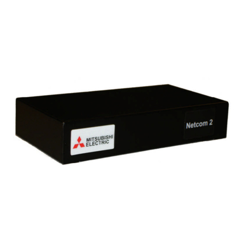
Mitsubishi Electric Netcom 2 User manual

SVA026 Netcom 2 User Manual ver5 1
Mitsubishi
Netcom 2
User Manual
Version 5.1

SVA026 Netcom 2 User Manual ver5 2
TableofContents
1. What is a Netcom?.......................................................................................................... 3
2. Who do I Contact For Technical Support? ..................................................................... 3
3. What are the System Requirements for Netcom? ........................................................... 3
3.1 Operating System Requirements................................................................................... 3
3.2 UPSMAN WINDOWS Solution: ................................................................................. 4
3.3 UPSMAN UNIX Solution: ........................................................................................... 4
3.4 APPLE MAC X Solution:............................................................................................. 4
3.5 UNMS II Solution :....................................................................................................... 4
3.6 RCCMD Solution (shut downs):................................................................................... 4
3.7 No longer supported UPSMAN versions (please choose RCCMD instead) : .............. 6
3.8 Web Browser Requirements ......................................................................................... 6
3.9 Special Requirements for Web Browsers ..................................................................... 6
3.10 Special Requirements for Firewall Access ................................................................. 6
4. How do I Configure the Netcom?................................................................................... 7
4.1 Installing the Netcom Utilities...................................................................................... 7
4.2 Configuring the Netcom ............................................................................................... 7
4.2.1 HyperTerminal Setup example (serial cable) ............................................................ 7
4.2.2 Configuring the IP address with Window XP............................................................ 8
4.2.3 Configuring the IP address with Windows 7 ........................................................... 13
5. How do I Update the Netcom Firmware?..................................................................... 17
6. Netcom Web Server...................................................................................................... 19
7.1 Login Page .................................................................................................................. 20
7.2 UPS Status Page/ UPS/ Overview .............................................................................. 21
7.3 Identification/UPS Identification Page ....................................................................... 23
7.4 Variables/Variables Page ............................................................................................ 24
7.5 Event Log/View Events Page ..................................................................................... 25
7.6 Agent Setup/UPS/Configuration Page........................................................................ 26
7.7 Nominal Values/UPS Nominal Values Page .............................................................. 27
7.8 Nominal Values/UPS Nominal Values Setup............................................................. 28
7.9 Shutdown/UPS Shutdown Setup Page........................................................................ 29
7.11Overview/Network Setup Page.................................................................................. 32
7.12 IP Config/Setup/IP Configuration Page.................................................................... 33
7.13 HTTP/HTTP Setup Page .......................................................................................... 34
7.14 LDAP Servers/Setup/LDAP Servers Page................................................................ 35
7.15 SNMP NMS/Setup SNMP Page ............................................................................... 36
7.16 SNMP Rec’rs/SNMP Receivers Page....................................................................... 37
7.17 Event Notification/Event Notification ...................................................................... 38
7.19 Users/Setup/Users ..................................................................................................... 43
7.20 Email Alerts/ Setup/ Email Alerts............................................................................. 44
7.21 Time Setting/ Setup/ Time Settings .......................................................................... 45
7.22 Syslog Servers/ Setup/ Syslog Servers ..................................................................... 46
7.23 Events/ View/ Events................................................................................................ 47
SVA026 Netcom 2 User Manual ver5 3
7.24 Preferences/ Preferences Page .................................................................................. 48
7.25 Restart/Restart Page .................................................................................................. 49
APPENDIX A RJ45 to DB9 pin out................................................................................. 50
APPENDIX B 9700 and 2033A connection..................................................................... 51
APPENDIX C SEC connections....................................................................................... 52
APPENDIX D MIBS ........................................................................................................ 53
1.WhatisaNetcom?
A Netcom is a standalone UPS peripheral used for UPS monitoring, event
management, SNMP interfacing, and critical event notification. It consists of a small
computer with a serial interface for connecting to and communicating with a UPS, and an
Ethernet interface for connecting to your local network. The Netcom has its own
embedded web server to allow you to monitor the status of the UPS using a Web
browser. Event management is also configured and performed on the Web Server. It
supports the Simple Network Management Protocol (SNMP) for integration with a
Network Management System and Telnet for configuration.
You can configure the Netcom to perform appropriate actions when an event is
detected including email and remote computer shutdown. The optional Remote
shutdown agent runs on one or more remote computers and communicates with the
Netcom to allow remote shutdown of up to 500 computers powered by the UPS.
2.Whodo IContactForTechnicalSupport?
Contact the Technical
Support group for help configuring and using Netcom or any Mitsubishi UPS product
Phone 724-778-5111
Fax 724-778-3146
3.WhataretheSystemRequirementsforNetcom?
The Netcom runs as a standalone unit. It includes a 120-volt AC power source
plug, and a DE9 to RJ45 communications cable for connecting to the UPS. A standard
network cable for connecting to the local Ethernet network must be provided. The 9900,
2033G and 9800AE UPS have an optional internal power supply that can be purchased,
please contact your local Sales Representative for more details.
3.1 Operating System Requirements
Installation procedure for the shut down codes are located on the CD provided with the
Netcom in a file named “Shut Down Manual”. The user will need a copy of their sales
order for the serial number of each shut down code.

SVA026 Netcom 2 User Manual ver5 4
The remote shutdown agents will run on the following operating systems:
3.2UPSMANWINDOWSSolution:
WINDOWS 7 (Professional or higher) x86/x64 CPU
WINDOWS Server 2008 CORE x64 CPU
WINDOWS Server 2008 R 2 (Standard, Enterprise, Datacenter, Webserver) x64
CPU
WINDOWS Server 2008 (Standard, Enterprise, Datacenter, Webserver) x64 CPU
(Standard, Enterprise, Datacenter, Webserver)
WINDOWS VISTA (Business or higher) x86/x64 CPU
WINDOWS 2003 Server X86/X64 CPU
WINDOWS XP (Professional or higher) x86/x64 CPU
WINDOWS 2000 Server
WINDOWS 2000 SP4 x86 CPU
3.3UPSMANUNIXSolution:
SUN SOLARIS 8, 9, 10, 11 X86, X64 X32 & X64 & SPARC CPU
IBM AIX V. 5.3 RS 6000 RISC and PowerPC CPU
HP UNIX V 10.20, 11.0-11i HP PA-RISC CPU (not Itanium - only RCCMD !)
LINUX X86 - all X86/x64 CPU based LINUX versions, eg. United 1.x /SCO
Linux
Server 4, LINUX SUSE 7-10.x & SLES, Fedora Linux, GENTOO Linux, RedHat
7.0-
9.0, RH 4, RH5.4x x32/x64, TurboLinux 6.1-6.5, 7.x, Debian 4-5.x, Caldera Open
Linux 2.3, Open Linux 3.1.x, Ubuntu, CentOS X86/x64 and all other x86/x64
kernel 2 based LINUX, NOVELL OES-Linux
3.4APPLEMACXSolution:
MAC OS X 10.4x, 10.5x Leopard, 10.6 Snow Leopard
3.5UNMSIISolution:
WINDOWS XP from Service Pack 2, WINDOWS Server 2003 SP2
Multiple network shutdowns
An RCCMD installation keycode opens access to RCCMD clients for all OS
mentioned above.
3.6RCCMDSolution(shutdow n s ) :

SVA026 Netcom 2 User Manual ver5 5
Additional to the above listed OS, the following listed RCCMD versions are
available
From Mitsubishi. Please contact Mitsubishi for the following;
VMWARE Sphere ESX 4 i
VMWARE ESX Server 3.5x / 4 (VMWare certified)
CITRIX XEN Server 4.5 and 5.5 and higher (Citrix certified)
MICROSOFT HYPER-V 2008
CENTOS INTEL x86, x64 & IA64 CPU
LINUX PowerPC CPU
LINUX ITANIUM X64 CPU
LINUX SUSE 6.3x APX ALPHA CPU
HP UNIX 9 PA-RISC CPU
HP UNIX V 11.2x, 11.3x SPARC & ITANIUM 64 CPU
QNX 4 and QNX 6 on X86
MAC OS X 10.1-10.3
APPLE MAC OS 9.x or higher
NOVELL NetWare 3.10, 3.11, 3.20 ,4.10-4.20, 5.0, 5.1, 6.0, 6.1, 6.5
IBM OS/2 Version WARP 3.0, 4.0, LAN SERVER 3.0, 4.0, 5.0 X86 CPU
IBM AIX V. 3.25, 4.1, 4.3, 5.1, 5.2, 5.3 RS 6000 RISC and PowerPC CPU
IBM AIX V. 6 on PowerPC4, 970, Power5, Power 6 CPU
IBM AIX L (Linux) V. 6 on Power 6 CPU
SIEMENS SINIX 5.41 MX 300 Z X86 CPU
SCO OpenServer 5.x u. 6.x 4 X86 CPU
SILICON GRAPHICS IRIX V. 6.5x RISC MIPS CPU
WINDOWS 2008 X86/X64 Virtualserver HYPERVISOR
WINDOWS 2003 Server ITANIUM 64 CPU
WINDOWS 2000 SP4 x86 CPU
WINDOWS NT 4 SVP 6
WINDOWS NT 3.51 and NT 4 SVP3-6a X86 CPU
WINDOWS NT 3.51 ALPHA CPU
WINDOWS NT 3.15 MIPS CPU
WINDOWS 98SE & ME X86 CPU
DEC UNIX SVR 3 OSF/1 ALPHA CPU
DATA GENERAL UNIX X 86 CPU
DATA GENERAL UNIX MOTOROLA M88 CPU
MOTOROLA UNIX M88 CPU
SUN SOLARIS 7 (5.7) SPARC CPU
SUN OS 4 SPARC CPU
UNIXWARE 2, 7 on X86 CPU, UNIXWARE 7.x SVR 4 compatible X86 CPU
INTERACTIVE UNIX 3.2 X86 CPU
SIEMENS SINIX 5.41 – 5.45, RELIANT UNIX 5.45x RM RISC
HP/COMPAQ TRU64 V 5.x ALPHA CPU, Digital UNIX V 4.0-5.1 ALPHA CPU
FREE BSD UNIX SVR 4 X86 V 4.4x and 6.x

SVA026 Netcom 2 User Manual ver5 6
3.7Nolo n g e r supportedUPSMANversions(pleasechoose
RCCMDinstead):
DEC ULTRIX, HP UNIX 9 PA-RISC CPU, IBM
OS/2 Version WARP 4.0 X86 CPU, IBM OS/2
Version LAN SERVER 3.0, 4.0, 5.0 INTEL CPU,
IBM OS/2 SNMP sub-agent, IBM AIX V 3.25, IBM
AIX 4.1, WINDOWS NT 3.51 INTEL CPU,
WINDOWS NT 3.51 ALPHA CPU, NOVELL
NetWare 3.11 and 3.12 INTEL CPU,
INTERACTIVE UNIX 3.2, VMS 5.5 for VAX or
ALPHA, SUN SOLARIS 2.5, LINUX SUSE 5.x and
6.x. WINDOWS NT 4.0 ALPHA CPU, DEC
OPEN VMS on VAX CPU, V.5x, V.6x, V. 7x -
UPSMAN V3, DEC OPEN VMS on ALPHA AXP
CPU V.6x; APPLE MAC OS 9.4, DEC OPEN VMS
on ALPHA CPU V 7.x, SIEMENS SINIX 5.41 –
5.45, RELIANT UNIX 5.45x RM RISC
HP/COMPAQ TRUE 64 V 5.x ALPHA CPU,
Digital UNIX V 4.0-5.1 ALPHA CPU,
3.8 Web Browser Requirements
Supported web browsers include:
Internet Explorer 6.0 or higher
The Netcom requires Macromedia Flash 6.0 or higher.
3.9 Special Requirements for Web Browsers
In some instances, the caching on a Web Browser can cause the current page not
to be updated while navigating on the Netcom user interface. For example, while viewing
the Event Log Page you might click on the Variables menu option but still see the Event
Log page. If this happens, follow the steps to correctly configure the caching for your
Web Browser to reload each page upon each visit. Below is the example procedure for
Internet Explorer v6:
Open Internet Explorer and select the Tools menu option.
Select the Internet Options submenu.
Under the Temporary Internet files section, click the Settings button.
Click the Every visit to the page radio button.
Click the OK button.
Close the Internet Options dialog box.
3.10 Special Requirements for Firewall Access
Firewalls installed on the network must allow for the Netcom communication.
Ensure that the web server port and all SNMP ports are allowed. When Windows XP

SVA026 Netcom 2 User Manual ver5 7
Service Pack 2 is installed on a computer it will turn on the personal firewall. Below are
the steps to open up the web port for Netcom in Windows XP Firewall:
Select Start Menu > Control Panel.
Select Network Connections and right click on the connection that is
being used.
Click on Properties and click the Advanced tab in the Properties
dialogue.
Press the Settings... button to bring up the Firewall dialogue.
Go to the Exceptions tab and click the Add Port button.
For Name enter Netcom Web Port and for Port Number enter 80. Press the OK
button.
You now will be able to access the Netcom web port through the Windows XP
Firewall.
4.Howdo IConfiguretheNetcom?
4.1InstallingtheNetcomUtilities
The Netcom CD contains the following:
SNMP MIB
Netcom User Manual (PDF)
Shut down installation procedure
Netcom FAQ
Firmware
To install the Netcom Utilities or access any of the documents, place the Netcom CD in
the CD
drive. The Netcom Utilities CD should automatically start. Follow the instructions
provided on
your screen.
4.2 Configuring the Netcom
The initial network settings can be made by connecting the Netcom to a serial
communication program using the included configuration cable or cross over cable and
laptop.
4.2.1 HyperTerminal Setup example (serial cable)
1. Connect the 9 pin connector to the PC and the 9 pin receptacle labeled “Serial
RS232” on the Netcom.

SVA026 Netcom 2 User Manual ver5 8
2. Open a HyperTerminal session by selecting (Installed location may vary)
Start > All Programs > Accessories > Communications > HyperTerminal.
3. Select an available communications port from the drop-down list.
4. Select the following port settings:
Bits per second: 19200
Data bits: 8
Parity: None
Stop bits: 1
Flow Control: None
5. Cycle power from the Netcom by pulling out the power connector and
reinserting.
6. Wait for >and type test, this must be done within five seconds. This will
disable the time out function and allow the IP address to be changed.
7. Type setup and enter.
8. The default IP address, IP mask, and IP gateway will be displayed.
9. Enter your IP address and press enter.
10. Enter your sub net mask and press enter.
11. Enter your IP gateway and press enter.
12. After the IP gateway is entered it will ask to save the changes, enter y.
13. When connecting to a 9700 or 2033A the protocol must be change, this is
accomplished by typing “ups m”. After entering ups m the user will see
“Mitsubishi protocol selected”, the user must type in “commit” to save the
change.
14. System will now reboot and is ready for Internet connectivity.
4.2.2ConfiguringtheIPaddresswithWindowXP.
1. Connect the cross over cable provided with the Netcom2 to your PC and the
“Network” RJ45 port of the Netcom2.
2. Plug in the power supply included in the Netcom2 box to the +12VDC.

SVA026 Netcom 2 User Manual ver5 9
3. On the PC that the cross over cable is connected to, select ,“Control
Panel”, “Network Connections”. Right click on “Local Area Connection” and
select “Properties”.
4. Double click “Internet Protocol (TCP/IP)”.

SVA026 Netcom 2 User Manual ver5 10
5. Select “Use the Following IP address:”
6. Enter; IP address: 192.168.0.1
Subnet mask: 255.255.255.0
Default gateway: 192.168.0.253

SVA026 Netcom 2 User Manual ver5 11
7. Click on the “Internet Protocol (TCP/IP) Properties” screen.
8. Click on the “Local Area Connection Properties” screen.
9. Click on .
10. Select .
11. Enter: http://192.168.0.253,
and click OK.
12. The Netcom2 log in screen will appear.

SVA026 Netcom 2 User Manual ver5 12
13. If the Netcom log in screen does not appear perform the following;
a. Verify the cross over cable is connected to the Netcom2 port labeled
“Network”
b. Verify the power light on the Netcom2 is green and the status light is blinking.
c. Ping the entered IP address in the DOS prompt.
d. Verify the “local area connection” is connected in the Network connections
screen
14. The default login and password of a Netcom is;
Username: admin
Password: admin
15. From the home screen of the Netcom2 select “IP config”.
16. The user will be able to change the IP information from this screen. After the IP
information has been entered the “Save” button must be selected for the
information to be saved.

SVA026 Netcom 2 User Manual ver5 13
17. Once the “Save” button is selected you will be presented with the following
screen. Selecting OK will write the IP address to the memory of the Netcom. You
will no longer be able to communicate with the Netcom at the default IP address.
**If the Netcom2 is going to be connected to a 2033A or 9700 the protocol will have to
be changed using the DB9 connector supplied with the Netcom2. Please refer to
the step 4.2.1.
4.2.3ConfiguringtheIPaddresswithWindows7
1. Connect the cross over cable provided with the Netcom2 to your PC and
the RJ45 port labeled “Network” on the Netcom2.
2. Plug the power supply included with the Netcom2 into a wall outlet and the port
labeled +12VDC.
3. On the PC that the cross over cable is connected to the Netcom, select , and
in the “Search programs and files” type in “Control Panel”.

SVA026 Netcom 2 User Manual ver5 14
4. Select Control Panel.
5. Under “Network and Internet” select “view network and status tasks”.
6. In the “Network and sharing center” double click on the “local Area Connection”.
7. In the “local Area Connection Status” select .
8. Double click on .
9. Select the “Use the Following IP address” radio button.
10. Enter the following information;
IP Address: 192.168.0.1
Subnet Masks: 255.255.255.0
Default gateway: 192.168.0.253

SVA026 Netcom 2 User Manual ver5 15
11. Click ok.
12. Click ok, on the Local Area Connection Properties.
13. Select , in the “Search programs and files” enter “run”.
14. Select run.
15. Enter: http://192.168.0.253
16. If the Netcom log in screen is present skip to step 17, if the screen does not appear
perform the following;
e. Verify the cross over cable is connected to the Netcom2 port labeled
“Network”
f. Verify the power light on the Netcom2 is green and the status light is blinking.
g. Ping the entered IP address in the DOS prompt
h. Verify the “local area connection” is connected in the Network connections
screen
17. The default login and password of a Netcom is;
Username: admin
Password: admin
18. From the home screen of the Netcom2 select “IP config”

SVA026 Netcom 2 User Manual ver5 16
19. The user will be able to change the IP information from this screen. After the IP
information has been entered the “Save” button must be selected for the
information to be saved.
20. Once the “Save” button is selected you will be presented with the following
screen. Selecting OK will write the IP address to the memory of the Netcom. You
will no longer be able to communicate with the Netcom at the default IP address.
21. If the Netcom2 is going to be connected to a 2033A or 9700 the protocol will
have to be changed using the DB9 connector supplied with the Netcom2. Please
refer to the step XX.

SVA026 Netcom 2 User Manual ver5 17
5.Howdo IUpdatetheNetcomFirmware?
Configuration Upgrade.
The Netcom2 is shipped with firmware installed, if needed the latest firmware
version is available for download at;
www.meppi.com/Products/UninterruptiblePowerSupplies/Communication.
The firmware version installed in the Netcom2 can be found in the log in screen
under the user name and password.
5.1. Open “SineticaTFTPclient.exe” on the Netcom CD.
Figure 5.1

SVA026 Netcom 2 User Manual ver5 18
5.2. In the 'File Settings' group select 'APPLICATION UPGRADE' from the
'File Transfer Type' drop down list.
5.3. In the 'Download File Name' edit box select the name of the file,
XX.XX.X.bin, supplied on the Netcom 2 CD.
5.4. In the ‘TFTP Settings’ group enter the required IP address of the unit to be
upgraded in the ‘IP Address’ box.
5.5. Click the 'DOWNLOAD TO DEVICE' button. A blue task bar will flow from
left to right and data information will be displayed in the information box. When
“connection closed” appears the firmware installation will be complete.
5.6. The new configuration data will be written to the EEPROM in the Netcom2
unit
5.7. If the Netcom is going to be communicating with a 2033A or 9700 the
protocol will have to be selected. This is done in the HyperTerminal session in
section

SVA026 Netcom 2 User Manual ver5 19
6.NetcomWebServer
Before attempting to connect to the Netcom2 for the first time check the
following;
1. An IP address has been assigned
2. The supplied RJ45 to DB9 cable is connected to the port labeled UPS and
connected to the UPS communication port (contact Mitsubishi or your local service
group)
3. The intranet cable is connected to the Network plug and the amber and green
lights are flashing
4. Power is applied to the Netcom and the power and status lights are on.
5. The proper protocol has been selected; 9700 and 2033A UPS require MIT all
other require SEC.

SVA026 Netcom 2 User Manual ver5 20
7.1LoginPage
Figure 7
After connecting to the Netcom Figure 2 will be displayed, the default password
for the Netcom is:
Username: admin
Password: admin
The Netcom2 Firmware version is located under the Serial number; the most current
software version can be downloaded at Meppi.com.
The default password and login for the Netcom is admin, admin. If the password
is changed and lost the following steps will need to be completed to reset the password;
1. Establish a Hyper-terminal session as described in Section 4 of this manual.
2. Connect a terminal to the serial port.
3. Reboot the Netcom.
4. At the serial prompt enter “test” within 5s.
5. At the serial prompt enter “pwdrst”.
6. At the serial prompt enter “x”.
7. When the system starts (status indicator flashing at 4Hz) login using
“admin”/”admin”
8. Change and save system user configuration as needed.
9. Reboot
Table of contents
Other Mitsubishi Electric UPS manuals

Mitsubishi Electric
Mitsubishi Electric 9700 Series User manual

Mitsubishi Electric
Mitsubishi Electric 9900B Series User manual

Mitsubishi Electric
Mitsubishi Electric 2033D SERIES User manual

Mitsubishi Electric
Mitsubishi Electric 2033G Series User manual

Mitsubishi Electric
Mitsubishi Electric 9800A Series User manual

Mitsubishi Electric
Mitsubishi Electric 1100A Series User manual

Mitsubishi Electric
Mitsubishi Electric 9700 Series User manual

Mitsubishi Electric
Mitsubishi Electric Netcom 2 User manual

Mitsubishi Electric
Mitsubishi Electric 9800A Series User manual

Mitsubishi Electric
Mitsubishi Electric 1100B Series User manual