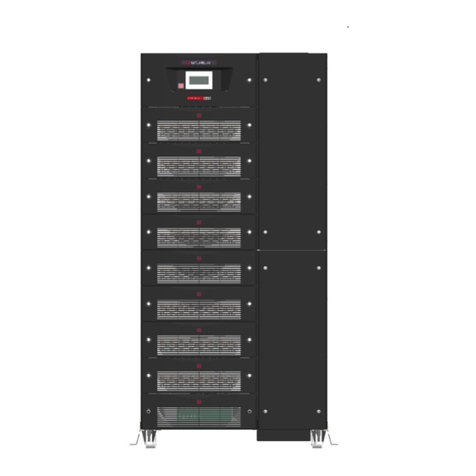
Mitsubishi Electric 9900B Series User manual

UNINTERRUPTIBLE POWER SUPPLY SYSTEM
MODEL
9900B SERIES
OWNER’S / TECHNICAL MANUAL
(Inclusive Parallel Operation System Application)

Preface
Revision 4 06/09/2020
U-ENM00030

MITSUBISHI ELECTRIC 9900B SERIES UPS
MITSUBISHI
ELECTRIC
9900B SERIES UPS
OWNERS / TECHNICAL MANUAL
Page Number:
i
TABLE OF CONTENTS
LIST OF TABLES ................................................................................................ ii
LIST OF FIGURES .............................................................................................. iii
HOW TO USE THIS MANUAL ............................................................................ iv
1.0 INTRODUCTION ........................................................................................ 1-1
1.1SAFETY PRECAUTION ............................................................................. 1-2
1.2GENERAL ................................................................................................... 1-6
1.3DEFINITIONS ............................................................................................. 1-7
1.4OPERATION OVERVIEW .......................................................................... 1-8
1.5SPECIFICATIONS ...................................................................................... 1-20
2.0 OPERATION CONTROLS AND INDICATORS ......................................... 2-1
2.1 LED DISPLAY ............................................................................................. 2-2
2.2 EPO BUTTON ............................................................................................. 2-2
2.3 LIQUID CRYSTAL DISPLAY ...................................................................... 2-3
2.4 EXTERNAL SIGNAL TERMINAL BLOCK .................................................. 2-9
2.5EXTERNAL COMMUNICATIONS................................................................ 2-15
3.0 INSTALLATION AND OPERATION .......................................................... 3-1
3.1 TRANSPORTATION AND INSTALLATION ............................................... 3-1
3.2 INSTALLATION PROCEDURE .................................................................. 3-1
3.3 PROCEDURE FOR CABLE CONNECTIONS ........................................... 3-2
3.4 OPERATING PROCEDURES .................................................................... 3-15
4.0 RESPONSE TO UPS FAILURE ................................................................. 4-1
5.0 PARTS REPLACEMENT ........................................................................... 5-1
6.0 FAULT CODES .......................................................................................... 6-1
7.0 WARRANTY & OUT OF WARRANTY SERVICE ..................................... 7-1
8.0 MAINTENANCE CONTRACTS .................................................................. 8-1
8.1 SERVICE OFFERINGS .............................................................................. 8-1
8.2 PACKAGES ................................................................................................ 8-1

MITSUBISHI ELECTRIC 9900B SERIES UPS
MITSUBISHI
ELECTRIC
9900B SERIES UPS
OWNERS / TECHNICAL MANUAL
Page Number:
ii
LISTOF TABLES
Table 1.1 UPS Installation and Operational Environment............................ 1-3
Table 1.2 Rating of Bypass Input Circuit Breaker ....................................... 1-5
Table 1.3 Power Specifications .................................................................... 1-20
Table 1.4 UPS Module Information............................................................... 1-20
Table 1.5 Detail of Specifications ................................................................. 1-21
Table 1.6 Rating of Contactors, Breakers and Fuses .................................. 1-22
Table 2.1 Selectable Output Contacts.......................................................... 2-12
Table 2.2 Selectable Input Contacts............................................................. 2-14
Table 3.1 How to Transport and Install the System ..................................... 3-1
Table 3.2 List of UPS Weights...................................................................... 3-1
Table 3.3 Maximum Permitted Fault Current................................................ 3-2
Table 3.4 Recommended Cable Sizes ......................................................... 3-5
Table 3.5 Recommended Hardware............................................................. 3-5
Table 3.6 Crimp Type Compression Lug...................................................... 3-6
Table 6.1 Fault Code List.............................................................................. 6-2
Table 8.1 Typical Offerings ........................................................................... 8-1

MITSUBISHI ELECTRIC 9900B SERIES UPS
MITSUBISHI
ELECTRIC
9900B SERIES UPS
OWNERS / TECHNICAL MANUAL
Page Number:
iii
LIST OF FIGURES
Figure 1.1 Single Line Diagram-
Normal Operation: Load Powered by UPS Inverter ................................. 1-8
Figure 1.2 Single Line Diagram-
Bypass Operation: Load Fed Through Static Bypass Line ...................... 1-9
Figure 1.3 Single Line Diagram-Emergency Operation............................................. 1-10
Figure 1.4(a) UPS Parts Location (750kVA) .................................................................. 1-12
Figure 1.4(b) UPS Parts Location (500kVA) .................................................................. 1-14
Figure 1.4(c) UPS Parts Location (300kVA) .................................................................. 1-15
Figure 1.5 Display PCB DPAU-81 ............................................................................. 1-16
Figure 1.6 External I/F PCB IOAU-09 ...................................................................... 1-16
Figure 1.7 Parallel I/F PCB IFAU-09 ........................................................................ 1-16
Figure 1.8 MAIN PCB UPGR-M ............................................................................... 1-17
Figure 2.1 Operation/Display Panel (Front Panel)..................................................... 2-1
Figure 2.2 Main Screen.............................................................................................. 2-3
Figure 2.3(a) Startup/Shutdown Guidance..................................................................... 2-4
Figure 2.3(b) Startup Guidance ...................................................................................... 2-4
Figure 2.3(c) Shutdown Guidance ................................................................................. 2-4
Figure 2.4(a) Input Values .............................................................................................. 2-4
Figure 2.4(b) Output Values ........................................................................................... 2-5
Figure 2.4(c) Measurement During Battery Operation................................................... 2-5
Figure 2.5(a) Remote/Local Operation Select................................................................ 2-5
Figure 2.5(b) Date & Time Adjustment........................................................................... 2-5
Figure 2.6(a) Log Menu .................................................................................................. 2-6
Figure 2.6(b) Event Log.................................................................................................. 2-6
Figure 2.6(c) Battery Log................................................................................................ 2-6
Figure 2.7(a) Main Screen (Battery Operation).............................................................. 2-7
Figure 2.7(b) Measurement Screen (Battery Operation) ............................................... 2-7
Figure 2.8 Main Screen (Fault Indication).................................................................. 2-7
Figure 2.9 Message Screen....................................................................................... 2-8
Figure 2.10(a) External Signal Terminal Block (NEC Class2) ........................................ 2-9
Figure 2.10(b) External Signal Terminal Block (NEC Class2) ........................................ 2-10
Figure 2.11 Control Wiring for External Contacts ........................................................ 2-11
Figure 2.12 Remote "Start" Contact Connections ....................................................... 2-13
Figure 3.1 UPS Terminal Designation ...................................................................... 3-7
Figure 3.2(a) Diagram of Input/Output Bus Bars and Terminal Blocks (750kVA) ........ 3-8
Figure 3.2(b) Diagram of Input/Output Bus Bars and Terminal Blocks (500kVA) ........ 3-9
Figure 3.2(c) Diagram of Input/Output Bus Bars and Terminal Blocks (300kVA) ........ 3-10
Figure 3.3 Diagram of Power Wire and Control Wire Interconnection Between
UPS and Battery ..................................................................................... 3-11
Figure 3.4 Diagram of Power Wire Connect (Parallel Connection) ........................... 3-12
Figure 3.5(a) Diagram of Power Wire & Control Wire Connect (Parallel Connection
2x to 4x).................................................................................................... 3-13
Figure 3.5(b) Diagram of Power Wire & Control Wire Connect (Parallel Connection
5x to 8x).................................................................................................... 3-14
Figure 3.6 LCD Screen (MMS Operation) ................................................................. 3-18

MITSUBISHI ELECTRIC 9900B SERIES UPS
MITSUBISHI
ELECTRIC
9900B SERIES UPS
OWNERS / TECHNICAL MANUAL
Page Number:
iv
HOW TO USE THIS MANUAL
This manual is designed for ease of use, giving the user easy and quick reference to
information.
This manual uses notice icons to draw attention to the user important information regarding the
safe operation and installation of the UPS. The notice icons used in this manual are explained
below, and should be taken into account and adhered to whenever they appear in the text of
this manual.
Warning: A warning notice icon conveys information provided to protect
the user and service personnel against hazards and/or possible equipment
damage.
Caution: A caution notice icon conveys information provided to protect
the user and service personnel against possible equipment damage.
Note: A Note notice icon indicates when the user should make a reference of
information regarding the UPS operation, load status and display status.
Such information is essential if Mitsubishi field service group assistance and
correspondence is required.
Safety Recommendations: If any problems are encountered while following this manual,
Mitsubishi field service group assistance and correspondence is recommended.

MITSUBISHI ELECTRIC 9900B SERIES UPS
MITSUBISHI
ELECTRIC
9900B SERIES UPS
OWNERS / TECHNICAL MANUAL
Page Number:
1-1
1.0 INTRODUCTION
The Mitsubishi Uninterruptible Power Supply System (UPS) is designed to provide many years
of reliable protection from power failure, brown-outs, line noise, and voltage transients. This
manual contains descriptions required to operate the UPS. To ensure optimum performance of
the equipment, follow the manufacturer's instructions. Please read this manual carefully and
retain it for future reference.
This manual contains important instructions for the 9900B SERIES Uninterruptible Power
Supply System that should be followed during installation and maintenance of the UPS and
batteries.
Lethal voltages exist within the equipment during operation. Observe all
warnings and cautions in this manual. Failure to comply may result in
serious injury or death. Obtain qualified service for this equipment as
instructed.
IMPORTANT SAFETY INSTRUCTIONS
SAVE THESE INSTRUCTIONS
WARNING 1

MITSUBISHI ELECTRIC 9900B SERIES UPS
MITSUBISHI
ELECTRIC
9900B SERIES UPS
OWNERS / TECHNICAL MANUAL
Page Number:
1-2
In no event will MITSUBISHI be responsible or liable for either indirect or
consequential damage or injury that may come from the use of this
equipment.
Any modifications without authorization by MITSUBISHI could result in
personal injuries, death or destruction of the UPS.
1.1 SAFETY PRECAUTIONS
APPLICATION
If the UPS System is to be applied to support equipment that could affect human safety, the
following steps must be adhered to:
1. Consult with Mitsubishi Electric Power Products Inc. UPS Division at 1-800-887-7830.
2. Special consideration of the overall backup power system configuration is required so that the
Mitsubishi UPS System is not the sole support required for operation, maintenance and
management of power availability. Other available power sources (utility, emergency power
generation or other systems) shall also support power availability.
Definition of equipment that could affect human safety:
Life Support Systems (is a system whose failure to perform can be expected to result in
bodily injury or death).
Essential Public Systems (is a system whose failure to perform can be expected to result
in bodily injury or death and/or property damage).
WARNING 2

MITSUBISHI ELECTRIC 9900B SERIES UPS
MITSUBISHI
ELECTRIC
9900B SERIES UPS
OWNERS / TECHNICAL MANUAL
Page Number:
1-3
The UPS must be installed and operated in a controlled environment.
An improper storage and installation environment will deteriorate insulation,
shorten component life, cause corrosion and equipment malfunctions, and
can void your warranty. The standard installation and operational
environment is as follows:
Table 1.1 UPS Installation and Operational Environment
Category
Acceptance Criteria
Installation
Location
Indoors, completely weather-protected location
Altitude
This Equipment must not be applied at altitude that exceeds 2250m (7400ft)
above sea level.
Ambient
Temperature
41°F (5°C) to 95°F (35°C)
Ideal operating temperature for batteries: 68°F (20°C) to 77°F (25°C)
Relative Humidity
5% to 85% with no condensation
Solid
Contaminants
(See Note 1)
Parameter
Maximum value
Sand
0
Dust/ Particulate matter
(suspension)
<0.01 mg/m3
Dust/ Particulate matter
(sedimentation)
<0.4 mg/(m2·h)
Chemical
Contaminants
(Gases and
Vapors)
Parameter
Mean value (See Note
2)
Maximum Value (See
Note 3)
Sea salts
0
0
Sulfur dioxide (SO
2
)
<0.01 PPM
<0.03 PPM
Hydrogen sulfide (H
2
S)
<0.003 PPM
<0.01 PPM
Wet Chlorine (Cl
2
)
relative humidity >50%
<0.0005 PPM
<0.001 PPM
Dry Chlorine (Cl
2
)
relative humidity <50%
<0.002 PPM
<0.01 PPM
Hydrogen chloride (HCl)
<0.0066 PPM
<0.0066 PPM
Hydrogen fluoride (HF)
<0.001 PPM
<0.005 PPM
Ammonia (NH
3
)
<1 PPM
<5 PPM
Ozone (O
3
) or other
oxidants
<0.002 PPM
<0.005 PPM
Nitrogen oxides (NO
x
)
<0.05 PPM
<0.1 PPM
WARNING 3

MITSUBISHI ELECTRIC 9900B SERIES UPS
MITSUBISHI
ELECTRIC
9900B SERIES UPS
OWNERS / TECHNICAL MANUAL
Page Number:
1-4
Aerosols
Oils
<5 PPB dry air
Flora and Fauna
None (no presence or risk of growing mold or fungus; negligible risk of damage
from rodents, insects or animals)
Vibration
(Stationary,
sinusoidal)
Parameter
Maximum value
Displacement amplitude (2-9 Hz)
1.5 mm (0.059 in)
Acceleration amplitude (9-200 Hz)
5 m/s2 (0.51 g)
Vibration
(Non-Stationary,
including shock)
Parameter
Maximum value
Shock response spectrum type L,
peak acceleration å
70 m/s2
Shock response spectrum type I,
peak acceleration å
0
Shock response spectrum type II,
peak acceleration å
0
Note 1: Solid contaminant and particle examples include, but are not limited to: sand, carbon dust,
metal fillings/dust, conductive particles, and organic and inorganic dust and fibers
Note 2: Mean Value is defined as the average, long-term value
Note 3: Maximum Value is defined as the maximum value occurring over a period of time of not
more than 30 minutes per day

MITSUBISHI ELECTRIC 9900B SERIES UPS
MITSUBISHI
ELECTRIC
9900B SERIES UPS
OWNERS / TECHNICAL MANUAL
Page Number:
1-5
This UPS does not include a Bypass input circuit breaker (MCCB) to protect
the bypass circuit. The Bypass input circuit breaker (MCCB) is to be field
supplied and installed. The recommended Breaker (MCCB) Specifications are
as follows:
Table 1.2Rating of Bypass Input Circuit Breaker
Capacity (kVA) Bypass Voltage (Vac)
Bypass Rating (Aac) Breaker (A)
300 480 361 500
500 480 601 800
750 480 902 1200
AC input and AC output overcurrent protection and disconnect devices shall be field
supplied and installed. The DC circuit breaker (MCCB) shall be field supplied and
installed. The overcurrent protection device should be installed in the Battery cabinet
and rated as indicated in Table 1.6. ▲
▲For other stored energy systems, refer to the attached supplement.
NOTE: The DC input overcurrent protection (Battery disconnect breaker)
hereinafter will be referred as “CB2.”
This UPS functions with lead acid batteries. If a ▲is seen, review the
supplemental materials for more information about the stored energy
system used.
WARNING 4

MITSUBISHI ELECTRIC 9900B SERIES UPS
MITSUBISHI
ELECTRIC
9900B SERIES UPS
OWNERS / TECHNICAL MANUAL
Page Number:
1-6
1.2 GENERAL
The Mitsubishi 9900B SERIES UPS is designed to provide continuous and clean electrical
power to a critical load. Additionally, the UPS monitors power conditions affecting the load. In
the event of an input power failure, the UPS will supply power to the critical load for the
specified battery time.
If the input power is not restored promptly, backup power from the UPS battery permits the
orderly shutdown of equipment supported by the UPS. The UPS is simple to startup, operate
and maintain.
The 9900B SERIES UPS is available in 300, 500 and 750kVA. These specifications are shown
in Section 1.5. The principles of operation described herein are applicable to all models.
This manual provides an overview of the 9900B SERIES components and their functions. The
appearance and purpose of operator controls and indicators are described with procedures for
operation, startup, shutdown and basic maintenance.

MITSUBISHI ELECTRIC 9900B SERIES UPS
MITSUBISHI
ELECTRIC
9900B SERIES UPS
OWNERS / TECHNICAL MANUAL
Page Number:
1-7
1.3 DEFINITIONS
UNINTERRUPTIBLE POWER SUPPLY SYSTEM (UPS) - All components within the UPS
Module Cabinet and associated batteries that function as a system to provide continuous,
conditioned AC power to a load. This is sometimes referred to as the "System."
UPS MODULE CABINET - The metal enclosure which contains the Converter / Charger,
Inverter, Static Transfer Switch, Internal Bypass line, operator controls, and internal control
systems required to provide specified AC power to a load.
UPS MODULE - The Converter / Charger and Inverter assemblies which, under the direction of
the internal control system and operator controls, provide specified AC power to a load.
INVERTER - The UPS components which contain the equipment and controls necessary to
convert DC power from the Converter / Charger, or the battery, to AC power required by the
critical load.
CONVERTER / CHARGER - The UPS components which contain the equipment and controls
necessary to convert input AC power to regulated DC power required for battery charging and
for supplying power to the Inverter.
STATIC TRANSFER SWITCH - The device which connects the critical load to the bypass line
when the Inverter cannot supply continuous power.
BYPASS LINE - The line which conducts electricity directly from the input power source to the
critical load during Maintenance or whenever the UPS is not completely operational.
AC INPUT POWER - Power provided by the electrical utility company, or auxiliary generator,
which is connected to the UPS for supplying the critical load.
BATTERY - The rechargeable battery strings which supply DC power to the inverter to
maintain continuous AC power to the load during AC input power failure conditions.

MITSUBISHI ELECTRIC 9900B SERIES UPS
MITSUBISHI
ELECTRIC
9900B SERIES UPS
OWNERS / TECHNICAL MANUAL
Page Number:
1-8
1.4 OPERATION OVERVIEW
The UPS provides two power paths between the utility source and the critical load. Figure 1.1
shows the path for normal operation, with the load powered from the inverter. Figure 1.2 shows
the path for bypass operation, with the load supplied through the static bypass line.
A) Normal operation: Load power supplied by each system UPS inverter.
Figure 1.1 Single Line Diagram - Normal Operation: Load powered by UPS Inverter
UPS Module
Power Flow
AC
input
CB3
CONVERTER /
CHARGER
Output
52C
Static Transfer
Switch
52S
CB2
Battery
Cabinet
Bypass
Input
CB
User
supplied
MCCB
User
supplied
MCCB
CB CB1 INVERTER
Not in Use
External
BATTERY
During normal operation, the path through the UPS inverter is used to power the load.
Referring to Figure 1.1: Input AC power is converted to DC by the Converter. DC power is
utilized to charge the UPS battery and to provide power to the Inverter. The Inverter converts
the DC power to clean AC power to supply the critical load.
The conversion - inversion process eliminates any voltage transients or fluctuations existing in
the input power before it reaches the critical load.
The power drawn by the critical load is equally shared between all UPS units whenever the
system is in Parallel Operation (refer to Figure 3.4 that shows a sample of the Parallel
Operation System Configuration).

MITSUBISHI ELECTRIC 9900B SERIES UPS
MITSUBISHI
ELECTRIC
9900B SERIES UPS
OWNERS / TECHNICAL MANUAL
Page Number:
1-9
In the event of a UPS module failure during Parallel Operation, the critical load power will be
continuously supplied and shared by all other UPS units.
CAUTION: For protection, the Bypass Input circuit breaker (MCCB) of the UPS
and cables are field supplied and field installed (see WARNING 4
on page 1-5).
B) Bypass Operation: Load Power supplied through UPS internal static bypass line.
Figure 1.2 Single Line Diagram - Bypass Operation: Load Fed Through Static Bypass Line
UPS Module
Power Flow
AC
input
CB3
CONVERTER /
CHARGER
Output
52C
Static Transfer
Switch
52S
CB2
Battery
Cabinet
Bypass
Input
CB
User
supplied
MCCB
User
supplied
MCCB
CB CB1
INVERTER
Not in Use
External
BATTERY
Referring to Figure 1.2: The Internal Bypass line is a hard-wired line through 52S, which
supplies the critical load with unconditioned bypass input power. Upon switching to the Internal
Bypass line, the Static Transfer Switch (STS) line through CB3 supplies the power immediately.
Then the Internal Bypass line through 52S supplies the power. In the event of switching to the
Bypass line, the power to the critical load will be uninterrupted. The purpose of this Internal
Bypass line is to route power to the critical load while the UPS module (converter and inverter)
is de-energized, and during startup before the system is operating on the UPS module.
Each UPS internal static bypass line will equally share the power supplied to the critical load
whenever the system is in Parallel Operation.

MITSUBISHI ELECTRIC 9900B SERIES UPS
MITSUBISHI
ELECTRIC
9900B SERIES UPS
OWNERS / TECHNICAL MANUAL
Page Number:
1-10
In the event of a load overcurrent, the UPS transfers to bypass without interruption to the
critical load. In the case of Parallel Operation, all UPS units will transfer to bypass without
interruption to the critical load.
The internal control system determines the operation of the two paths, with the load powered
from the inverter being the normal operation.
C) Emergency Operation: Load Power supplied by UPS battery.
Figure 1.3 Single Line Diagram - Emergency Operation
UPS Module
Power Flow
AC
input
CB3
CONVERTER /
CHARGER
Output
52C
Static Transfer
Switch
52S
CB2
Battery
Cabinet
Bypass
Input
CB
User
supplied
MCCB
User
supplied
MCCB
CB CB1 INVERTER
Not in Use
External
BATTERY
Referring to Figure 1.3: In the event of an AC input source failure or interruption, the UPS
Converter(s)* will de-energize and the UPS battery(s)* will immediately discharge and supply
DC power to the Inverter to maintain continuous AC power to the load. This operation will
continue until:
a) The battery capacity expires and the inverter turns off, or
b) The input power is restored, after which the converter will power the inverter and critical
load and simultaneously recharge the batteries.
Afully charged battery will provide power for the specified time at the rated load, or longer at a
reduced load.
(s)*: In the case of the Parallel Operation

MITSUBISHI ELECTRIC 9900B SERIES UPS
MITSUBISHI
ELECTRIC
9900B SERIES UPS
OWNERS / TECHNICAL MANUAL
Page Number:
1-11
When power is restored after a low battery shutdown, the UPS converter(s)* automatically
restarts operation, the charger(s)* recharges the batteries and the Inverter(s)* is automatically
restarted without operator intervention. The load is automatically assumed by the inverter
without operator intervention.
(s)*: In the case of the Parallel Operation
The power drawn by the load is equally shared between all UPS units regardless of the
presence or absence of a UPS that is (are) in battery operation, or whenever the system is in
Parallel Operation.

MITSUBISHI ELECTRIC 9900B SERIES UPS
MITSUBISHI
ELECTRIC
9900B SERIES UPS
OWNERS / TECHNICAL MANUAL
Page Number:
1-12
Figure 1.4(a) UPS Parts Location (750kVA)
1) UPS cabinet – Front View
2) Backside of left door
1. LCD Touch Panel
Monitor Display
4. Main PCB
UPGR-M
2. Display PCB
DPAU-81
6. External
Communication
Connector
Cable
Entry
Section
Left
Door
Right
Door
1
.
LCD Touch Panel
Monitor Display

MITSUBISHI ELECTRIC 9900B SERIES UPS
MITSUBISHI
ELECTRIC
9900B SERIES UPS
OWNERS / TECHNICAL MANUAL
Page Number:
1-13
Figure 1.4(a) UPS Parts Location (750kVA)
3) UPS module – Front View
*Items 9 and 10 (AC input, AC output, DC input terminal, and Grounding Bar) are not shown in
Figure 1.4 (refer to Figure 3.2).
Converter Unit
Chopper Unit
Inverter
Unit
AC Capacitors
AC Capacitors
CB1
3.External I/F PCB
(IOAU-09)
5.Relay PCB
(PSAU-73)
CB3
52S
52C
EMB
CPMS
CPMC

MITSUBISHI ELECTRIC 9900B SERIES UPS
MITSUBISHI
ELECTRIC
9900B SERIES UPS
OWNERS / TECHNICAL MANUAL
Page Number:
1-14
Figure 1.4(b) UPS Parts Location (500kVA)
1) UPS cabinet – Front View 2) Backside of right door
3)UPS module – Front View
Right
Door
Left
Door
1. LCD Touch Panel
Monitor Display
Cable
Entry
Section
Converter Unit
Chopper Unit
Inverter
Unit
AC Capacitor
AC Capacitor
52C
EMB
CPMS
CPMC
CB3
52S
CB1
3. External I/F PCB
(IOAU-09)
1. LCD Touch Panel
Monitor Display
2. Display PCB
DPAU-81
4. Main PCB
UPGR-M
6. External
Communication
Connector
Table of contents
Other Mitsubishi Electric UPS manuals

Mitsubishi Electric
Mitsubishi Electric 1100A Series User manual

Mitsubishi Electric
Mitsubishi Electric 2033D SERIES User manual

Mitsubishi Electric
Mitsubishi Electric 9700 Series User manual

Mitsubishi Electric
Mitsubishi Electric 2033G Series User manual

Mitsubishi Electric
Mitsubishi Electric 1100B Series User manual

Mitsubishi Electric
Mitsubishi Electric 9700 Series User manual

Mitsubishi Electric
Mitsubishi Electric 9800A Series User manual

Mitsubishi Electric
Mitsubishi Electric 9800A Series User manual

Mitsubishi Electric
Mitsubishi Electric Netcom 2 User manual

Mitsubishi Electric
Mitsubishi Electric Netcom 2 User manual