Mitsubishi DY-2X64WT-2-TH User manual

SERVICE MANUAL
FM / AM ELECTRONIC TUNING RADIO,
CD PLAYER with CD CHANGER CONTROL
FEATURES/SPECIFICATIONS .................................. 2
OPERATION
DETACHABLE KEY BOARD (DKB) PART ....................... 3
RADIOPART .................................................................... 3
CD, CD CHANGER PART .................................................. 4
AUDIO & OTHERS PART .................................................. 5
REAR VIEW and CONNECTORS .............................. 6
SYSTEMCONFIGURATION ....................................... 7
BLOCK DIAGRAM ...................................................... 8
DISASSEMBLING PROCEDURES ...................... 9~11
EXPLODED VIEW and PARTS LIST ........................ 12
IC EXPLANATION ............................................... 13~16
ELECTRICAL PARTS LIST ................................. 17,18
PARTS LAYOUT ON PRINTED CIRCUIT BOARD
PCB-MAIN................................................................. 19,20
PCB-PANEL .................................................................... 21
SCHEMATICDIAGRAM
PCB-MAIN................................................................ 22~26
PCB-PANEL .................................................................... 27
VOLTAGE ................................................................. 28
WAVEFORM ............................................................. 29
CONTENTS
PART No : 8701A053
Model : DY-2X64WT-2-TH
For the mecha part, please refer to the service manual of CD7WMA(211) (2006 JUL.).
MITSUBISHI ELECTRIC CORP. SANDA WORKS
SE011306093E Copyright (c) Mitsubishi Electric Corporation
MITSUBISHI MORTORS
DY-2X64WT-2-TH
2006 SEP.Your company internal use only

2
FEATURES / SPECIFICATIONS
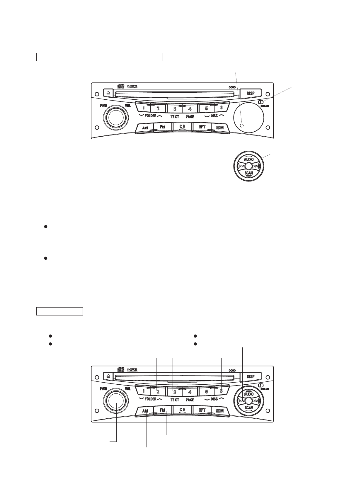
FEATURES
Audio Amp
Including high power 4CH Amp.
Adjustment of BASS,TREBLE, FADER and BALANCE by the
audio adjustment button.
Sound preset function. (Sound adjustment state can preset
the 6 sorts.)
Auto loudness function varies a frequency characteristic by
volume.
The function that controls the amount of change in the low /
high frequency tone (BASS / TREBLE) adjustment with the
maximum volume.
ATC (Auto Tone Control) function that controls the low / high
frequency tone (BASS / TREBLE) by radio-field strength at
the receipt of AM.
Radio
FM and AM can preset the 6 stations.
Improvement in the tuning operationality by the Auto store
function.
TUNE button is a double function button operating of auto-
matic tuning and manual tuning.
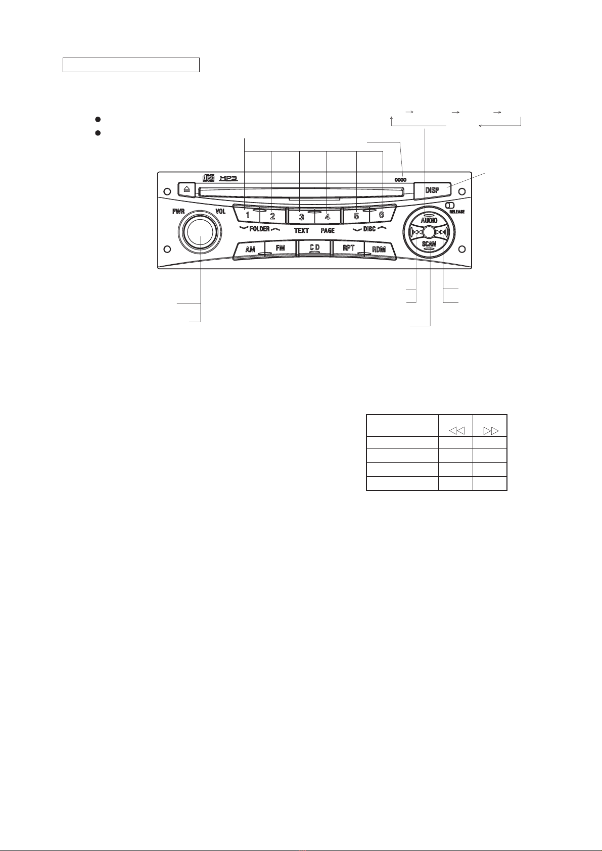
CD Player
Power Loading / Power Eject function.
Skip recovered function.
(Recovered the condition before skip.)
Protected function of laser pick-up stopping at high tempera-
ture.
Quick track selection function.
Fast-forward / fast-rewind replay function.
Repeat function. (One tune)
Scan function : 10 sec
Available for loading both 8cm and 12cm disc.
Random play function.
Any time Eject function. (Eject at the all mode included ACC
OFF.)
CD-MP3 reproduction function.
(CD-DA/MP3 coexistence disc, TITLE/ID3tag display, MPEG-
1 AUDIO Layer3, MPEG-2 AUDIO Layer3)
Others
CD auto changer / in-dash CD changer operating function.
M-BUS is used the method of communication with CD auto
changer, in dash CD changer, MD player and LCD monitor.
The connection of speaker wiring can check by test mode of
the beep in the vehicle's assembly line.
Each mode is display on the connected LCD monitor (audio
display).
Control of panel buttons illumination and the connected
LCD illumination brightness by rheostat.
Telephone mute function.
Telephone voice interrupt function.
Stereo AUX input terminal equipnment.
Even during BATT OFF, the channel preset memory is re-
tained (usage of EEPROM).
The beep sounds, to check an operation, by using a button
with hold-pushing operation function (using the buzzer on the
vehicle side).
Theft prevention security function by PANEL OUT. (Blink
alarm-flash LED at ACC OFF.)
Put out lights of the lamp by PANEL OUT at ILL ON.
SPECIFICATIONS
FM Radio
Frequency Range : 87.5 ~ 108.0MHz
(SEEK:50kHz / STEP:25kHz)
Intermediate Frequency : 10.7MHz
Sensitivity (-3dB Limiting) : Less than 14dB(µV)
AM Radio
Frequency Range : 531 ~ 1629kHz
(SEEK:9kHz,1kHz / STEP:1kHz)
Intermediate Frequency : 450kHz
Sensitivity (20dB S/N) : Less than 32dB(µV)
CD Player
Laser : Semiconductor Laser
DA Convertor : 16bit
Dynamic Range : More than 65dB
Signal/Noise Ratio : More than 65dB
Channel Separation : More than 40dB
Others
Power Supply : DC 12V (11~16V)
Test Voltage 13.2V
Negative ground
Battery Back Up Current : Less than1.0mA
Current Consumption : ACC 2.4A ± 20%
(Output 1W)
: ACC 10A ± 20%
(MAX.Output)
Maximum Power Output : 25W x 4
Output Impedance : 4
Dimensions : 178(W) x 169(D) x 50(H)mm
Weight : 1.3kg

3
Detachable Key Board (DKB)
To effectively prevent theft of the car stereo, the Control Key
Board can be removed rendering the set absolute use-
less.
How to remove the Key Board:
Slide the RELEASE switch rightward, and take the Key
Board out of panel when it comes lose. (When the Key
Board is removed, the power is turned off.)
How to reinstall the Key Board:
Side it in its original position and push it in slightly until it is
locked. (At that time, the power is automatically switched
on.)
Always keep the surface of electric contacts of the Key
Board clean to prevent malfunctions due to the dust or rust.
Alarmed Flash
When switching off the ignition key, the set flashes the red
ALARMED light to indicate the set under armed condition
against the theft.
OPERATION
DETACHABLE KEY BOARD (DKB) PART
RELEASE Switch
ALARM FLASH
PARTIAL PANEL OUT
RADIO PART
RADIO ON Button (AM)
Memory and Preset Channel Button
Memory : Push the button 1.5 seconds or more.
Preset : Push the button less than 1.5 seconds.
Tuning Up/Down Button
Step : Push the button less than 0.5 seconds.
Seek : Push the button 0.5 seconds or more.
Power ON/OFF (Push)
Volume Control(Endless) RADIO ON Button (FM) SCANButton
Automatic tuning in improvement button.
(Reception for the 10 seconds)

4
CD Mode Button
CD CD-X CD Changer
CD Changer Disc Selection Down Button
CD, CD CHANGER PART
CD Scan Button
Track Selection Up Button
(Push the button less than 0.5 seconds)
Fast-forward Button
(Push the button 0.5 seconds or more)
Track(File) Selection Up Button (MP3)
(Push the button 0.5 seconds or more)
CD Changer Disc Selection Up Button
EJECT Button CD SLOT
Repeat Play Button Track Selection Down Button
(Push the button less than 0.5 seconds)
Fast-rewind Button
(Push the button 0.5 seconds or more)
Track(File) Selection Down Button(MP3)
(Push the button less than 0.5 seconds)
<Coexistence Disc Operation Transition>
(Push the button less than 1.5 seconds,
and the operation sound is generated.)
CD-DA MP3 AUX
FOLDER Selection Up Button(MP3)
FOLDER Selection Down Button(MP3) PAGE Sender Button(MP3)
Random Play Button
TEXT Selection Button(MP3)
<For CD-TEXT>
Display usually(Track and elapsed time) Disc Name Track Name
<For MP3>
[Title display usually]
Display usually(FOLDER, Track and elapsed time) FOLDER Name File Name
[ID3-TAG Title display]
Display usually(FOLDER, Track and elapsed time) Album(assistance display) (in
two seconds)Album Title Track(assistance display) (in two seconds)FileName-
Folder Name Artist(assistance display) (in two seconds)Artist
The display mode is changed by the pushing the botton long press.
[Title display usually] [ID3-TAG Title display]

5
AUDIO & OTHERS PART
1)Level Control BASS/TREBLE/FADER/BALANCE
Push the AUDIO Button to select function among BASS/
TREBLE/FADER/BALANCE.
At the each AUDIO mode, push AUDIO Control Up/Down
Button to change its level according to the indication as the
right or below display.
After 7 seconds, the previous screen will be automatically
resumed.
AUDIO Control
BASS _+
TREBLE _+
FADER R F
BALANCE L R
Button
Up
Down
Power ON/OFF (Push)
Volume Control (Endless)
AUDIO Control Up Button
AUDIO Control Down Button
DISPLAY Button
SCANButton
When the scan operation reaches the first track of
which first 10 seconds was played, it is automati-
cally and normal playback starts.
AUDIO Control
Mode Selection Button
BASS TREBLE FADER BALANCE
Cancel
ID code
Function Setting OFF Button Function Setting ON Button
AUDIO Control Memory and Preset Channel Button
Memory : Push the button 1.5 seconds or more.
Preset : Push the button less than 1.5 seconds.

6
REAR VIEW and CONNECTORS
1: M-BUSY
2: M-DATA
3: REMO SIG 1
4: _
5: TEL MUTE 1
6: TEL SIG 1
7: TEL GND 1
8: M-SCK
9: Shield Earth
10: REMO SIG 2
11: _
12: Aux L
13: Aux R
14: Aux GND
14P CONNECTOR (J802)
1: Signal GND
2: BUS L
3: _
4: BUS R
5: _
6: _
7: Accessory ( + )
DIN 13P CD Changer CONNECTOR (J801)
1: Speaker FR ( + )
2: Speaker FL ( + )
3: Illumination ( + )
4: Antenna +B
5: Speaker RL ( + )
6: Speaker RR ( + )
7: Speaker FR ( _)
8: Speaker FL ( _)
9: Illumination ( _)
10: Battery ( + )
11: Accessory ( + )
12: _
13: Speaker RL ( _)
14: Speaker RR ( _)
14P CONNECTOR (P901)
12345
6
7
14 13 12 11 10 9 8
43 21
87 6 5
12 11 10 9
13
H
14P CONNECTOR (J802) DIN 13P CD Changer
CONNECTOR (J801)
TERMINAL EARTH
ANTENNA SOCKET
1234567
891011121314
14P CONNECTOR (P901)
8: _
9: Battery ( + )
10: Illumination ( + )
11: M-BUSY
12: M-SCK
13: M-DATA
H: Shield Earth

7
SYSTEM CONFIGURATION
Shield Earth
M-SCLK
M-BUSY
M-DATA
Battery
Shield Earth
Accessory
Illumination(+)
Illumination(_)
RV Meter
(DU-467-1)
Audio
DY-2X64WT-2-TH
CD Changer
(CD-5000C)

8
BLOCK DIAGRAM
EEPROM
BR93LC56FV
MAIN µ-COM
µPD780076GK-699-9ET
Panel Key
PLL-IC
LC72151VS
RDS Decoder
BU1924F
ELE-VOL
LC75411UES
PCB-PANEL
PCB-MAIN
M-Bus
CCB-Bus
TUNER
184E-3AF
(F.E.+FM-IF)
Connector
P901
Connector
J801
M-Bus
Buffer
8V Power
Supply Circuit
Power-IC
LA4742
Low-Boost
Circuit
CD-7
Mecha
5V Power
Supply Circuit
Output
9V Power
Supply Circuit
Connector
P801
12V
Connector
J802
RV meter
PST-3464
RESET
XTAL
8MHz
ANALOG SW
CD4066BPWR
BUFFER
NJM4565V
3.3V Power
Supply circuit
S-818A33AUC-BGN
FE1 IC201 IC802
X201
XTAL
4.332MHz
IC101
XTAL
10.35MHz
X101
IC305
X801
IC301
IC3A1
IC302
IC803
IC981
LEVEL SHIFTER
IC804 IC805
BUFFER AMP
NJM4565V
IC303
IC304
BUFFER AMP
NJM4565V
Antenna
SN74AHC2G34HDCTR
LEVEL SHIFTER
SN74AHCT244
IC801

9
DISASSEMBLING PROCEDURES
2. Removal of CD7 (See Fig.2)
1) Unscrew the four screws ( ).
2) Remove the FLAT-CABLE 18P.
3) Remove the CD7.
1
2
3
1
2
4 (M)
COVER
PLATE-SPR
PLATE-SPR
(J)
1
(J)
(Fig.1)
3
4 (L)
CD7
FLAT-CABLE 18P
(Fig.2)
1. Removal of PLATE-SPR and COVER (See Fig.1)
1) Unscrew the two screws ( ).
2) Remove the two PLATE-SPR.
3) Unscrew the four screws ( ).
4) Remove the COVER.

10
3. Removal of HEAT-SINK and BRACKET-DECK (See Fig.3)
1) Unscrew the two screws ( ) and the two screws ( ).
2) Remove the HEAT-SINK.
3) Remove the two screws ( ).
4) Remove the BRACKET-DECK.
4. Removal of ASSY-PNL and CHASSIS-F (See Fig.4)
1) Remove the ASSY-PNL and SHEET-CD.
2) Remove the two screws ( ).
3) Remove the CHASSIS-F.
4
5
6
7
5
62 (M)
42 (P)
HEAT-SINK
BRACKET-DECK
(M)
5(M)
(Fig.3)
7
2 (M)
ASSY-PNL
SHEET-CD
CHASSIS-F
(Fig.4)

11
5. Removal of PCB-MAIN (See Fig.5)
1) Unscrew the two screws ( ).
2) Unscrew the one screw ( ).
3) Unscrew the two screws ( ) and the three screws ( ).
4) Unlatch the five hooks ( a ).
5) Remove the PCB-MAIN.
6. Removal of PCB-PANEL (See Fig.6)
1) Remove the KNOB-VOL.
2) Remove the seven screws ( ).
3) Remove the PCB-PANEL.
8
9
10
11
12
10
(a)
PCB-MAIN
(N)
11
(M)
9
(N)
8
2 (M)
10
(N)
11
(M)
11
(M)
(Fig.5)
12
7 (K)
PCB-PANEL
KNOB-VOL
(Fig.6)

12
EXPLODED VIEW and PARTS LIST
M002 246L48229 FLAT-CABLE 18P B-2
M003 560J26213 CHASSIS-B C-3
M004 560J28711 CHASSIS-F A-3
M005 *570L46110 SPRING-REL B-2
M006 *570L46010 SPRING-REL B-2
M007 591K53610 COVER A-1
M008 591K40711 BRACKET-DECK C-1
M009 *591K47311 PLATE-E B-2
M010 592L763O1 PLATE-SPR B-2,C-3
M011 635J07410 HEAT-SINK C-1
M012 641J031O5 CLAMP B-2
M013 641J031O6 CLAMP B-2
M014 645L02210 BUSH-DIN C-1
M015 643L06710 CUSHION A-3,B-3
M016 643L30310 SHEET-CD A-2
M017 *643L44810 SHEET B-2
M018 *643L44811 SHEET A-2
M019 *643L44812 SHEET B-1
M020 *702J67513 PANEL-2E54 A-2
M021 *704K83513 BUTTON-CH1 B-2
M022 *704K83613 BUTTON-CH2 B-2
M023 *704K83713 BUTTON-DISP B-2
M024 *704K83813 BUTTON-EJECT A-2
M025 *704K84015 BUTTON-RELEASE B-2
M026 734L468O6 KNOB-VOL A-2
M027 *761J15711 PRISM-MAIN B-1
M028 *761K34111 PRISM-CD A-2
M031 *892L38019 ASSY-PNL A-2
M032 *892L38113 ASSY-SUB A-2
M033 *942K46011 CD7WMA(955211) B-3
M034 593L29210 HOLDER-TR C-2
M035 943M208O6 NAME-CARD A-1
J 653P02046 SCREW-MC-FLAT M3X6 -
K 653P33014 SCREW-P-BIND 2X6 -
L 653P13028 SCREW-S-BIND 2.6X6S -
M 653P11046 SCREW-S-PAN 3X6 -
N 653P11048 SCREW-S-PAN 3X10 -
P 653P11052 SCREW-S-PAN 3X16 -
Q 669L057O1 SCREW-TAP 3X6 -
R 669L057O2 SCREW-TAP 2.6X6 -
S 653P03085 SCREW-MC-BIND M5X16 -
Ref. No. Part No. Description Index
* : Marked parts are unregistered.
ABC
1
2
3
M002
M003
M004
M005
M006
M007
M008
M009
M010
M010
M011
M012
7
K
M013
M014
M015
M015
M016
M017
M018
M019
M020
M021
M022
M023
M024
M026
M027
M028
M035
M031
M032
M033
4
L
2
M
2
M
4
M
M
M
M
M
M
M
M
N
N
S
2
R
2
Q
2
P
M025
J
J
N
1
1
M034

13
IC EXPLANATION
IC802 BR93LC56FV
IC3A1 LA4742
Instruction decode
Control
Clock generation
4
3
1
2
DO
DI
SK
CS
Instruction
register
Dummy bit
Address
buffer
Data
register
Address
decoder
R/W
amp.
Writing
prohibition
High voltage
generator
Voltage power supply
detection
2,048 bit
EEPROM array
7 bit 7 bit
16 bit 16 bit
Muting &
ON Time Control
Circuit
Ripple
Filter
Protective
circuit
Protective
circuit
Mute
circuit
Aux
circuit
Stand by
Switch
Clip
Detect
Circuit
16 14 1 15 10 4 12 25 11
9
6
20
7853222171918212324
13
ON TIME
PWR GND4
PWR GND3
PWR GND2
PWR GND1
OUT4
OUT4+
OUT3
OUT3+
OUT2
OUT2+
OUT1
OUT1+
MUTE
IN 4
PRE GND
AUX IN
IN 3
R.F
ST BY
IN 2
CLIPDET
IN 1
Vcc1/2
Vcc3/4
1
Vref
2
4
VDD
VSS
VOUT
IC803 PST-3436

14
IC305 CD4066BPWR IC302~304 NJM4565V-TE1
LVref
LVref
LVref
RVref
RVref
RVref
LVref
RVref
VDD
Multiplexer
CONTROL
CIRCUIT
Multiplexer ZERO CROSSDET
ZERO CROSSDET
LOGIC CIRCUIT
CCB
INTERFACE
NO SIGNAL
TIMMER
36
L3
35
L4
37
L2
38
L1
40
Vref
41
R1
42
R2
43
R3
44
R4
34
LSELO
33
LVRIN
32
LCT
31
LCOM
30
LVROUT
29
LTIN
28
LF1C1
27
LF1C2
26
LF1C3
25
LF3C1
24
LTOUT
1
RSELO
2
RVRIN
3
RCT
4
RCOM
5
RVROUT
6
RTIN
7
RF1C1
8
RF1C2
9
RF1C3
10
RF3C1
11
RTOUT
23 LFIN
22 LFOUT
21 LROUT
19 CL
18 DI
17 CE
15 TIM
14 RROUT
13 RFOUT
12 RFIN
39
VDD
16 TEST
20 VSS
IC301 LC75411UES
SW
A
IN/OUT SIG A VDD
CONT A
CONT D
IN/OUT SIG D
IN/OUT
OUT/IN
OUT/IN SIG C
IN/OUT
CONT B
CONT C
Vss
OUT/IN SIG B
OUT/IN
SW
D
SW
B
SW
C
14
13
12
11
10
9
8
1
2
3
4
5
6
7
1
2
3
4
8
7
6
5
OUT A
IN A
+IN A
V
+V
OUT B
IN B
+IN
AB

15
Reference
Voltage
5 1
2
VIN
VSS
VOUT
ON/OFF
CIRCUIT
4
ON/OFF
Parasitic DIODE
IC981 S-818A33AUC-BGN-T2G
IC805 SN74AHCT244PWR
IC980 LF33AB-DT-TR
1
2
3
4
8
7
6
5
1A
GND
3Y
2A
VCC
1Y
3A
2Y
IC804 SN74AHC2G34HDCTR
16
14
18
12
1Y1
1Y2
1Y3
1Y4
9
3
7
2Y3
2Y2
2Y1
2Y4
5
8
13
2
4
1
6
19
1OE
1A1
1A2
1A3
2A1
2OE
1A4
2A2
11
15
2A4
2A3
17
1
INHIBIT
CONTROL
V
IN
3V
OUT
2
GND
REFERENCE
VOLTAGE
TERM.
PROTECTION
DRIVER
CURRENT
LIMIT
DUMP
PROTECTION
START
INHIBIT ERROR
AMPLIFIER

16
IC101 LC72151VS-TRM
REFERENCE
DIVIDER
PHASE DETECTOR
CHARGE PUMP
UNLOCK
DETECTOR
PDS
CHARGE PUMP
for FAST LOCK
FAST LOCK UP
CONTROL
POWER
ON
RESET
CCB
I/F
SWALLOW COUNTER
1/16,1/17 4bits
12bits PROGRAMMABLE
DIVIDER
UNIVERSAL
COUNTER
DATA SHIFT REGISTER
LATCH
21
23
20
18
17
16
22
24
25
13
19
12
14
15
4
30
1
8
9
10
11
6
7
29 28 27 26 2 3 5
XBUF
XIN
XOUT
FMIN
AMIN
HCTR/I-3
LCTR/I-4
VDD
VSS
CE DI CL DO I/O-1 I/O-2 O-3
PDM1
PDM2
TGI1
PDF
AOUT2
AIN1
PDS
TGI2
TGO
AIN2
AVDD
AREF
AVSS
AOUT1

17
R1A,18,etc. 103L299O9 R-CHIP 0
R343A,443A 103L290O1 R-CHIP 10
R731~733A 103L190O2 R-CHIP 12
R731B~733B 103L190O3 R-CHIP 15
R912,913 103L290O5 R-CHIP 22
R4,11,etc. 103L291O3 R-CHIP 100
R122 103L291O7 R-CHIP 220
R931 103L241O9 R-CHIP 330
R852B,933,973 103L291O9 R-CHIP 330
R971 103L292O1 R-CHIP 470
R780,790 103L292O2 R-CHIP 560
R701,712,etc. 103L292O4 R-CHIP 820
R784,794,etc. 103L292O5 R-CHIP 1k
R702,703,etc. 103L292O6 R-CHIP 1.2k
R704,715 103L292O7 R-CHIP 1.5k
R705,716 103L292O8 R-CHIP 1.8k
R327 103P502O8 R-CHIP 1.8k
R116,340,etc. 103L292O9 R-CHIP 2.2k
R343,443 103P502O9 R-CHIP 2.2k
R707,783,793 103L293O0 R-CHIP 2.7k
R11B,124B,etc. 103L293O1 R-CHIP 3.3k
R898B,898C,898D
103L193O2 R-CHIP 3.9k
R903,904 103L243O2 R-CHIP 3.9k
R124A,350,etc. 103L293O2 R-CHIP 3.9k
R123,849 103L293O3 R-CHIP 4.7k
R710,771,835A 103L293O4 R-CHIP 5.6k
R711,773 103L293O5 R-CHIP 6.8k
R121 103L293O6 R-CHIP 8.2k
R10B,11A,etc. 103L293O7 R-CHIP 10k
R934 103L293O8 R-CHIP 12k
R12,13,etc. 103L293O9 R-CHIP 15k
R329,344,etc. 103P503O9 R-CHIP 15k
R911 103L294O0 R-CHIP 18k
R330,345,445 103P504O0 R-CHIP 18k
R112B,923,932 103L294O1 R-CHIP 22k
R10A,353,453 103L294O3 R-CHIP 33k
R12A,13A,etc. 103L294O5 R-CHIP 47k
R16A 103L294O6 R-CHIP 56k
R835B,863B,etc. 103L294O9 R-CHIP 100k
R3A1,3A2,etc. 103P504O9 R-CHIP 100k
C3A3,4A3,7A3 141L180O6 C-CERAMIC-CHIP 5pF
C1 141L181O5 C-CERAMIC-CHIP 15pF
C130 141L181O7 C-CERAMIC-CHIP 18pF
C101,108,etc. 141L182O5 C-CERAMIC-CHIP 39pF
C4,12A,etc. 141L160O9 C-CERAMIC-CHIP 1000pF
C902F 141L162O3 C-CERAMIC-CHIP 0.015µF
C901F 141L065O5 C-CERAMIC-CHIP 0.022µF
C12,13,etc. 141L163O3 C-CERAMIC-CHIP 0.022µF
C117 141L164O3 C-CERAMIC-CHIP 0.033µF
C124,350A,etc. 141L164O5 C-CERAMIC-CHIP 0.068µF
C124A,430A,835B
141L162O1 C-CERAMIC-CHIP 0.01µF
C390,391,etc. 141L164O6 C-CERAMIC-CHIP 0.1µF
C11,12B,etc. 141L164O8 C-CERAMIC-CHIP 0.22µF
C116 141L169O1 C-CERAMIC-CHIP 0.68µF
C106A,810A 141L069O5 C-CERAMIC-CHIP 1µF
C824A 141L069O1 C-CERAMIC-CHIP 2.2µF
R12B,13B,976 103L295O1 R-CHIP 150k
R859B,977 103L295O3 R-CHIP 220k
R3N2,3N3 109P01226 R-NETWORK-CHIP 2.2
R3N1,8N1,8N2 109P01218 R-NETWORK-CHIP 1k
Part No. L
141L06xOx 2.0mm
141L16xOx 1.6mm
141L18xOx 1.6mm
Part No. L
103L19xOx 2.0mm
103L24xOx 3.2mm
103L29xOx 1.6mm
103P50xOx 1.6mm
ELECTRICAL PARTS LIST
< CHIP PARTS (RESISTORS & CAPACITORS) >
SOLDERING PART
L
CHIP PARTS (RESISTORS)
Ref. No. Part No. Description Ref. No. Part No. Description
CHIP PARTS (CAPACITORS)
TRANSISTORS
Q911 260L021O3 TR 2SD1858Q
Q901,930,etc. 260P68210 TR 2SD2375OP
Q11,782,etc. 260M061O6 TR-CHIP 2SA1037R
Q911A,972 260M061O3 TR-CHIP 2SC2412R
Q12,13,etc. 260M061O5 TR-CHIP 2SC2412S
Q770,780,790 260L010O1 TR-CHIP 2SD601A
Q772 260L042O4 TR-CHIP DTA114T
Q981 260M061O1 TR-CHIP DTA124E
Q923,931 260L030O5 TR-CHIP DTA143E
Q835,960 260L042O2 TR-CHIP DTA144T
Q998 260L057O1 TR-CHIP DTB123Y
Q859 260L014O7 TR-CHIP DTC115E
Q16,811,etc. 260M061O2 TR-CHIP DTC124E
Q921 260L042O1 TR-CHIP DTC124T
Q982 260M061O8 TR-CHIP DTC144E
Q12A,13A,etc. 260L033O1 TR-CHIP DTC323T
DIODES
D900 264P437O2 DIODE ERA83-004-PN-R-B
D831,861,etc. 264L060O1 DIODE-CHIP 1SS355

18
S801 452P151O4 CONNECTOR 12P
P801 452P153O4 CONNECTOR 12P
P901 452L34211 CONNECTOR 14P
J802 452P23214 CONNECTOR 14P
J803 452P177O8 CONNECTOR 18P
ANT1 449L076O2 SOCKET-ANT
J801 449L098O3 SOCKET-DIN 13P
L1,910 351L171O3 COIL-CHOKE
L901 351P11510 COIL-CHOKE
L106,113 351P082O4 COIL-CHOKE-CHIP
D901 264L076O3 DIODE-CHIP AA1101W-740-TR
D829 264L037O1 DIODE-CHIP DCC010
D852 264P617O1 DIODE-CHIP MC2836T
D904 264P516O1 DIODE-CHIP S3D6600
D911 264P583O9 DIODE-Z MA8062H
D931 264L067O3 DIODE-Z-CHIP MA8051M
D980 264P583O8 DIODE-Z-CHIP MA8062M
D859 264P584O1 DIODE-Z-CHIP MA8068M
D921 264P584O7 DIODE-Z-CHIP MA8082M
D902 264P585O0 DIODE-Z-CHIP MA8091M
D971 264P585O3 DIODE-Z-CHIP MA8100M
D311,411,etc. 264P588O6 DIODE-Z-CHIP MA8270M
IC802 263P973O1 IC BR93LC56FV
IC305 263P02711 IC CD4066BPWR
IC3A1 266P524O1 IC LA4742
IC101 263P04310 IC LC72151VS-TRM
IC301 263P160O3 IC LC75411UES
IC980 266P59010 IC LF33AB-DT-TR
IC302~304 266L065O9 IC NJM4565V-TE1
IC803 263P05236 IC PST-3436
IC981 262P09733 IC S-818A33AUC-BGN-T2G
IC804 263L061O2 IC SN74AHC2G34HDCTR
IC805 263L060O9 IC SN74AHCT244PWR
IC801 262P53120 IC µPD780076GK-665-9ET
Ref. No. Part No. Description
RF941 103L390O1 R-FUSE
RF900 103L390O2 R-FUSE
IC
COILS
CONNECTORS
OTHERS
PL901~906 253L47610 LAMP-CHIP
X101 285L012O6 CRYSTAL
FE1 295P21524 TUNER-AMFM
X801 299L030O2 RESONATOR-CHIP
Z1 299P136O2 PROTECTOR-CHIP
VOL721 430L026O1 SW-ROTARY
SW901 432L115O2 SW-PUSH
SW701~717 432P02010 SW-PUSH 2P
H-IC1 593L69911 HOLDER-IC
H-TR1,2 593L70010 HOLDER-TR
PLATE1,2 593L70110 PLATE-G
RESISTORS

19
PCB-MAIN
TO PCB-PANEL
(S801)
PARTS LAYOUT ON PRINTED CIRCUIT BOARD
MODEL : DY-2X64WT-2-TH (PARTS SIDE)

20
PCB-MAINPCB-MAIN
TO CD-CHANGER
TO CENTER DISPLAY
TO CD7
PARTS LAYOUT ON PRINTED CIRCUIT BOARD
MODEL : DY-2X64WT-2-TH (PATTERN SIDE)
Table of contents
Other Mitsubishi Car Receiver manuals

Mitsubishi
Mitsubishi DY-1MU3E21-T User manual

Mitsubishi
Mitsubishi DY-1MU3R45-T User manual

Mitsubishi
Mitsubishi MZ360119EX(DPXMP2090SM4) User manual

Mitsubishi
Mitsubishi CQ-JB3160AA User manual

Mitsubishi
Mitsubishi MZ360236EX(KDC336AXAM4) User manual

Mitsubishi
Mitsubishi CQ-EB6260L User manual

Mitsubishi
Mitsubishi DY-5MU4R69-T-3 User manual

Mitsubishi
Mitsubishi MMES User manual

Mitsubishi
Mitsubishi DY-6MW7U53-2 User manual

Mitsubishi
Mitsubishi MZ360216EX User manual