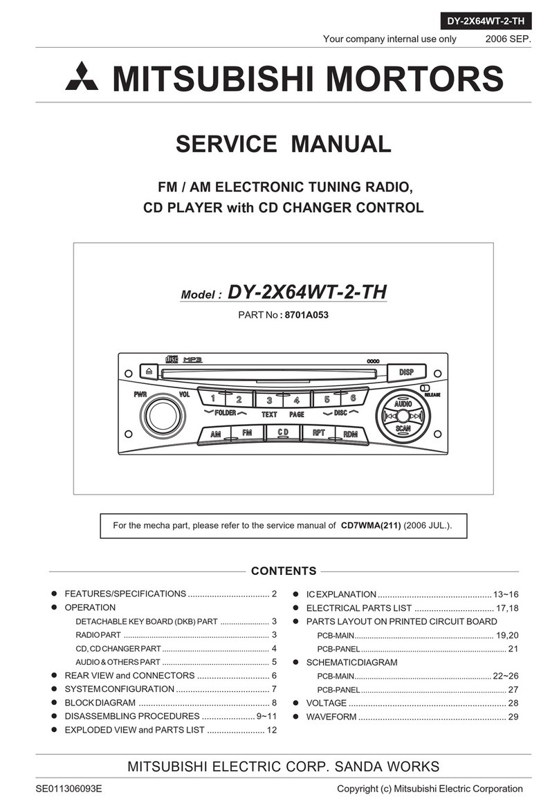
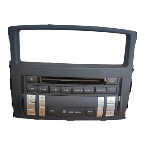
Mitsubishi DY-5MU4R69-T-3 User manual

SERVICE MANUAL
MITSUBISHI ELECTRIC CORP. SANDA WORKS
Your company internal use only.
DY-5MU4R69-T-3,4
Copyright (C) Mitsubishi Electric Corporation.
SE060914083E Ver.pptx14E
MITSUBISHI MOTORS 2014 Oct.
AM / FM-ST ELECTRONIC TUNING RADIO,
CD PLAYER
CONTENTS
Model : DY-5MU4R69-T-3 (For MMC)
DY-5MU4R69-T-4 (For MMNA)
● DISASSEMBLING PROCEDURES ............................. 2~18
● PARTS LIST.................................................................19,20
● ELECTRICAL PARTS LIST........................................ 21~36
MELCO Code : 34U587, 34W936
PART No. : 8701A587, 8701A587
* Refer to the Service Manual for DY-5MU4R69-T,-2
(34U277, 34W894) unless otherwise stated in this.

2Your company internal use only.Copyright (C) Mitsubishi Electric Corporation.
DY-5MU4R69-T-3,4
DISASSEMBLING PROCEDURES
M020(1) : NAME-CARD(DY-5MU4R69-T-3)
M031(2) : NAME-CARD(DY-5MU4R69-T-4)
*It is assembling procedure. Disassembling procedure is in reverse.
M019(1)/M030(2) : LABEL
(1) DY-5MU4R69-T-3
(2) DY-5MU4R69-T-4
Mode l

3Your company internal use only.Copyright (C) Mitsubishi Electric Corporation.
DY-5MU4R69-T-3,4
DISASSEMBLING PROCEDURES
M025 : ASSY-KNOB
S2-CHASSIS
●Disassembling procedures
In reverse of assembling procedures.
●Assembling procedures
1. Attach M025 to S2-CHASSIS.

4Your company internal use only.Copyright (C) Mitsubishi Electric Corporation.
DY-5MU4R69-T-3,4
DISASSEMBLING PROCEDURES
Ⓔx 3
●Disassembling procedures
In reverse of assembling procedures.
●Assembling procedures
1. Fit tab C of M012 on tab C of S2-CHASSIS (2 places) to direction arrow.
And fit tab D of M012. (4 places)
2. Screw S2-CHASSIS and M012 with Ⓔ. (3 places)
S2-CHASSIS
S2-CHASSIS
No. Screw Tighten torque(N・m)
Ⓔ2.6X6 0.5 +0.2/-0.1
M012 : COVER

5Your company internal use only.Copyright (C) Mitsubishi Electric Corporation.
DY-5MU4R69-T-3,4
DISASSEMBLING PROCEDURES
Ⓔx 4
●Disassembling procedures
In reverse of assembling procedures.
●Assembling procedures
1. Insert M003 to S2-DECK and PCB-MEDIA.
*Lock connector after inserting M003.
2. Positioning S2-DECK to S2-CHASSIS and fit S2-DECK to S2-CHASSIS.
*Handling range of S2-DECK is follow the indicates in view on left.
*Rearranging method is follow the indicates in view on right.
3. Screw S2-CHASSIS and S2-DECK with Ⓔ. (4 places)
No. Screw Tighten torque(N・m)
Ⓔ2.6X6 0.5 +0.2/-0.1
S2-DECK
S2-CHASSIS
S2-CHASSIS
M003 : FLAT-CABLE 18P
S2-DECK
S2-DECK
M003 S2-DECK
M003
S2-DECK
M003

6Your company internal use only.Copyright (C) Mitsubishi Electric Corporation.
DY-5MU4R69-T-3,4
DISASSEMBLING PROCEDURES
S2-CHASSIS
Ⓐx 2
No. Screw Tighten torque(N・m)
Ⓐ2.6X6 0.5 +0.2/-0.1
Ⓐx 2
●Disassembling procedures
In reverse of assembling procedures.
●Assembling procedures
1. Insert M002 to the connector of S2-PANEL. (Connector D)
*Lock connector after inserting M002.
2. Fit tab E of S2-CHASSIS on square hole E of S2-PANEL (7 places),
Screw S2-CHASSIS and S2-PANEL with Ⓐ. (4 places)
3. Insert M002 to the connector of S2-CHASSIS. (Connector E)
*Lock connector after inserting M002.
S2-PANEL
M002 : FLAT-CABLE 30P

7Your company internal use only.Copyright (C) Mitsubishi Electric Corporation.
DY-5MU4R69-T-3,4
DISASSEMBLING PROCEDURES
M004 : FLAT-CABLE 60P
●Disassembling procedures
In reverse of assembling procedures.
●Assembling procedures
1. Insert M004 to the connector A and B.
*Lock connector after inserting M004.
S2-CHASSIS S2-CHASSIS

8Your company internal use only.Copyright (C) Mitsubishi Electric Corporation.
DY-5MU4R69-T-3,4
DISASSEMBLING PROCEDURES
●Disassembling procedures
In reverse of assembling procedures.
●Assembling procedures
1. After put M005 to M014, tab A and B of M014 fit on tab A and B of M009 and screw with Ⓔ. (2 places)
2. Insert lead to connector A.
3. Fitting tab D after inserting the convex position of S3-CHASSIS
into the locating hole of M009.
4. Screw M009 and S3-CHASSIS with Ⓔ. (9 places)
Ⓔx 11
No. Screw Tighten torque(N・m)
Ⓔ2.6X6 0.5 +0.2/-0.1
M014,M005
M009 M005 : MOTOR-FAN
M014 : HOLDER-FAN
M009 : CHASSIS-REAR
S3-CHASSIS

9Your company internal use only.Copyright (C) Mitsubishi Electric Corporation.
DY-5MU4R69-T-3,4
DISASSEMBLING PROCEDURES
S3-CHASSIS
●Disassembling procedures
In reverse of assembling procedures.
●Assembling procedures
1. After inserting the convex position of S3-CHASSIS into the locating hole of M008,
screw M008 and S3-CHASSIS with Ⓔ. (4 places)
Ⓔx 4
No. Screw Tighten torque(N・m)
Ⓔ2.6X6 0.5 +0.2/-0.1
M008 : CHASSIS-F

10 Your company internal use only.Copyright (C) Mitsubishi Electric Corporation.
DY-5MU4R69-T-3,4
DISASSEMBLING PROCEDURES
●Disassembling procedures
In reverse of assembling procedures.
●Assembling procedures
1. Insert the locating convex of S4-CHASSIS into the locating groove of CHASSIS-M. (2 places)
2. Screw CHASSIS-M and S4-CHASSIS with Ⓔ. (3 places)
3. Screw M016 and S4-CHASSIS with Ⓔ(3 places) and Ⓕ. (2 places)
4. Screw S4-CHASSIS and CHASSIS-M with Ⓕ. (1 place)
CHASSIS-M
S4-CHASSIS
Ⓔx 4
ⒻⒻ
Ⓔx 2
M016 : HEAT-SINK
No. Screw Tighten torque(N・m)
Ⓔ2.6X6 0.5 +0.2/-0.1
Ⓕ2.6X12 0.5 +0.2/-0.1
Ⓕ

11 Your company internal use only.Copyright (C) Mitsubishi Electric Corporation.
DY-5MU4R69-T-3,4
DISASSEMBLING PROCEDURES
Ⓔx 7
M007 : CHASSIS-M
M027 : ASSY-PCB-MEDIA-T
No. Screw Tighten torque(N・m)
Ⓔ2.6X6 0.5 +0.2/-0.1
●Disassembling procedures
In reverse of assembling procedures.
●Assembling procedures
1. Insert the locating convex of M007 into the locating hole of M027. (2 places)
And fit M027 to M007.
2. Screw M027 with Ⓔ. (7 places)

12 Your company internal use only.Copyright (C) Mitsubishi Electric Corporation.
DY-5MU4R69-T-3,4
DISASSEMBLING PROCEDURES
Ⓔx 4
No. Screw Tighten torque(N・m)
Ⓔ2.6X6 0.4 ±0.1
●Disassembling procedures
In reverse of assembling procedures.
●Assembling procedures
1. Insert 4 tabs of M021 to 4 holes of M029, and twist 4 tabs.
2. After inserting locating hole on M021 into locating convex on M006,
screw with Ⓔ. (4 places)
M021 : S5-PCB-MAIN-T
M006 : CHASSIS-B
M029 : ASSY-PCB-DCDC-T
M029

13 Your company internal use only.Copyright (C) Mitsubishi Electric Corporation.
DY-5MU4R69-T-3,4
DISASSEMBLING PROCEDURES
●Disassembling procedures
In reverse of assembling procedures.
●Assembling procedures
1. After inserting the locating convex of M013 into the locating hole of M026,
screw M026 and M013 with Ⓓ. (2 places)
2. Note that M026 handling prohibited area.
No. Screw Tighten torque(N・m)
Ⓓ3X6 0.8 +0.2/-0.1
Ⓓx 2
M026
M013 : HOLDER-CD8
M026 : CD8-MECHA-T(955832)

14 Your company internal use only.Copyright (C) Mitsubishi Electric Corporation.
DY-5MU4R69-T-3,4
DISASSEMBLING PROCEDURES
M022
Rearranging point of M022
Ⓒx 2
No. Screw Tighten torque(N・m)
Ⓒ2.6X6 0.4 ±0.1
Ⓒx 2
M001 : FLAT-CABLE 10P
S3-LCD
S3-LCD
M022.
ASSY-PANEL
M022 : ASSY-PANE
●Disassembling procedures
In reverse of assembling procedures.
●Assembling procedures
1. Insert M022 between locating rib on ASSY-PANEL. *Refer to the Fig.A.
2. After inserting locating hole B on S3-LCD into locating pin B on ASSY-PANEL and snap on.
3. After inserting locating hole A on S3-LCD into locating pin A on ASSY-PANEL and screw with Ⓒ. (4 places)
*Be careful not to roll up the FPC of M022 then.
4. Certainly fasten FPC on M022, after insert FPC on M022 into connector on S3-LCD.
*Refer to the Fig.B.
5. Certainly fasten M001, after insert M001 into connector on ASSY-PANEL and S3-LCD.
Detail of M022 assembly work
M022.
*FPC at the position same as a detailed drawing.
(The right side of the bottom center.)

15 Your company internal use only.Copyright (C) Mitsubishi Electric Corporation.
DY-5MU4R69-T-3,4
DISASSEMBLING PROCEDURES
No. Screw Tighten torque(N・m)
Ⓑ2X6 0.2 +0.15/-0.04
Ⓑx 4
●Disassembling procedures
In reverse of assembling procedures.
●Assembling procedures
1. After inserting locating hole on PCB-SW-R into locating pin on M024, and screw with Ⓑ. (4 places)
2. After inserting locating hole on PCB-SW-L into locating pin on M024, and screw with Ⓑ. (3 places)
Ⓑx 3
M024 : ASSY-PANEL
PCB-SW-L
PCB-SW-R

16 Your company internal use only.Copyright (C) Mitsubishi Electric Corporation.
DY-5MU4R69-T-3,4
DISASSEMBLING PROCEDURES
●Disassembling procedures
In reverse of assembling procedures.
●Assembling procedures
1. Bend FPC-1 of HOLDER-LCD-RE. *Refer to lower figure.
2. After inserting locating hole on M028 into locating pin on HOLDER-LCD-RE (2 places) and screw with Ⓔ. (6 places)
3. Insert FPC-1 into connector on M028 and certainly fasten connector of M028.
4. Insert FPC-2 into connector on M028 and certainly fasten connector of M028.
Ⓔx 6
No. Screw Tighten torque(N・m)
Ⓔ2.6X6 0.5 +0.2/-0.1
HOLDER-LCD-RE
M028 : ASSY-PCB-MONI-T

17 Your company internal use only.Copyright (C) Mitsubishi Electric Corporation.
DY-5MU4R69-T-3,4
DISASSEMBLING PROCEDURES
Ⓖx 2
●Disassembling procedures
In reverse of assembling procedures.
●Assembling procedures
1. Insert locating pin-A of M015 to the locating hole-A of M010 then screw with Ⓖ. (2 places)
2. Pass FPC-1 of ASSY-LCD through the hole (A) of M010, and snap on catch hooks-A of M015
into part-B of ASSY-LCD. (Refer to the Fig.E. 3 places)
3. Pass FPC-2 of ASSY-LCD through the hole (B) of M011, and snap on catch hooks-C of M011
into part-D of ASSY-LCD. (Refer to the Fig.F. 3 places)
4. Insert locating pin-B of M011 to the locating hole-B of M010. then screw with Ⓖ. (2 places)
Ⓖx 2
ASSY-LCD
M011 : HOLDER-LCD-L
M015 : HOLDER-LCD-R
M010 : HOLDER-LCD-RE
ASSY-LCD
M010
M010
M011
ASSY-LCD
M010
ASSY-LCD
M015
No. Screw Tighten torque(N・m)
ⒼM2X2 0.2 +0.15/-0.04

18 Your company internal use only.Copyright (C) Mitsubishi Electric Corporation.
DY-5MU4R69-T-3,4
DISASSEMBLING PROCEDURES
●Disassembling procedures
In reverse of assembling procedures.
●Assembling procedures
1. Bending the FPC of M023. (Reference to the Fig.J.)
2. Stick TAPE-POLYESTER to M023. (Reference to the Fig.H and Fig.K.)
3. Stick M017 (2 places) and M018 (2 places) to M023, after remove the protection sheet of M023.
When attach M017 and M018, carry the ends of release paper of M017 and M018.
Refer to the figure on the right and below.
*Stick M017 and M018 so as not cover glass of M023 and not stick form of M023.
4. After attach, remove the release paper of M017 and M018. M023 : ASSY-LCD
M023 :
ASSY-LCD
M017 : SHEET-TP
M017 : SHEET-TP
M018 : SHEET-TP FPC
M023
M023
M023
M023
Bending point of the FPC.
TAPE-POLYESTER
TAPE-
POLYESTER

19 Your company internal use only.Copyright (C) Mitsubishi Electric Corporation.
DY-5MU4R69-T-3,4
PARTS LIST
< DY-5MU4R69-T-3 >
Ref. No. Parts No. Parts Name Page Ref. No. Parts No. Parts Name Page
M001 246L52068 FLAT-CABLE 10P P.14 M019 851L76236 LABEL P.2
M002 246L52069 FLAT-CABLE 30P P.6 M020 959M030O7 NAME-CARD(DY-5MU4R69-T-3) P.2
M003 246L52115 FLAT-CABLE 18P P.5 M021 931L65419 S5-PCB-MAIN-T P.12
M004 246L58910 FLAT-CABLE 60P P.7 M022 890P17910 ASSY-PANE P.14
M005 288P10215 MOTOR-FAN P.8 M023 890P18012 ASSY-LCD P.18
M006 590J55010 CHASSIS-B P.12 M024 892K54715 ASSY-PANEL P.15
M007 590J55112 CHASSIS-M P.11 M025 892K54811 ASSY-KNOB P.3
M008 590J55210 CHASSIS-F P.9 *M026 940L24423 CD8-MECHA-T(955832) P.13
M009 590J55310 CHASSIS-REAR P.8 M027 943M443O9 ASSY-PCB-MEDIA-T P.11
M010 590J55410 HOLDER-LCD-RE P.17 M028 943M444O1 ASSY-PCB-MONI-T P.16
M011 591K84510 HOLDER-LCD-L P.17 M029 943M444O2 ASSY-PCB-DCDC-T P.12
M012 591K84610 COVER P.4 A 653P13428 SCREW-S-BIND 2.6X6 -
M013 591K84710 HOLDER-CD8 P.13 B 653P33014 SCREW-P-BIND 2X6 -
M014 594L10110 HOLDER-FAN P.8 C 653P33028 SCREW-P-BIND 2.6X6 -
M015 594L51610 HOLDER-LCD-R P.17 D 655P01046 SCREW-D-PAN 3X6 -
M016 635L09111 HEAT-SINK P.10 E 655P03028 SCREW-D-BIND 2.6X6 -
M017 644L19010 SHEET-TP P.18 F 655P03033 SCREW-D-BIND 2.6X12 -
M018 644L19011 SHEET-TP P.18 G 653P01556 SCREW-MC-PAN-PR1B M2X2 -
* Marked part is the ASSY replacement.

20 Your company internal use only.Copyright (C) Mitsubishi Electric Corporation.
DY-5MU4R69-T-3,4
PARTS LIST
< DY-5MU4R69-T-4 >
Ref. No. Parts No. Parts Name Page Ref. No. Parts No. Parts Name Page
M001 246L52068 FLAT-CABLE 10P P.14 M021 931L65419 S5-PCB-MAIN-T P.12
M002 246L52069 FLAT-CABLE 30P P.6 M022 890P17910 ASSY-PANE P.14
M003 246L52115 FLAT-CABLE 18P P.5 M023 890P18012 ASSY-LCD P.18
M004 246L58910 FLAT-CABLE 60P P.7 M024 892K54715 ASSY-PANEL P.15
M005 288P10215 MOTOR-FAN P.8 M025 892K54811 ASSY-KNOB P.3
M006 590J55010 CHASSIS-B P.12 *M026 940L24423 CD8-MECHA-T(955832) P.13
M007 590J55112 CHASSIS-M P.11 M027 943M443O9 ASSY-PCB-MEDIA-T P.11
M008 590J55210 CHASSIS-F P.9 M028 943M444O1 ASSY-PCB-MONI-T P.16
M009 590J55310 CHASSIS-REAR P.8 M029 943M444O2 ASSY-PCB-DCDC-T P.12
M010 590J55410 HOLDER-LCD-RE P.17 M030 851L76237 LABEL P.2
M011 591K84510 HOLDER-LCD-L P.17 M031 959M030O8 NAME-CARD(DY-5MU4R69-T-4) P.2
M012 591K84610 COVER P.4 A 653P13428 SCREW-S-BIND 2.6X6 -
M013 591K84710 HOLDER-CD8 P.13 B 653P33014 SCREW-P-BIND 2X6 -
M014 594L10110 HOLDER-FAN P.8 C 653P33028 SCREW-P-BIND 2.6X6 -
M015 594L51610 HOLDER-LCD-R P.17 D 655P01046 SCREW-D-PAN 3X6 -
M016 635L09111 HEAT-SINK P.10 E 655P03028 SCREW-D-BIND 2.6X6 -
M017 644L19010 SHEET-TP P.18 F 655P03033 SCREW-D-BIND 2.6X12 -
M018 644L19011 SHEET-TP P.18 G 653P01556 SCREW-MC-PAN-PR1B M2X2 -
* Marked part is the ASSY replacement.
This manual suits for next models
1
Table of contents
Other Mitsubishi Car Receiver manuals

Mitsubishi
Mitsubishi NR-261UM-07LAN5 User manual

Mitsubishi
Mitsubishi CQ-JB3160AA User manual

Mitsubishi
Mitsubishi CQ-EB6260L User manual

Mitsubishi
Mitsubishi DY-6MW7U53-2 User manual

Mitsubishi
Mitsubishi MZ360119EX(DPXMP2090SM4) User manual

Mitsubishi
Mitsubishi DY-2X64WT-2-TH User manual

Mitsubishi
Mitsubishi DY-1MU3R45-T User manual

Mitsubishi
Mitsubishi MMES User manual
Mitsubishi
Mitsubishi MZ360216EX User manual

Mitsubishi
Mitsubishi MZ360236EX(KDC336AXAM4) User manual