2
FEATURES and SPECIFICATIONS
SPECIFICATIONS
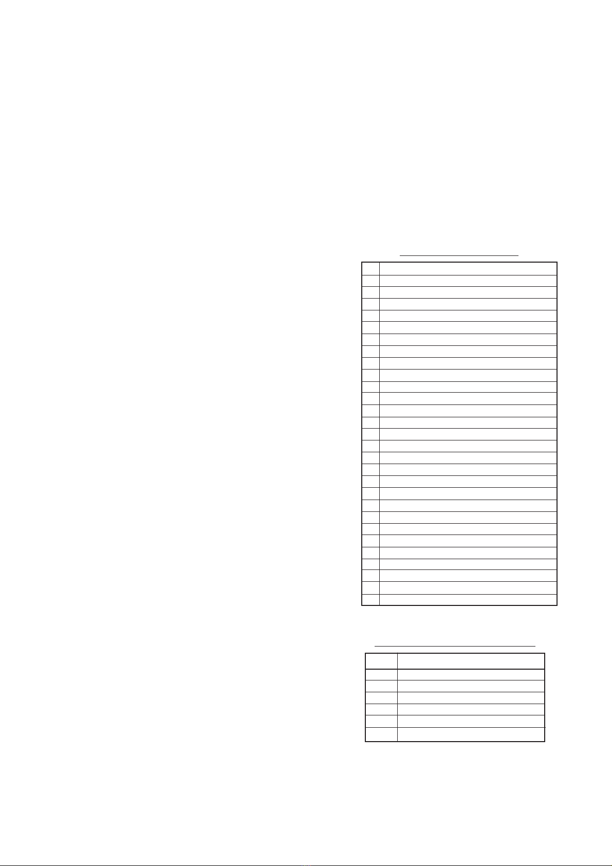
AM (MW) Radio
Frequency Range
EU : 522 ~ 1611kHz (9kHz step)
AUS
: 531 ~ 1710kHz (9kHz step)
CHI
NA : 531 ~ 1620kHz (9kHz step)
GCC : 531 ~ 1602kHz (1kHz step)
ROW : 531 ~ 1710kHz (1kHz step)
Sensitivity : Less than 32dB
Signal/Noise Ratio : More than 6dB
(15dBµV)
FM Stereo Radio
Frequency Range
EU / AUS / CHI
NA : 87.5 ~ 108.0MHz (0.1MHz step)
GCC / ROW : 87.5 ~ 108.0MHz (0.025MHz step)
Separation Characteristic : More than 14dB (43dBµV)
Signal/Noise Ratio : More than 17dB
LW Stereo Radio (EU only)
Frequency Range : 153 ~ 279kHz (1kHz step)
Sensitivity : Less than 32dB
Signal/Noise Ratio : More than 6dB
(15dBµV)
CD Changer
Dynamic Range : More than 65dB
Signal/Noise Ratio : More than 65dB
Channel Separation : More than 55dB (1kHz)
Others
Power Supply : DC 13.2V (10.0~16.0V)
Negative ground
Battery Back Up Current : 1mA
Current Consumption : BATT 2.4A ± 20% (Output 1W)
Maximum Power Output : 35W
x
4ch
Output Impedance : 4 (SP Output)
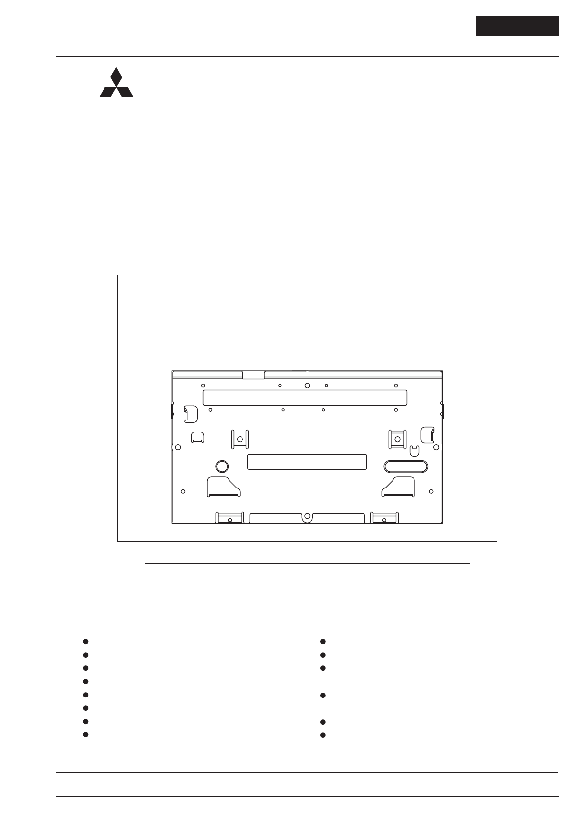
Dimensions : 178mm x 151.3mm x 100mm
( W
x
D x
H )
Weight : 2.1kg
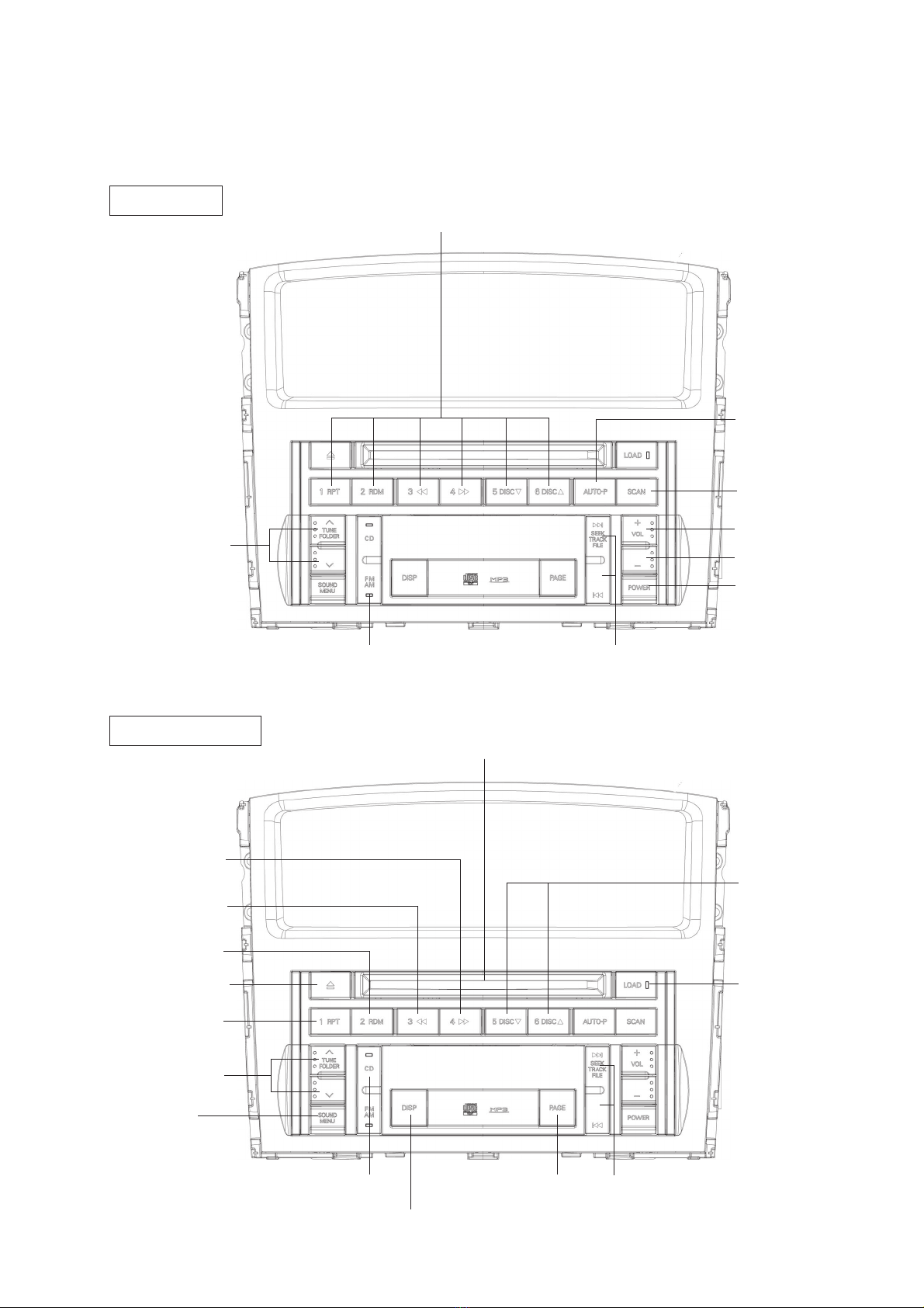
FEATURES
Radio
Manual preset function / Store 6 AM(MW) stations.
Manual preset function / Store some FM stations. (EU : 18
stations / AUS, CHINA, GCC and ROW : 6 stations)
Manual preset function / Store 6 LW stations. (EU only)
Auto Preset function / Store 6 AM stations and 6 FM sta-
tions. (AUS, CHINA, GCC and ROW only)
Auto Store function / Store 6 AM stations and 6 FM sta-
tions. (EU only)
Tune control function. (Rotary Switch)
ATC function. (Control BASS and TREBLE, Only AM
mode)
AM noise killer function. (AM-NK)
RDS function. (EU only)
CD Changer
Built-in CD auto changer. (6 disc)
Power load / Power eject function.
Protecting laser pickup. (As high temperature)
Fast track up and Fast track down function.
Any Time Load function. (All mode and ACC OFF)
Any Time Eject function. (All mode and ACC OFF)
Reload function.
Supporting only 12cm disc. (Not supporting 8cm disc)
MP3 play function.
(MPEG1 AUDIO LAYER3, MPEG2 AUDIO LAYER3)
Shock proof memory.
Continuous loading the disc. (Long pushing LOAD button)
Continuous ejecting the disc. (Long pushing EJECT button)
Title display function.
Fast-forwarding and fast-reversing function.
[CD-DA]
Repeat function. (1 track / 1 disc)
Random function. (1 disc / All disc)
[MP3]
Folder Up / Down function. (TUNE knob)
Repeat function. (1 file / 1 folder)
Random function. (1 folder / All folder)
Audio Part
High power, 4 ch output. (4 load)
Adjustment of BASS, MID, TREBLE (± 6 step) and BAL-
ANCE, FADER (± 11 step). (TUNE knob)
Fixed-EQ (6 band x 4 ch) / Adjusting the sound filed char-
acteristic.
Auto loudness function / Changing the frequency charac-
teristic.
Limiting the value (BASS, TREBLE) as volume MAX.
Connecting the AMP and the RSES.
Customizing sound characteristic / Music type, Sound
Field, BASS, MID, TREBLE, FADER, BALANCE.
Others
Sounding the beep as the long pushing button.
Interrupting the telephone voice.
Checking the speaker connection.
Operated the steering remote control.
Telephone mute function.
Changes from DY-6MW7U53
PTY is supporting Italian.


 User manual")
 User manual")