1. Application
The guided type fall arrester including a flexible anchor line is a part of the personal protective
equipment against falls from a height and should be the user’s personal property. When using long
safety ropes there is the danger of falling from a great height. With the guided type fall arrester, the
shortest connection to the full body harness of the user from the anchor point via the safety rope is
made. The guided type fall arrester clamps firmly on to vertical safety ropes. The guided type fall
arrester may only be used, according to its marking, with the designated Mittelmann sheathed core
rope 12KM. The guided type fall arrester KB1-12KM including the flexible anchor line 12KM have
also been tested for horizontal use. Here please follow the special instructions on horizontal use.
2. Use
afely secure the sheathed core rope (hereafter called simply the safety rope) with the karabiner
hook found at the upper end to an anchor point. The anchor point must guarantee a minimum load
bearing capacity of 10kN in accordance with EN 795 and must be located above the user. For safety
it is essential to choose the anchor device or the anchor point and the manner of workmanship so
that the free fall and the fall height are reduced to a minimum. In places where there is a risk of
falling, the user has to make sure that the slack rope formation is minimized. For safety, it is
essential that fall arrest systems ensure the required clearance below the user before each use, so
that in the event of a fall, no impact on the ground or any other obstacle is possible. To avoid
collisions with objects or the ground in the event of a fall, the lowest necessary height under the feet
of the user must be at least 4,0m. When using the KB1-12KM horizontally (falling over an edge) at
least 5.0 m is required.
The rope-end of the safety rope must be secured (for example, via an end splice or end knots).
Attention: Combining different components of PPE may not spoil the function of each single
component. In order to attach the guided type fall arrester to, or detach it from, the safety rope it
must be opened. For this, the procedure is as follows:
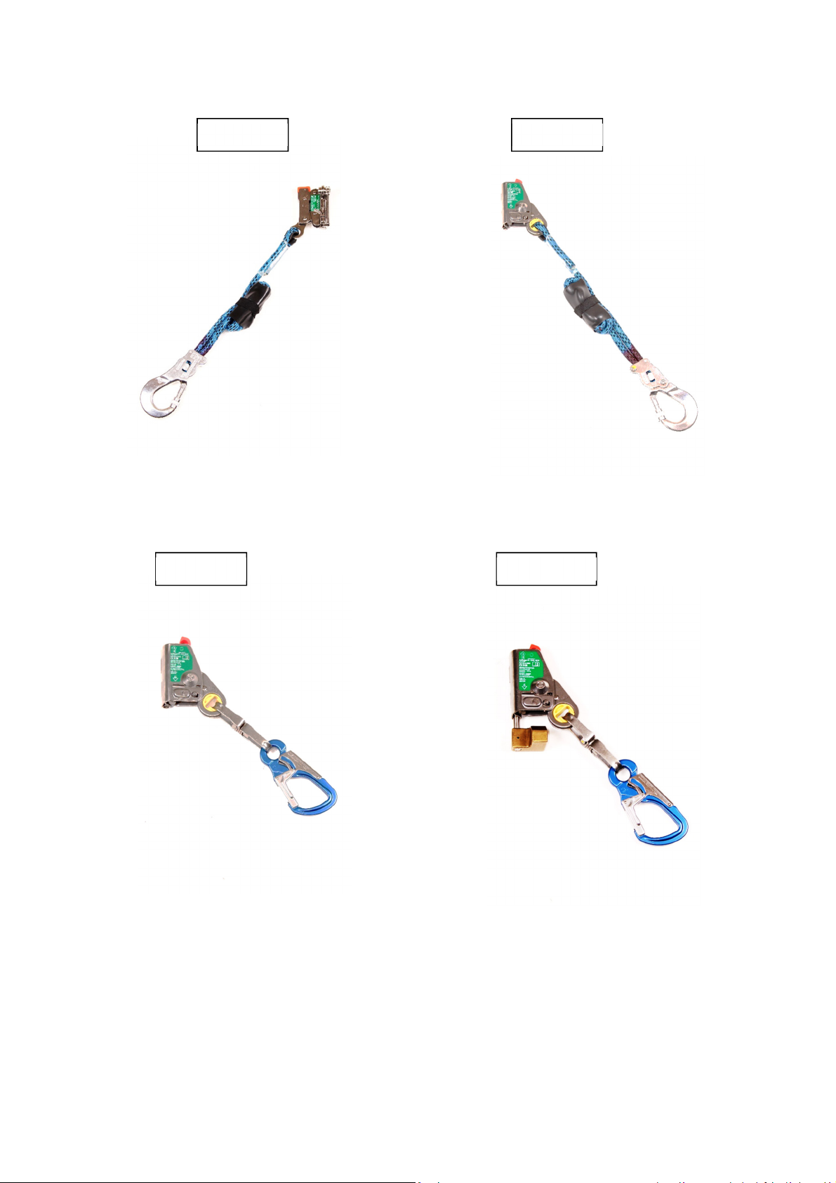
AH3-12KM / AH4-12KM / AH4F-12KM
Turn the knurled-head bolt to the left, Press down the locking lever to and while keeping it pressed
down open the device. In order to attach the device the red slider, the arrow and the sun must point
upwards. Press up the lever with the yellow lug and place the device in this position around the
safety rope and press shut. When the locking lever is locked in place, screw down the knurled-head
bolt by turning it to the right.
Function Test: Pull the device down quickly by the karabiner hook. In doing so, the device must not
slip downwards on the rope. Pull the device up by the karabiner hook. In doing so the device must
slide up the rope and, on slow slackening, also slide downwards.
KB1-12KM
For arresting devices of the type KB1 turn the swivel lever upwards and to the right. The lever stays
in this position by itself. Now release the knurled head bolt by turning it to the left. The guided type
fall arrester can now be opened by folding back. In order to attach, the red cap, the arrow and the
sun must point upwards. Place the device in this position around the safety rope and lightly press
together. Tighten the knurled-head bolt by turning it to the right and turn the swivel lever to the left. In
doing so the swivel lever springs back down to its home position in the closed condition.
Function Test: Pull the device down quickly by the karabiner hook. In doing so, the device must not
slip downwards on the rope. By operating the handle, the clamping jaws release themselves from the
rope and the device can be pushed up and down on the rope.
Now hook on and secure the karabiner hook of the guided type fall arrester in the fall arrest element
of the full body harness. Only one full body harness may be used in accordance with EN 361. The
fall arrest element should be located in a suitable position relative to the fall arrester. Preferably, a
front fall arrest element should be used. It is preferable to use a front fall arrest element at chest
height of the user.
Attention: Protect the safety rope an lanyar s against sharp-e ge objects, wel ing
sparks, chemicals an other estructive or amaging hazar s.
Before the first use, familiarize yourself with the function. Before and during use, it should be
considered how any potentially necessary rescue measures can be safely, quickly and effectively
carried out. The guided type fall arrester including a flexible anchor line should only be used by fully
trained and/or otherwise competent personnel, or the user should be under the direct supervision of
such a person. The guided type fall arrester including a flexible anchor line may only be used within