Foreword
This instrument is a Linear Gage with an ABS origin point function. To obtain the highest performance and
the longest service life from your Linear Gage, carefully read this manual thoroughly prior to setup and
operation. After reading this manual keep it near the Linear Gage for quick reference. The specifications of
this gage and the description in this manual are subject to change without prior notification.
Safety Precautions
To ensure operator safety, use the instrument in conformance with the directions and specifications given in
this User’s Manual.
zIf a contact point with a sharp tip is used, exercise sufficient care in handling during
replacement or use of it so as not to get hurt.
zIf a contact point is released freely after it has been pressed in, the contact point may burst
forth at a very high speed depending on the amount of spindle travel. Sufficiently exercise
care so that your fingers or hand may not be pinched.
Precautions for Use
Carefully avoid the following attempts and conditions to protect the instrument from failure and malfunction.
IMPORTANT
zDo not apply sudden shocks including a drop or excessive force to the linear gage.
zDo not disassemble or modify the gage.
z
Do not use and store the gage at sites where it is exposed to direct sunlight or at extremely hot or cold sites.
zTo use the gage highly accurately, avoid sites where the temperature will change abruptly.
zAbsolutely do not apply an electric engraver to the gage. The high voltage may damage electronic parts.
Also, do not use the gage at sites where it is subject to large electric noises.
zDo not exert load on the spindle in the perpendicular direction and do not twist the spindle.
zDo not clamp the stem too tightly, since the spindle will not move smoothly.
zDo not apply excessive tension to the cable or do not bend it forcibly.
zTo perform stable measurement, allow at least 10 minutes after turning on the power.
zDo not set up the origin point at either end of the stroke.
z
If the gage is used in combination with other instruments, the maximum performance could not be obtained
depending on environmental and operating conditions. Take those conditions into consideration prior to use.
z
The functions and performance will not be guaranteed, if the gage is used in other conditions than those specified.
zTale sufficient damage-preventive processing (safety measures), should this gage have been at fault.
zA contact point could hurt a workpiece depending on the workpiece material, measuring force, impact
when the contact point comes in contact with the workpiece, etc. Check that there is no problem of hurts
on a workpiece during measurement or accuracy variation depending on the measuring force, etc., in
advance of use.
Disposal of Old Electrical & Electronic Equipment (Applicable in the European
Union and other European countries with separate collection systems)
This symbol on the product or on its packaging indicates that this product shall not be treated
as household waste. To reduce the environmental impact of WEEE (Waste Electrical and
Electronic Equipment) and minimize the volume of WEEE entering landfills, please reuse
and recycle.
For further information, please contact your local dealer or distributors.
Export Control Compliance
The goods, technologies or software described herein may be subject to National or International, or
Japanese Export Controls. To export directly or indirectly such matter without due approval from the
appropriate authorities may therefore be a breach of export control regulations and the law.
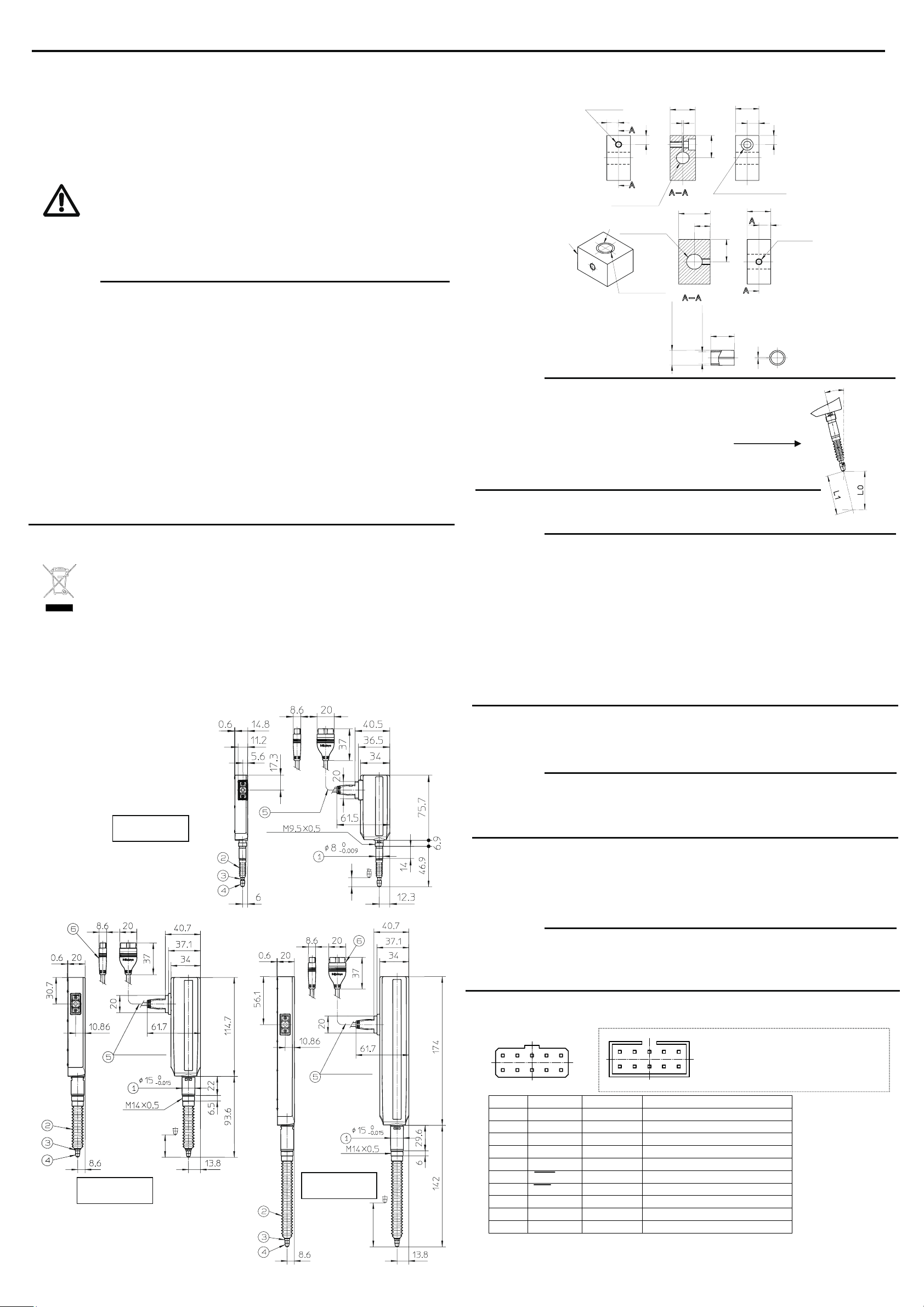
1. Name and Dimension of Each Part
(1)Stem
(2)Rubber boot
(3)Spindle
(4)Contact point
(5)Output cable
(6)Output connector
2. Mounting the Gage
To mount the gage on another instrument or a fixture, clamp the 8 stem or 15 stem.
It is recommended to use a slotted holder or a split bushing for the mount structure.
IMPORTANT
zAbsolutely avoid pressing the stem directly with set screws.
(The built-in bearing may be damaged.)
zNotice that excessively tightening the stem can cause trouble in the spindle operation.
zNever fix a linear gage at other than the stem.
zMount the gages so that the spindle is directed perpendicular to
the measured surface. If the gage is mounted at an angle to the measured surface,
an error may be generated in measurement results.
zExercise care so as not to exert a force on the gage through the cable.
3. Precautions in Protecting the Gage from Dust and Water
IMPORTANT
zThe output connector plug and preamplifier (counter side) is not protective structured. Install the gage at a
place where it is not splashed directly with water or oil.
zIf the cable covering is broken, liquid will penetrate into the gage inside due to capillary phenomenon. This
will cause damage to the gage. Immediately repair the cable.
zBe greatly careful not to damage the rubber boot due to chips, etc. If the rubber boot is damaged,
dust-proof function will be deteriorated. Immediately replace or repair the rubber boot.
zThe materials including rubber which are used for the rubber boot and other sealing parts are not universal
against diversified coolants and chemicals. If those parts deteriorate unusually, consult the nearest
Mitutoyo Service Center.
zIf linear gages are used in adverse environments where they are subject to frequent splashes of water and
oil, it is recommended to take preventive measures such as replacing them before being damaged.
zEach part of the gage is sealed up, and therefore must not be disassembled. If any part is disassembled,
the rated performance will not be obtained. Do not absolutely disassemble the gage.
4. Connecting the Gage to a Counter
Connect the output connector of the gage to the input connector on a linear gage counter (for Digimatic
input). For detailed information, refer to the user’s manual of the linear gage counter.
IMPORTANT
zIf the gage cable is close to the power line for other instruments, the gage may malfunction. Connect the
gage cable as apart from the power line as possible.
zThe power is supplied via the output data cable. Batteries can not be used as power supply.
zWhen connecting the gage head, turn off the power to the counter.
5. ABS Origin Point
With this absolute sensor, the origin point cannot be reset even if the power is turned off. When the power is
turned on, the sensor always outputs its positional data relative to the origin point.
This capability eliminates the need for repeated zero setting with a master workpiece, and significantly
contributes to automatic measurement.
IMPORTANT
zThe ABS origin point has been set near the lowest end of the stroke before shipment.
zRewriting the ABS point is performed by operating the counter. The counter may or may not have the
rewriting function depending on the gage model. Please confirm the counter specification before
purchasing a linear gage.
6. Digimatic output specifications
1) Pin assignment and signal
Pin No. Signal Input/Output Function
1 GND - Signal GND
2 DATA Output Measurements
3 CK Output Clock for transmission
*4 N.C. - Not used
5 REQ Input Request to send input
*6 ORIG Input ABS point setup signal input
*7 N.C. - Not used
*8 N.C. - Not used
*9 +5V - Power supply (+5V±10%)*4
*10 GND(F.G.) - Frame GND
*3: Signals marked * are unique to this gage. The other signals are common to the Mitutoyo Digimatic gages
(10-pin rectangular connector).
*4: Current consumption: Idd=20mA max
Applicable receptacle of the external device
Sumitomo 3M: Vertical Mount Low Profile
Header
Model No. 7610-5002XX or equivalent
Linear Gage LGD-1010L-B/1025L-B/1050L-B/1010LE-B/1025LE-B/1050LE-B No. 99MBC105B
Series No. 575
LGD-1010L-B
LGD-1010LE-B
LGD-1025L-B
LGD-1025LE-B
19
210
91
10 2
*1:For 10mm Stroke type
*2:For 25/50mm Stroke type
Cross section
Split bushing
Cross section
*2
*1
(90°with respect to tap)
+0.020
+0.005
Unit: mm
・Example2
・Example1
1
*2
15
7.
6
1
15
7.
M4x0.7thru
4.5 drill, 7.5 countersink, 4.4dee
2
1
7.
M4x0.7thru
1
15
6
8
15
*2
*1
10
17
(1)
(1)
Notch position
(2)
(2)
1
15
8
*1
*2 17
10
*1
+0.024
+
+0.020
+0.005
+0.024
+0.006
0
-
0
-
+0.020
+
+0.024
+
NOTE
(Thread height)
Cable length = L
(Thrust stem mounting screw)
10.6 or more
(stroke)
(Thread height)
Cable length = L
Thrust stem
mounting screw
26 or more
(stroke)
(Thread height)
Cable length = L
Thrust stem
mounting screw
51.5 or more
(stroke)
LGD-1050L-B
LGD-1050LE-B
θ
Error = L0 - L1