STS LABEL APPLICATOR STS808-3 User manual
V.2.00
LABEL APPLICATOR
FOR ONE AND TWO LABELS
STS808-3
User manual
STS 808
LABEL APPLICATOR
MC
phone: (+359) 66 801 536 fax: (+359) 801 547
[email protected] www.stselectronics.eu


V.2.00
Technical data
Power supply: 220Vac, 50Hz.
Own consumption: < 100VA.
Electrical connecting: cable with plug type 'SHUKO'.
Dimensions: 365mmW, 245mmH, 330mmD.
Diameter of the container: 25 ... 160mm.
Length of the container: 80 ... 240mm.
/distance between the container guides/
Diameter of label roll: < 200mm.
Spool diameter: 50 ... 70mm.
Roll / Label Width: 25 ... 150mm.
Label length: 25 ... 500mm.*
Distance between the labels: > 2,5mm.
Pulling speed: 0,1m/s.
* the sum of the lengths of the two labels should not be greater than the circumference
of the container.
- 2 - STS808
Description
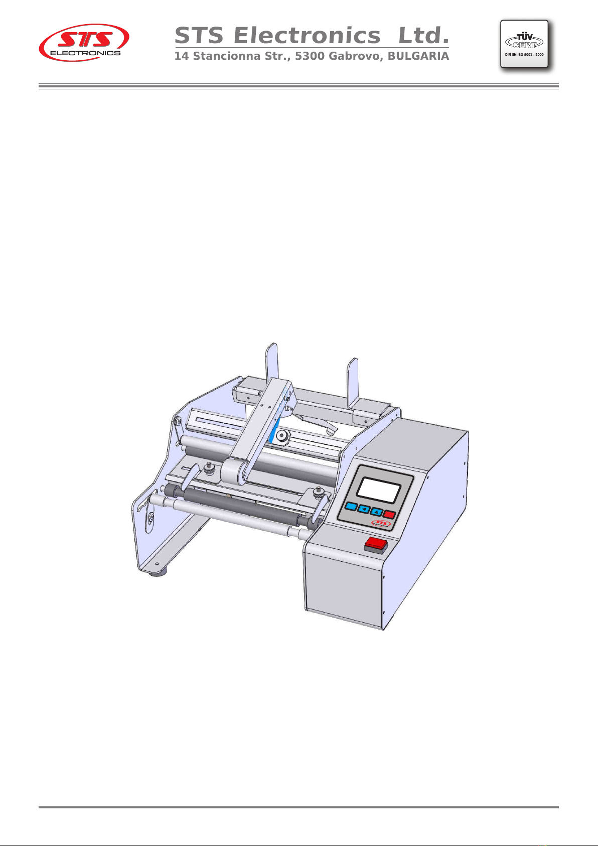
The machine is designed to place one or two self-adhesive labels (front and rear) on
cylindrical containers of different diameter and length with smooth walls. The labels must be
on one roll, (front and rear - placed consecutively) on the roll guide.
The containers need to be placed and removed manually. The beginning of the work is
performed by pressing the built-in 'Start' button or by an external start / 'Start' pedal
connected to the intended coupling /.
The control panel allows you to count the labels which has been used.
phone: (+359) 66 801 536 fax: (+359) 801 547
[email protected] www.stselectronics.eu
Preparation for work and setup.
The orientation of the container (left-right) is selected, depending on the direction of
the printed labels. Adjust the pressure arm and idler roller according to the diameter of the
container. Adjust the guides so that the container is in the middle of the working area.
The label roll is placed on the Label bar so that the labels are against the gluing area.
The position is fixed with the two magnetic roll guides. The roller drag arm is positioned in the
center of the roller.
The pressure roller is "unlocked" by moving forward. Label bar is loaded according to
the attached scheme. The sensor is positioned so that labels pass through its working area. It
is trained according to the attached manual. Next to the peel edge is positioned the beginning
of the label (front - with two labels). The pressure roller is locked. The guides of the label strip
are positioned and fixed to the edges without compressing it.
Set the required parameters in the machine menu. Start without a container for
control. The new label (front label - with two labels) must be up to the peeling edge. If
necessary, adjustments are made.
At any time, pressing the C button for more than 3 seconds causes the counter to be
reset.
The brightness and contrast of the display can be changed as desired.
- 3 -
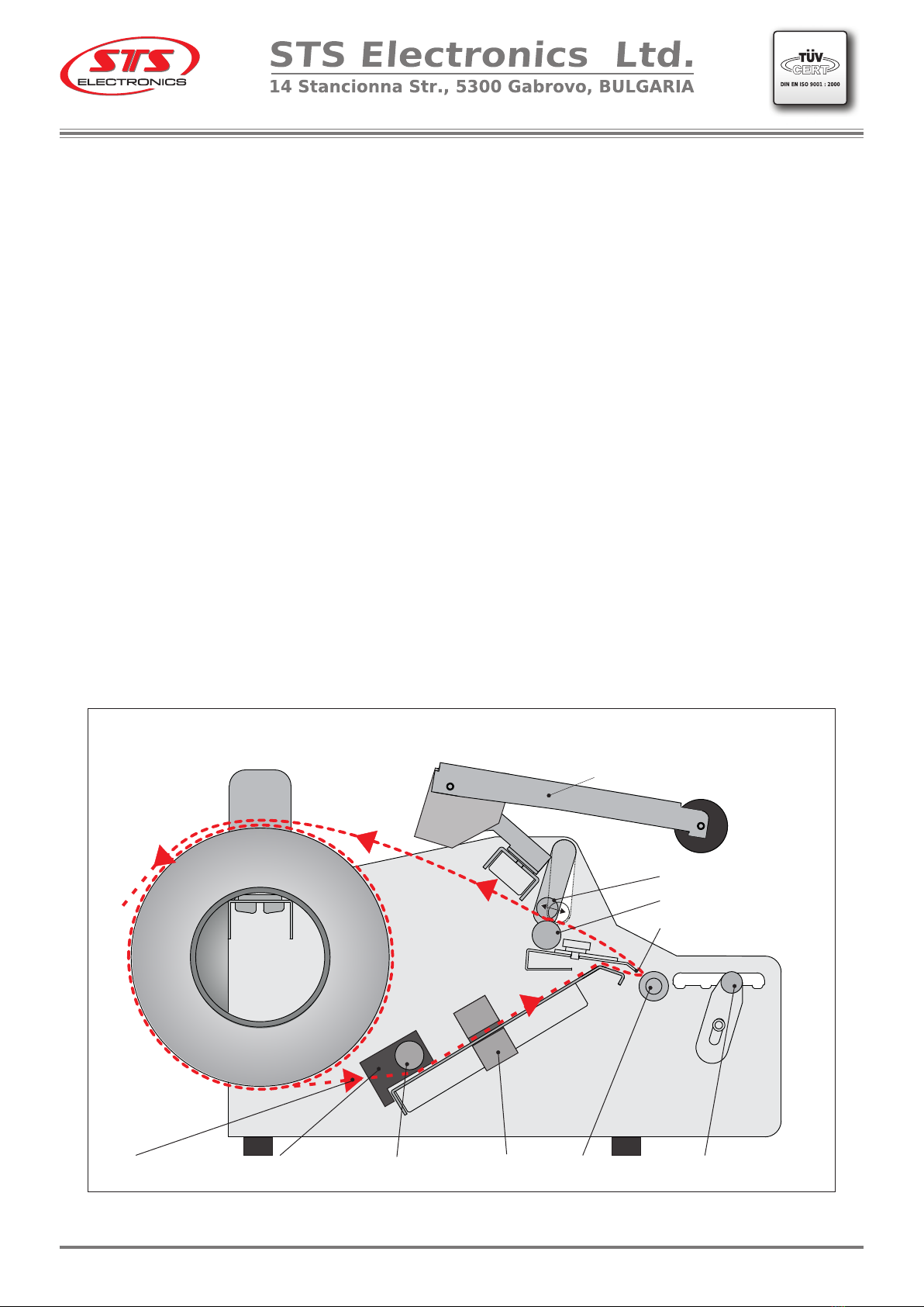
Label Path Diagram
Pulling roller
Pressure roller
Peel edge
Label Path Drive roller Container idler
roller
SensorGuiding rollerGuiders
Container pressure arm
V.2.00STS808
phone: (+359) 66 801 536 fax: (+359) 801 547
[email protected] www.stselectronics.eu

- 4 -
STS 808
LABEL APPLICATOR
MC
Control Panel
Button ‘Start’
Peel Edge
Drive Roller
Idler Roller
Pulling Roller
Pressure Roller
Magnetic Roll Guides
Label Roll Bar
Label Drag Arm
Container Guides
Container Pressure Arm
V.2.00STS808
Pressure Mechanism
Guiding Roller
Connector for external start
Power Connector
Power Switch
Magnetic Roll Guides
Label Guides
Label Drag Arm
Guides for Labels
Label Sensor
phone: (+359) 66 801 536 fax: (+359) 801 547
[email protected] www.stselectronics.eu

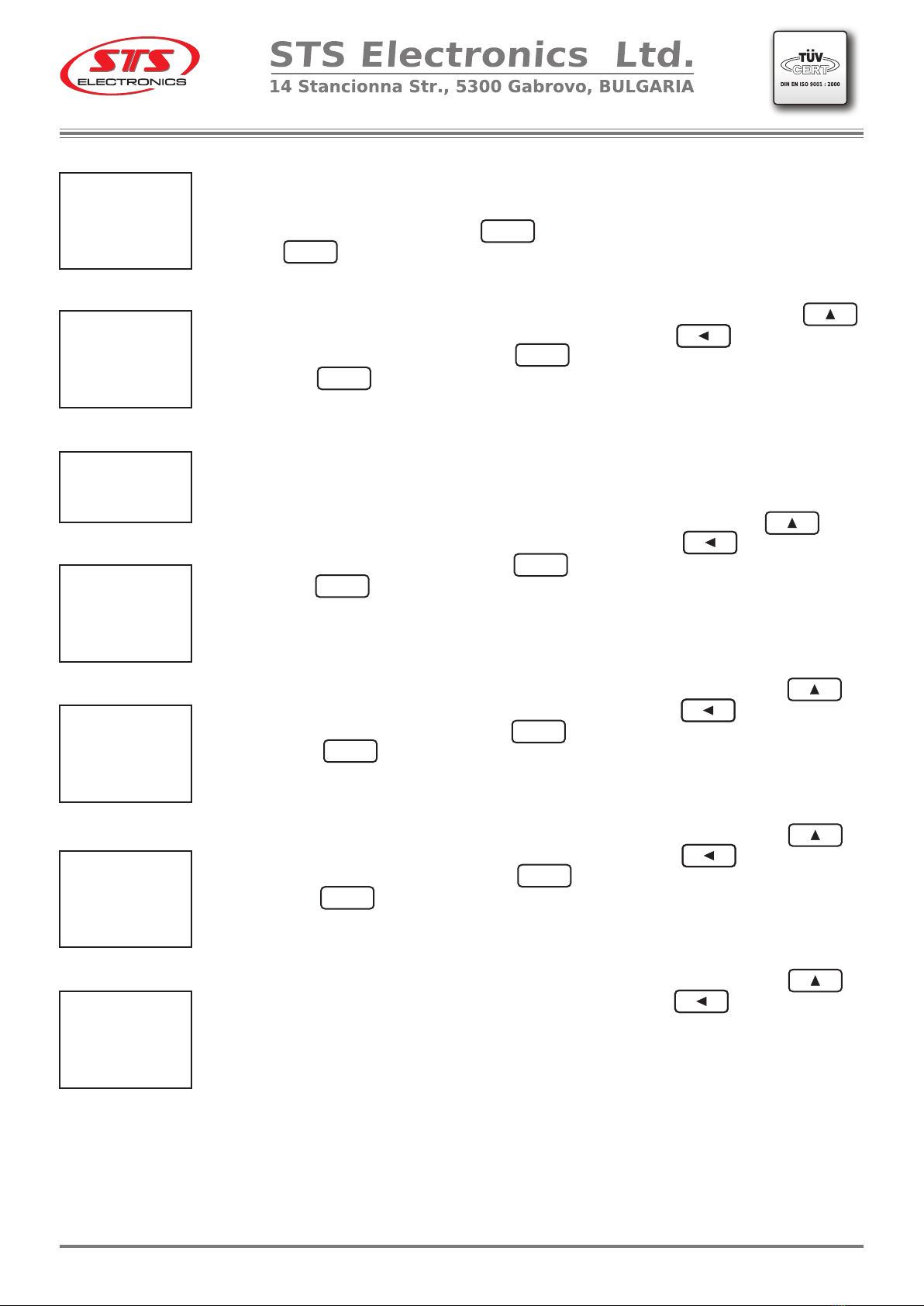
After the machine is switched on, an advertisement logo, the
machine type / one label - 1, two labels - 2 or the combined version - 3 /, the
software version will be displayed. After that will be shown the operating
mode - fig.1.
The labeling process is performed by pressing the built-in 'Start'
button or by an external start / 'Start' pedal connected to the connector /.
The display shows the execution - fig.2. Upon completion of the process,
the label counter grows. If you want to reset the counter you can just press
the button at any time more than 3 seconds.
Access to the menu is password protected. By pressing and holding
the button for more than 3 seconds, a password window is displayed
- fig.3. Cancel by pressing the button and accessing the input menu
by pressing the button - fig.4. Entering the password is done by
changing the digit by pressing the button .
Moving to the next digit is done by pressing the button By pressing
the button returns you at the beginning to enter the password.
The password for this machine is 8083 - it is static and can not be
change by the user. When the password is incorrect on the screen comes
up notice for error - fig.5. By pressing button starts from beginning to
enter the correct password fig.3. By pressing the button cancel the
password menu and the control panel is returning in operating mode - fig.1.
A correctly entered password gives access to parameter changes.
The first window to display is a language selection - fig.6. By pressing the
button language is changing cyclically - fig.7. Confirm the desired
choice by pressing The next parameter is mode selection / 1, 2
labels/ - fig.8.
By pressing the button ONE LABEL / TWO LABELS mode is
cyclically changed. Confirm the desired choice by pressing the button
Select mode ‘ONE LABEL’.
When selecting 'ONE LABEL' mode and confirming it, proceed to the
next parameter - offset stop - fig.9. Its value determines the correct
positioning of the beginning of a next label to the peeling edge. Its
determination depends on the length of the label and is given in
Application 1.
Entering is done by changing the digit by pressing the button
Moving to the next digit is done by pressing the button The process
is cyclical.
- 5 -
Control Panel and Setup
MODE 1 LABEL
------------------------------
WAIT START
000
NUMBER LABELS
fig.1
MODE 1 LABEL
------------------------------
EXECUTION
001
NUMBER LABELS
fig.2
PASSWORD
------------------------------
* * * *
PASSWORD
------------------------------
* * * 0
PASSWORD
------------------------------
ERROR!
ИЗБОР НА ЕЗИК
------------------------------
> БЪЛГАРСКИ
АНГЛИЙСКИ
fig.3
fig.4
fig.5
fig.6
SELECT LANGUAGE
------------------------------
>ENGLISH
BULGARIAN
fig.7
SELECT MODE
------------------------------
> ONE LABEL
TWO LABELS
fig.8
V.2.00STS808
C
M
C
C
M
C
M
M
phone: (+359) 66 801 536 fax: (+359) 801 547
[email protected] www.stselectronics.eu
OFFSET STOP
------------------------------
017
^
------------------------------
[001 ... 999 mm]
fig.9
TIME MOVE MOTOR
------------------------------
02.00
^
------------------------------
[00.00 ... 60.00 s]
fig.10
MODE SELECT
------------------------------
ONE LABEL
>TWO LABELS
fig.11
DISTANCE LABELS
------------------------------
01.17
^
------------------------------
[00.90 ... 30.00 cm]
fig13
OFFSET STOP 1
------------------------------
017
^
------------------------------
[001 ... 999 mm]
fig.14
OFFSET STOP 2
------------------------------
017
^
------------------------------
[001 ... 999 mm]
fig.15
LABELS GAP
------------------------------
03
^
------------------------------
[ хх (mm) ]
fig.12
- 6 - STS808
V.2.00
By pressing the button the display is reset. By pressing the
button the set offset is confirmed and the next parameter - time move
motor- Fig. 10 is set. The value determines the time for rotation of the
container in order to stick the label better. It is set by the user at his
decision. Entering is done by changing the digit by pressing the button
Moving to the next digit is done by pressing the button The process
is cyclical. By pressing the button the display is reset. By pressing
the button the set time is confirmed and switched to operating mode
- fig.1.
Select Mode 'TWO LABELS'.
When selecting 'TWO LABELS' in fig. 11, and confirming it, proceed
to the introduction of a next parameter - a gap between the labels - fig.12.
Entering is done by changing the number by pressing the button
Moving to the next digit is done by pressing the button The process
is cyclical. By pressing the button the display is reset. By pressing
the button the entered gap is confirmed and the next parameter -
the distance between the labels is set - fig.13.
From this value depends the correct position of the front / back label.
It is determined by the circumference of the container and the total length of
the two labels, shown in Application 2.
Entering is done by changing the digit by pressing the button
Moving to the next digit is done by pressing the button The process
is cyclical. By pressing the button the display is reset. By pressing
the button the set distance is confirmed and the next parameter is
set - offset stop 1 - fig.14. Its value determines the correct positioning of the
beginning of the front label to the peeling edge. Its definition depends on the
length of the two labels (front, rear) shown in Application 3.
Entering is done by changing the digit by pressing the button
Moving to the next digit is done by pressing the button The process
is cyclical. By pressing the button the display is reset. By pressing
the button the set offset stop 1 is confirmed and the next parameter
is set to offset stop 2 - fig.15. Its value determines the correct positioning of
the beginning of the back label to the peeling edge. Its definition depends
on the length of the two labels (front, rear) shown in Application 4.
Entering is done by changing the digit by pressing the button
Moving to next the digit is done by pressing the button
M
C
C
M
C
M
C
M
C
M
phone: (+359) 66 801 536 fax: (+359) 801 547
[email protected] www.stselectronics.eu

The process is cyclical. By pressing the button the display is
reset. By pressing the button offset stop 2 is confirmed and the next
parameter - time move motor - is set. The value determines the time of
rotation of the container in order to stick the label better. It is set by the user.
Entering is done by changing the indicated number by pressing the
button Moving to the next digit is done by pressing the button
The process is cyclical. By pressing the button the display is reset.
By pressing the button the set time is confirmed and switched to
operating mode - fig.1.
If you stay in a parameter menu window for more than 60 seconds
without operation / pressing any key, the machine switches to operating
mode - fig.1. Changes made so far are recorded.
- 7 -
V.2.00STS808
TIME MOVE MOTOR
------------------------------
02.00
^
------------------------------
[00.00 ... 60.00 s]
fig.16
C
M
C
M
phone: (+359) 66 801 536 fax: (+359) 801 547
[email protected] www.stselectronics.eu

- 8 -
V.2.00STS808
CONTRAST
------------------------------
>>>>
------------------------------
- CLEAR + UP
Access to the menu to change the display settings is from the
operating mode - fig.1.
By pressing and holding for more than 3 seconds the button
enters the contrast setting - fig.2. The current level is displayed with
bargraph / >>>> ..... /. Adjustment is done step by step with button
for decreasing and button for increasing.
By pressing the button the desired value is memorized and
switches to the brightness setting - fig.3. The current level is displayed with
bargraph / >>>> ..... /. Adjustment is done step by step with button
for decreasing and button for increasing.
The desired value is memorized by pressing the button and
switches to operating mode - fig.1
Setting Contrast and Brightness of the LCD
MODE 1 LABEL
------------------------------
WAIT START
000
NUMBER LABELS
fig.1
fig.2
BRIGHTNESS
------------------------------
>>>>
------------------------------
- CLEAR + UP
fig.3
C
M
C
M
phone: (+359) 66 801 536 fax: (+359) 801 547
[email protected] www.stselectronics.eu
- 9 -
Application 1.
The sensor which detect the end of the label is on 100mm/ L / before peeling edge
and its position can not be changed. This requires the Offset Stop parameter to be entered
the value of which varies depending on the length of the label. It determines the correct
positioning of the beginning of a subsequent label to the peeling edge.
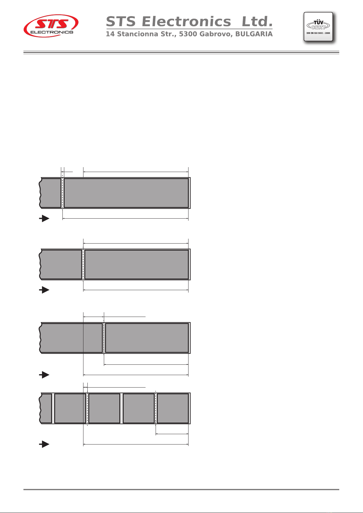
Possible variants are shown in Figure 1.
Determining the value of the parameter - Offset stop.
1. The length of the used label is longer
than L .
The offset value is 100 [mm].
2. The length of the used label and the
half of the gap are equal to L.
The offset value is 100 [mm].
3. The length of the used label is
smaller than L. The offset value is
determined by subtracting the length of
the label and half of the gap from 100
[mm].
4. The length of the used label is several
times smaller than L. The offset value is
determined by subtracting the sum of all
insertable labels and gaps from 100
[mm] and adding half of the gap.
Note: Measured offset results are a
good start. Several adjustments may be
needed to more accurately position the
beginning of the label.
Label
Label
LabelLabel
Label Label Label Label
Label
Label
1.
2
3.
> 100mm
Offset stop = 100mm
Offset stop = 100mm
= 100mm
Offset stop
Offset stop
100mm
<< 100mm
< 100mm
100mm
L0
.
4.
fig.1
V.2.00STS808
phone: (+359) 66 801 536 fax: (+359) 801 547
[email protected] www.stselectronics.eu

- 10 -
V.2.00STS808
Application 2.
Determining the value of the parameter - Distance
between labels
L3 = ( ( D*3,14 - L1 - L2 ) / 2 ) /10 [сm]
L3
L1L2
L3
D
length
front label
length
rear label
length between labels
Container/bottle, jar .../
Front Label
Rear Label
Example:
For a container of 73 mm diameter and a label length of 85 mm and 55 mm
respectively, the distance between labels is as follows:
L3 = ((73 * 3,14 - 85 - 55) / 2) / 10 [cm]
L3 = 4.461 [cm].
Enter the value rounded to the second character: 04,46 [cm].
L1 - length front label [mm]
L2 - length rear label [mm]
L3 - length between front and rear label [сm]
D - diameter of the container [mm]
phone: (+359) 66 801 536 fax: (+359) 801 547
[email protected] www.stselectronics.eu

L0
2
3
Offset Stop 1 = 100mm
= 100mm
Offset Stop 1
Offset Stop 1
100mm
<< 100mm
< 100mm
100mm
Label
back
Label
back
Label
back
Label
front
Label
front
Label
front
1
> 100mm
Offset Stop 1 = 100mm
Label
back
Label
front
4
- 11 -
Application 3.
The sensor which detect the end of the label is on 100mm/ L / before peeling edge
and its position can not be changed. This requires the Offset Stop 1 parameter to be entered
the value of which varies depending on the length of the label. Offset Stop 1 determines the
correct positioning of the beginning of a subsequent back label to the peeling edge. The
measurement need to be done from the beginning of the back label.
Possible variants are shown in Figure 2.
Determining the value of the parameter - Offset stop 1.
1. The length of the used label is longer
than L .
The offset value is 100 [mm].
2. The length of the used label and the
half of the gap are equal to L.
The offset value is 100 [mm].
3. The length of the used label is
smaller than L. The offset value is
determined by subtracting the length of
the label and half of the gap from 100
[mm].
4. The length of the used label is several
times smaller than L. The offset value is
determined by subtracting the sum of all
insertable labels and gaps from 100
[mm] and adding half of the gap.
Note: Measured offset results are a
good start. Several adjustments may be
needed to more accurately position the
beginning of the label.
fig. 2
V.2.00STS808
phone: (+359) 66 801 536 fax: (+359) 801 547
[email protected] www.stselectronics.eu

- 12 -
V.2.00STS808
Application 4.
Determining the value of the parameter - Offset stop 2.
1
2
3
> 100mm
Offset Stop 2 = 100mm
Offset Stop 2 = 100mm
= 100mm
Offset Stop 2
Offset Stop 2
100mm
<< 100mm
< 100mm
100mm
Label
front
Label
back
Label
back
Label
back
Label
front
Label
front
Label
front
Label
back
Label
front
4
L0
fig.3
The sensor which detect the end of the label is on 100mm/ L / before peeling edge
and its position can not be changed. This requires the Offset Stop 2 parameter to be entered
the value of which varies depending on the length of the label. Offset Stop 2 determines the
correct positioning of the beginning of a subsequent back label to the peeling edge. The
measurement need to be done from the beginning of the back label.
Possible variants are shown in Figure 3.
1. The length of the used label is longer
than L .
The offset value is 100 [mm].
2. The length of the used label and the
half of the gap are equal to L.
The offset value is 100 [mm].
3. The length of the used label is
smaller than L. The offset value is
determined by subtracting the length of
the label and half of the gap from 100
[mm].
4. The length of the used label is several
times smaller than L. The offset value is
determined by subtracting the sum of all
insertable labels and gaps from 100
[mm] and adding half of the gap.
Note: Measured offset results are a
good start. Several adjustments may be
needed to more accurately position the
beginning of the label.
phone: (+359) 66 801 536 fax: (+359) 801 547
[email protected] www.stselectronics.eu

NOTES
V.2.00STS808
phone: (+359) 66 801 536 fax: (+359) 801 547
[email protected] www.stselectronics.eu


GENERAL CONDITIONS for usage of electronic devices:
The electronic devices are intended to be used in normal climate
conditions in an environment with a normal fire-safety, and without any
aggressive to the body material liquids and gases.
GUARANTEE CONDITIONS:
The guarantee period is 12 months from the date of selling.
The manufacturer does not take responsibility in the following cases:
- non-observance of storage conditions;
- non-observance of transport conditions;
- non-observance of operational conditions;
- natural disasters;
The guarantee is only valid if the device is mechanically intact, and there
is no sign of attempts for eliminating damage by unauthorized personnel.
Transportation expenses are on customer’s account.
Attention: No organic dissolvent agents should be used for cleaning the
front panel!
FACTORY NUMBER:_______________________________________
STS808
phone: (+359) 66 801 536 fax: (+359) 801 547
[email protected] www.stselectronics.eu
Table of contents
Other STS Industrial Equipment manuals


