Form 801817 Page Number - 3
Introduction
The Mityvac Fuel Injection Cleaner can perform
two types of engine cleaning services:
1. Fuel Injector Cleaning
2. Air Induction System Cleaning
Fuel Injector Cleaning is performed by installing
the Cleaner directly into the fuel delivery system,
where it dispenses a specially formulated solution
directly into the engine. The solution dissolves
deposits from the injectors and prevents future
buildup.
Air Induction System Cleaning is performed by
inserting a nozzle (sold separately) into the air
intake stream. The Cleaner delivers cleaning
solution to the nozzle under pressure, where it
is injected into the air stream as a fine mist. The
solution coats the inside of the throttle body,
intake manifold, and valves, to loosen and
dissolve carbon deposits. The deposits are then
burned off by engine combustion.
Both types of cleaning services can enhance
engine performance, improve fuel economy,
reduce maintenance and improve emissions.
Application Precautions
This equipment is intended for use by vehicle
service professionals with experience and knowl-
edge of its application and limitations. While it is
designed for servicing a variety of vehicles in a
safe and convenient manner, due to variations
between vehicle manufacturers, makes, models
and years, use of this equipment is not always
feasible, possible, or recommended.
Use common sense when operating this equip-
ment. If something does not seem or feel right,
stop immediately and consult a professional with
knowledge of the application. Don’t force the use
of this equipment on an application for which it is
not intended.
The procedures documented in this manual
are to serve as guidelines for general use of
this equipment. In addition to these guidelines,
always follow the vehicle manufacturer’s recom-
mended procedures when attempting to use this
equipment.
When installing this equipment for induction
system cleaning, insure the cleaning solution is
introduced downstream from the mass airflow
sensor. Installing the nozzle upstream of the sen-
sor can cause permanent damage to the sensor.
Harsh cleaning solutions can damage some
delicate idle air control valves. If unsure of the
effect of the cleaning solution on the IAC for the
vehicle, consult the vehicle’s manufacturer for
further information.
When performing a fuel injector cleaning service,
keep the Cleaner pressure below the rated fuel
pressure of the vehicle to prevent damage to the
injectors, and to prevent cleaning solution from
bypassing the regulator and entering the fuel
tank.
Safety Precautions
• Carefully read and understand these
instructions prior to using this equipment
• Always wear safety glasses when using this
equipment
• Avoid burns by remaining cautious of engine
parts that may become hot when the engine
is running
• Operate the vehicle only in a well ventilated
area, and away from potential sources of
flame or ignition
• Prior to starting an engine, make sure all
components of the tester, body parts, and
personal clothing are clear of rotating engine
components.
• Never leave a vehicle unattended during the
cleaning process.
• Check and secure all fuel system connec-
tions before starting the vehicle or pressur-
izing the system.
• Always keep a fire extinguisher on hand
when performing fuel related procedures.
Make sure the extinguisher is rated for fuel,
electrical, and chemical fires.
• Protect painted surfaces from fuel and
cleaning solutions.
• Release fuel system pressure before
servicing or disconnecting any fuel system
related components.
• This system is designed for use on gasoline
systems only.
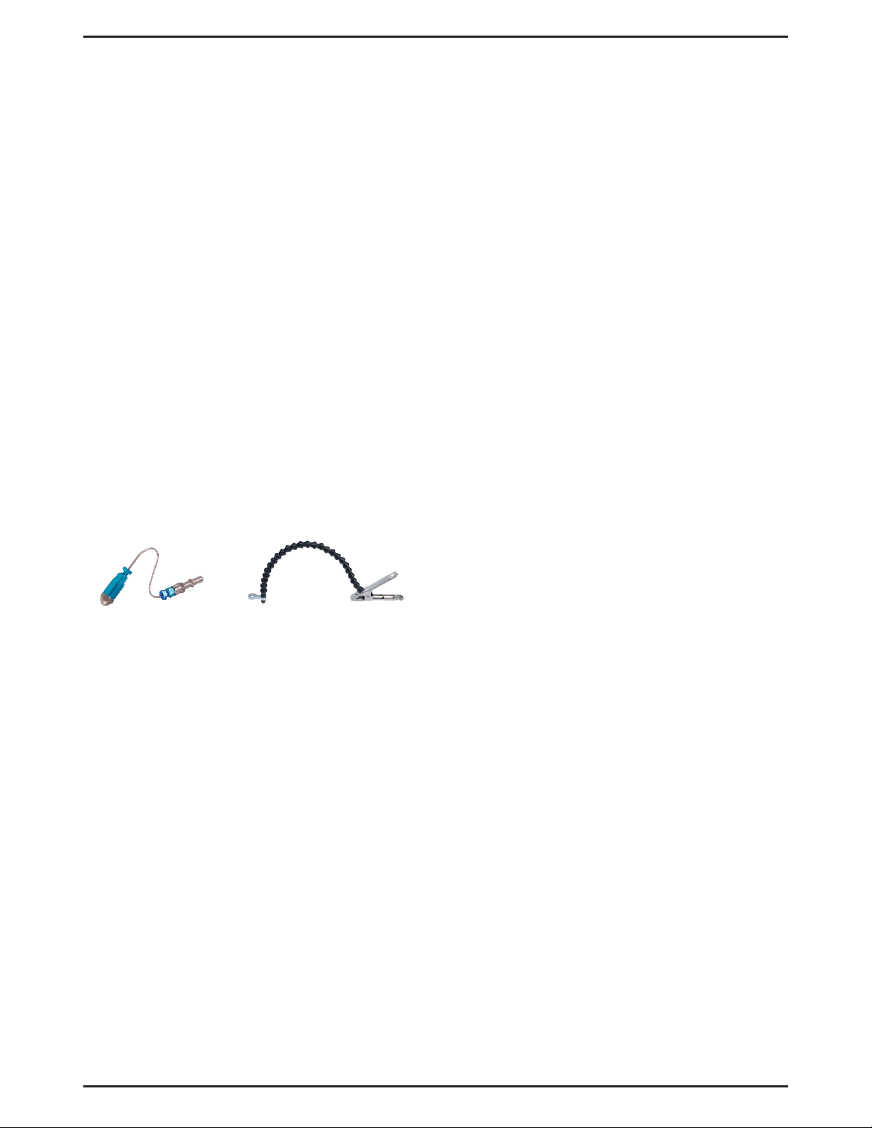
MVA550 - Decarb Nozzle MVA551 – Extended Nozzle Clamp