MKN Combisteamer TKECOD610T User manual

Installation instructions
Combisteamer
Unit Type of energy Unit type Model
SpaceCombi Magic
Team
Electric Floor-standing unit TKECOD610T
Translation from the original document • 4127002--0AIDE-C • 06/04/2020
4127002--0AIBE-C en-GB
Read the operating instructions prior to
commissioning

2 Installation instructions
Manufacturer
MKN Maschinenfabrik Kurt Neubauer GmbH & Co. KG
Halberstädter Straße 2a
38300 Wolfenbüttel
Germany
Phone +49 5331 89-0
Fax +49 5331 89-280
Internet www.mkn.com
Copyright
All rights to text, graphics and pictures in this documentation are held by MKN Maschinenfabrik Kurt
Neubauer GmbH & Co. KG. Distribution or duplication is only permitted with the prior written consent
of MKN.
Copyright by MKN Maschinenfabrik Kurt Neubauer GmbH & Co. KG.

Directory of contents
3Installation instructions
1Introduction......................................................................... 5
1.1About this manual ............................................................................ 5
1.1.1Explanation of signs .................................................................................. 6
1.2Staff qualification ............................................................................. 7
1.3Use of the unit................................................................................... 7
1.4Warranty............................................................................................ 7
2Safety information.............................................................. 8
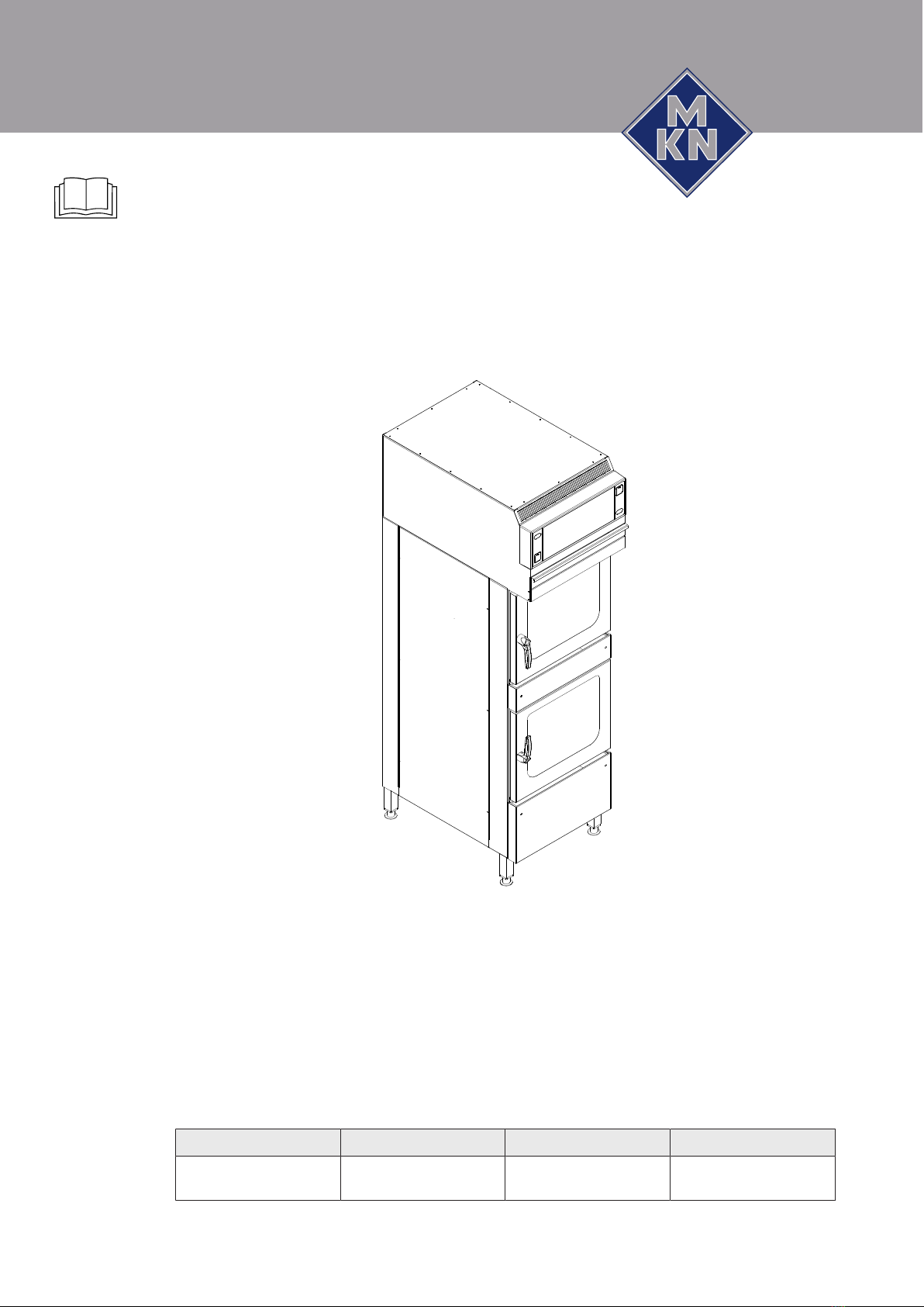
3Description of the unit ..................................................... 10
3.1Overview of the unit ....................................................................... 10
3.2Equipment and connection data................................................... 11
4Transporting the unit ....................................................... 16
4.1Transporting the unit to the installation site ............................... 16
4.2Unpacking the unit ......................................................................... 17
5Setting up the unit............................................................ 18
5.1Minimum clearances ...................................................................... 19
5.2Lifting the unit off the pallet .......................................................... 19
5.3Placing the unit on the equipment legs........................................ 20
5.4Aligning the unit ............................................................................. 20
5.5Checking the filter on the air recirculation hood......................... 21
5.6Fastening the unit to the floor....................................................... 22
5.6.1Securing the unit against tilting ............................................................... 22
6Connecting the unit.......................................................... 25
6.1Opening and closing the housing................................................. 25
6.1.1Removing and attaching the rear panel .................................................. 25
6.2Making the electrical connection.................................................. 26
6.2.1Connecting the power connection cable ................................................. 28
6.2.2Connecting the power optimizing system................................................ 29
6.2.3Connecting to the potential equalisation circuit ....................................... 30
6.3Connecting the kitchen management system ............................. 31
6.4Making the basic control setting................................................... 32
6.4.1Changing the basic control setting .......................................................... 32
6.5Making the water connection ........................................................ 33
6.5.1Connecting the tap water connection line ............................................... 34
6.5.2Connecting softened tap water to both connections ............................... 35
6.6Making the wastewater connection .............................................. 35
6.6.1Connecting the wastewater line to a permanent connection................... 36
6.6.2Connecting wastewater line to collection basin (optional)....................... 37
7Checking operation.......................................................... 38
7.1Checking the air recirculation hood ............................................. 38
4127002--0AIBE-C

Directory of contents
4 Installation instructions
7.2Checking the controls.................................................................... 38
7.3Checking the monitoring of the cooking zone door ................... 39
7.4Heating the unit up and rinsing it out........................................... 39
8Putting the unit into service ............................................ 40
8.1Nameplate ...................................................................................... 40
8.2Filling out the commissioning report ........................................... 41
4127002--0AIBE-C

Introduction
5Installation instructions
1 Introduction
1.1 About this manual
The instruction manual is part of the unit and contains information on
safe installation of the unit.
Observe and adhere to the following instructions:
•Read the instruction manual in its entirety prior to installation.
•Make the instruction manual available to the installer at the
operating site at all times.
•Preserve the installation manual throughout the service life of the
unit.
•Insert any supplements from the manufacturer.
•Pass on the installation manual to any subsequent operator of the
unit.
Target group The target group for the installation manual is trained technical
personnel that is familiar with installing and operating the unit.
Figures All figures in this manual are intended as examples. Discrepancies
between these and the actual unit can arise.
4127002--0AIBE-C

Introduction
6 Installation instructions
1.1.1 Explanation of signs
DANGER
Imminent threat of danger
Failure to comply will lead to death or very severe injuries.
WARNING
Possible threat of danger
Failure to comply can lead to death or very severe injuries.
CAUTION
Dangerous situation
Failure to comply can lead to slight or moderately severe
injuries.
ATTENTION
Physical damage
Failure to comply can cause physical damage.
Notes for better understanding and operation of the unit.
Symbol / sign Meaning
•Listing of information.
Action steps, which can be performed
in any sequence.
1.
2.
Action steps, which must be performed
in the specified sequence.
Result of an action performed or
additional information about it.
4127002--0AIBE-C

Introduction
7Installation instructions
1.2 Staff qualification
Explanation of qualification
Skilled staff •Skilled staff are those, who due to their profes-
sional training, knowledge and experience as well
as their knowledge of the relevant standards can
assess the tasks given to them and recognize any
possible dangers.
Type of activity Qualification
Power connection •Electrician
•Specific professional training
•Employee of the specialist company concerned
Water connection •Plumber
•Specific professional training
•Employee of the specialist company concerned
Wastewater connection •Wastewater specialist
•Specific professional training
•Employee of the specialist company concerned
1.3 Use of the unit
This unit is intended to be used solely for commercial purposes,
particularly in commercial kitchens.
The use of the unit is prohibited in the following countries:
•USA
•Canada
1.4 Warranty
The warranty is void and safety is no longer assured in the event of:
•Improper conversion or technical modifications of the unit,
•Improper use,
•Incorrect startup, operation or maintenance of the unit,
•Problems resulting from failure to observe these instructions.
4127002--0AIBE-C

Safety information
8 Installation instructions
2 Safety information
The unit complies with applicable safety standards. Residual risks
associated with operation or risks resulting from incorrect operation
cannot be ruled out and are mentioned specifically in the safety
instructions and warnings.
The installer must be familiar with regional regulations and observe
them.
The installer must observe the safety instructions in these mounting
instructions and in the "Safety information" chapter of the operating
instructions.
Ensuring conformity with
standards
Observe applicable international, European and national laws,
regulations, standards and directives for the unit when transporting,
setting up and connecting it.
Improper installation Risk of property damage and personal injury from improper
installation
•Install the unit only as specified in these installation instructions.
•Do not add anything to the unit or modify the unit.
•Use only original spare parts.
Transportation and storage Risk of personal injury and property damage from improper
transportation and improper storage
•Store the unit in a dry, frost-free environment.
•Observe the safety regulations for the lifting gear used.
•Attach the unit to the lifting gear securely during transport and
setup, and prevent it from dropping.
•Transport the unit in an upright position, do not tilt or stack.
•Pay attention to protruding parts when transporting the unit
without packaging.
Fire prevention Risk of fire from combustible surfaces
•Observe general fire prevention regulations.
Organisational measures Risk of property damage and personal injury from lack of
organizational measures
•Identify hazard areas when transporting, setting up and
connecting the unit.
•Prior to starting the installation work, notify any operators present
about the procedure.
•Prior to starting the installation work, discuss how to behave in an
emergency.
•Use equipment and protective gear suitable for the activity.
•Brace housing components to prevent them from falling over and
dropping.
4127002--0AIBE-C

Safety information
9Installation instructions
Setup Risk of property damage and personal injury from improper
setup
•Ensure that the installation area has adequate load-bearing
capacity.
•Wear safety shoes and protective gloves.
Electrical connection Risk of fire from improper connection
•Observe applicable regional regulations of the electrical utility.
•Ensure that only electricians licensed by the electric utility connect
the unit.
•Ensure that the electrical system is earthed by a protective
earthing conductor.
•Note the information on the nameplate.
Risk of electric shock from live components.
•Prior to working on the electrical system, switch off the unit,
disconnect the electrical system from the mains and prevent
power from being switched on again. Check to ensure absence of
voltage.
•Use only insulated tools.
Commissioning Risk of property damage and personal injury from improper
commissioning
•Read the operating instructions prior to commissioning. Observe
the safety instructions in this installation manual and in the "Safety
information" chapter of the operating instructions.
•Put the unit into service only after a successful function test
following assembly.
•Put the unit into service only after it has reached room
temperature.
•Observe the units during operation.
4127002--0AIBE-C

Description of the unit
10 Installation instructions
3 Description of the unit
3.1 Overview of the unit
a
b
c
d
e
f
g
h
i
j
k
l
m
n
o
p
q
Image: Floor-standing unit
a Air outlet j Equipment leg
b Control unit k Nameplate
c Filter drawer l Discharge channel for bottom unit
d Condensate baffle m Cooking zone in bottom unit
e Support rack n Discharge channel for top unit
f Door handle o Cooking zone in top unit
g Discharge channel for top door p Housing
h Cooking zone door q Air recirculation hood
i Discharge channel for bottom
door
4127002--0AIBE-C

Description of the unit
11Installation instructions
3.2 Equipment and connection data
Size 610
Dimensions
Unit
Length x Width x Height (mm)
550 x 880 x 1908
Due to construction minimum
distance between unit and wall
(mm)
70
Weight
Unit ≈ (kg) 220
Emissions
Sound level (db(A)) < 65
Steam output (g/h) 1240
Steam output (m³/h) 2,1
Latent heat (W) * 842
Sensible heat (W) * 1872
The sensible and latent heat amounts are determined in Germany on the basis of VDI 2052 at a connection voltage of
400V. Regulations applying in other regions may vary from this.
Operating environment
Temperature (°C) 5 — 40
Relative humidity (%)
non-condensing
95
Power connection
Protection class IPX5
Connection terminal (mm²) 6
Connection line One connection line Two connection lines
Information per connection line
Type of connection 3PE AC 50/60Hz, 3NPE AC 50/60Hz
Voltage (V) 200
Connected load (kW) 14 7
Fuse (A) 50 25
Voltage (V) 208
Connected load (kW) 14.8 7.4
Fuse (A) 50 25
Voltage (V) 220
Connected load (kW) 16.8 8.4
Fuse (A) 50 25
Voltage (V) 230
Connected load (kW) 18.2 9.1
Fuse (A) 50 25
Voltage (V) 240
4127002--0AIBE-C

Description of the unit
12 Installation instructions
Size 610
Connected load (kW) 19.6 9.8
Fuse (A) 50 25
Voltage (V) 380
Connected load (kW) 14.8 7.4
Fuse (A) 25 16
Voltage (V) 400
Connected load (kW) 15.6 7.8
Fuse (A) 25 16
Voltage (V) 415
Connected load (kW) 16.2 8.1
Fuse (A) 25 16
Voltage (V) 440
Connected load (kW) 15.8 7.9
Fuse (A) 25 16
Type of connection 2PE AC 50/60 Hz
Voltage (V) 208
Connected load (kW) 10.6 5.3
Fuse (A) 63 35
Voltage (V) 240
Connected load (kW) 13.8 6.9
Fuse (A) 63 35
Type of connection 1NPE AC 50/60 Hz
Voltage (V) 220
Connected load (kW) 11.6 5.8
Fuse (A) 63 35
Voltage (V) 230
Connected load (kW) 12.8 6.4
Fuse (A) 63 35
Voltage (V) 240
Connected load (kW) 13.8 6.9
Fuse (A) 63 35
Power optimizing system
Connection terminal (mm²) 2,5
Softened tap water connection
Water type Softened tap water, cold
Carbonate hardness CaCO3
(mmol/l (°dH))
< 0,9 (5)
Chloride Cl (mg/l) < 100
4127002--0AIBE-C

Description of the unit
13Installation instructions
Size 610
Iron FE (mg/l) < 0.2
Connection pressure (kPa (bar)) 200 (2) — 600 (6)
Connection (") R 3/4 male thread
Tap water connection
Water type Tap water, cold
Carbonate hardness CaCO3
(mmol/l (°dH))
< 4 (22,2)
Connection pressure (kPa (bar)) 200 (2) — 600 (6)
Connection (") R 3/4 male thread
Water consumption for steaming *
Softened tap water (l/h) 20
Water consumption for Combisteaming *
Softened tap water (l/h) 4,4
Water consumption for WaveClean cleaning program *
Softened tap water (l) 2,5
Tap water (l) 35
Wastewater connection
Wastewater type Dirty water, maximum 80 °C
Maximum length (m) 1 with a drop of at least 5% or 3°
Temperature resistance (°C) 95
Connection (mm) 50
Maximum volume flow (l/min) 10
* Applies to both cooking zones together
Floor fastening
Mandatory for the following types of unit
TKECOD610 Only for unit with castors
4127002--0AIBE-C

Description of the unit
14 Installation instructions
Basic control setting
Basic setting Parameter
s
Standard
value
Adjustment
range
Explanation
Actual voltage 14 400 100 — 500V Set the local, mean voltage between the
line conductors.
Date/time yyyy - mm - dd Year - Month - Day
hh : mm Hour : Minute
Altitude 2 0—999 0—999 m Request the altitude above sea level from
the closest weather station. If the altitude
is unknown, set 0—999 m.
1000 m—1999
m
2000 m—2499
m
2500 m or higher
Volume of audible
signal
Medium Individual Sets the volume.
Temperature unit
setting
1 °C °C Celsius (°C)
°F Fahrenheit (°F)
Unit of volume 34 ml (ml) Millilitre (ml)
(fl.oz.) Fluid ounce (fl.oz.)
35 Imperial
(fl.oz.)
Imperial (fl.oz.) Imperial fluid ounce
U.S. (fl.oz.) U.S. fluid ounce
Water filter
maintenance
44 0 0 — 99900 l Water quantity up to the maintenance
message.
0 = No maintenance message
Network DHCP Network address
and DHCP
Select and set interface.
Kitchen control
system
652 Disabled 0 = Disabled
1 = Active
Indicates whether the Kitchen
management system is being used.
659 Ethernet 0 = Ethernet
1 = Serial
Type of signal transmission (interface)
653 1188 0 — 65535 TCP port setting
654 254 0 — 254 Unit address
80% power 3 100 80 % Power can be limited to 80% (for special
applications).
100 %
Power optimisation
system
42 Off On If a power optimisation system is
connected, "On" must be selected for the
unit to heat.
Off
Settings parameters 1. Set parameters via the roller.
2. Tap the "Read" button to display the
set value.
3. Specify another value via the button
panel.
4. Press the "Write" button to save the
new value.
4127002--0AIBE-C

Description of the unit
15Installation instructions
Basic control setting (Advanced)
Basic setting Parameter
s
Standard
value
Adjustment
range
Explanation
Generator operation 45 0 0 = No If a generator is used to supply electricity
1 = Yes
Vapour elimination 48 1 0 = Low Sets the vapour elimination level
1 = Normal
2 = High
Time format 675 0 0 = 24h Sets the 12h or 24h time format
1 = 12h
Format for cooking
program times
676 0 0 = hh:mm
1 = mm:ss
2 = Automatic
Display format for cooking program times
4127002--0AIBE-C

Transporting the unit
16 Installation instructions
4 Transporting the unit
CAUTION
Risk of property damage and personnel injury from tipping
equipment
• Do not linger next to or behind raised equipment.
• Move raised equipment carefully.
ATTENTION
Risk of physical damage from improper transport
• Transport the unit upright.
• Do not tilt or stack the unit.
• Pay attention to protruding parts when transporting the
unpacked unit.
Prior to transporting the unit to the installation site, ensure that:
•The roadway has adequate load-bearing capacity.
•Wall openings are large enough.
4.1 Transporting the unit to the installation site
Image: Lengthwise and crosswise transport on pallet
Use suitable transport means to move the unit to the installation
site.
4127002--0AIBE-C

Transporting the unit
17Installation instructions
4.2 Unpacking the unit
CAUTION
Risk of injury from sharp edges
• Wear protective gloves.
When unpacking the unit, inspect it for transport damage.
Do not install damaged units or put into service.
1. Remove the packaging.
2. Pull the protective film off the unit.
3. Remove the packaging material from the cooking zone
completely.
4. Clean the unit (See Operating instructions).
5. Enter the information from the nameplate into the Commissioning
report.
6. Enter the information from the nameplate into the Operating
instructions.
4127002--0AIBE-C

Setting up the unit
18 Installation instructions
5 Setting up the unit
CAUTION
Risk of crushing from improper setup
• Protect the unit and work area during setup and alignment.
CAUTION
Risk of fire from failure to observe applicable regional fire
prevention regulations
• Observe applicable regional fire prevention regulations.
ATTENTION
Risk of physical damage from overheating of the unit
• Do not set up the unit close to heat sources.
ATTENTION
Risk of physical damage from lifting the unit by the
discharge channels
The discharge channels may become deformed
• Do not lift or support the unit by the discharge channels.
4127002--0AIBE-C

Setting up the unit
19Installation instructions
5.1 Minimum clearances
A
CB
D
Image: Minimum clearances to walls, ceiling or units
A B C * D
--- 100 50 ---
All dimensions in mm
* Depending on the kitchen ventilation system and the material composition of the
ceiling
The following clearances from walls, ceilings or other equipment must
be maintained when installing the unit:
•Clearance to deep-fat fryers, at least one length of the hand
shower on the left and right.
5.2 Lifting the unit off the pallet
CAUTION
Risk of property damage and personnel injury from tipping
equipment
• Do not linger next to or behind raised equipment.
• Move raised equipment carefully.
Requirements Unit unpacked
Protective film removed
Unit cleaned
1. Slide the forks of the pallet truck under the unit.
2. Lift the unit carefully off the pallet.
4127002--0AIBE-C

Setting up the unit
20 Installation instructions
5.3 Placing the unit on the equipment legs
Requirement The floor must support the weight of the unit
1. Use appropriate lifting gear to lift the unit.
2. Set up the unit in accordance with the planning drawing.
3. Align the unit lengthwise and crosswise (see "Aligning the unit").
5.4 Aligning the unit
Image: Aligning the unit on the equipment legs
1. Place a spirit level on the unit.
2. Align the unit horizontally by screwing the equipment legs in or
out.
3. Fill out the Commissioning report.
4127002--0AIBE-C
Table of contents
Other MKN Kitchen Appliance manuals

MKN
MKN TKECOD610O User manual

MKN
MKN OPEHEV4EB User manual

MKN
MKN OPGHEG1 Series User manual

MKN
MKN FlexiCombi Classic Series User manual

MKN
MKN FlexiCombi MagicPilot 6.15 Technical manual

MKN
MKN OPEHED Series User manual

MKN
MKN OPGHED4GB User manual

MKN
MKN FlexiCombi MagicPilot FKECOD615 User manual

MKN
MKN SpaceCombi Compact MagicPilot User manual

MKN
MKN FlexiCombi MagicPilot FKGCOD615T User manual