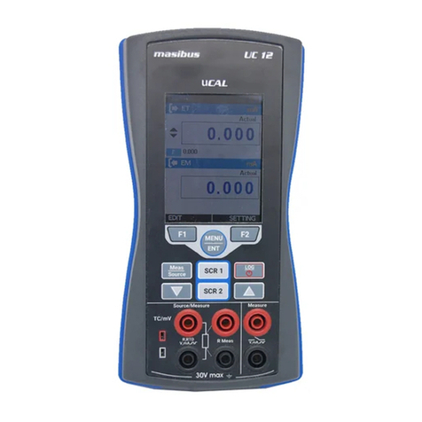
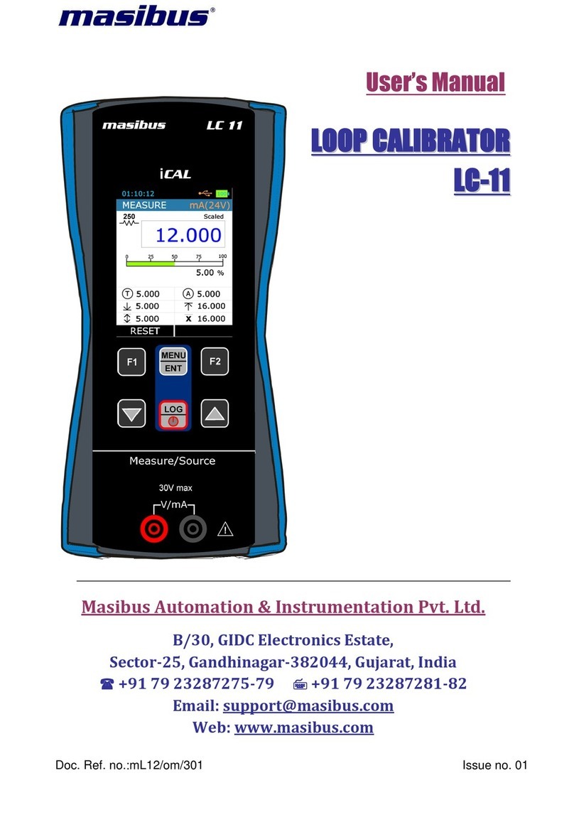
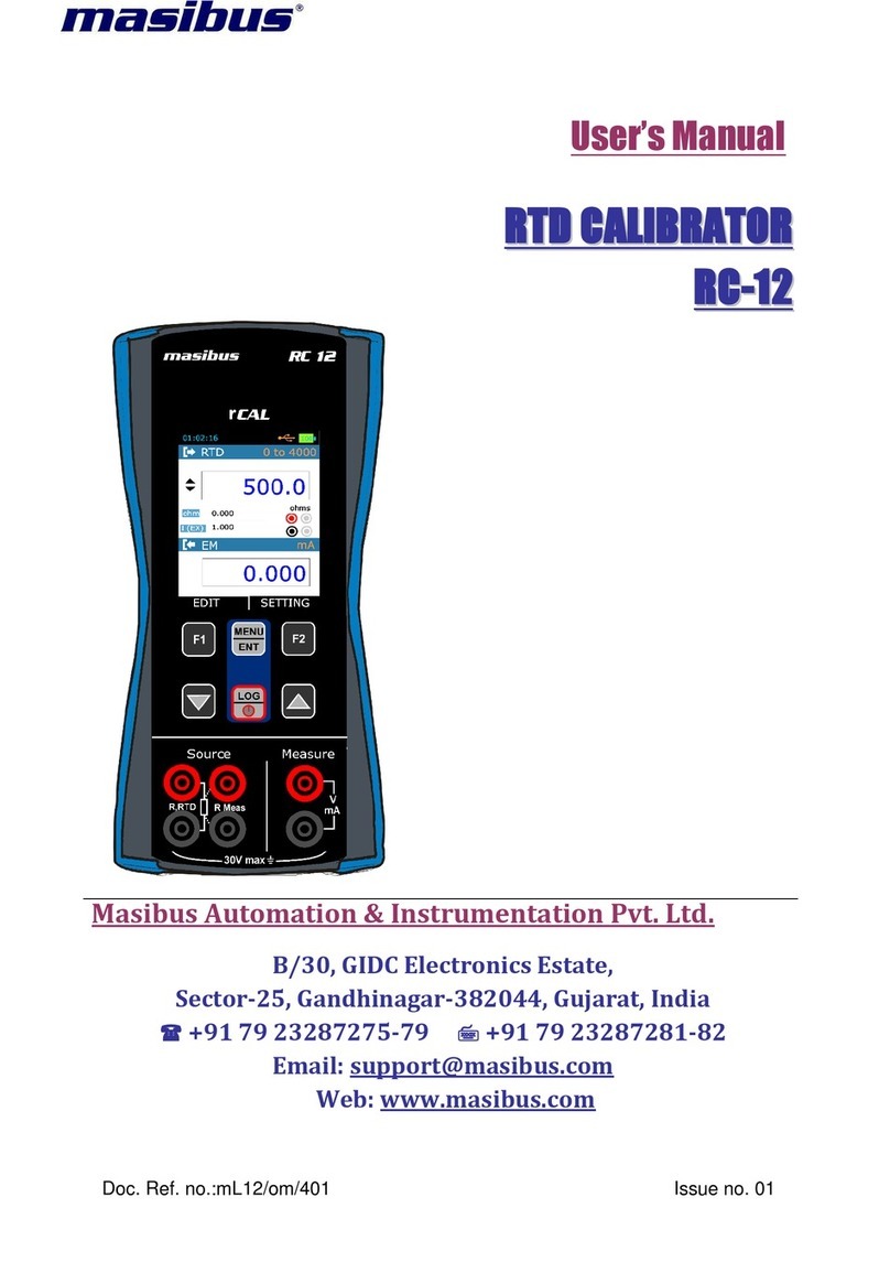
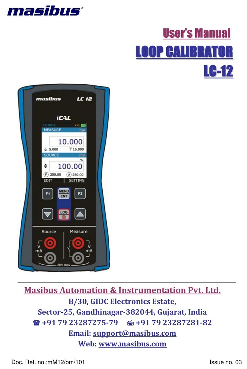
Masibus PCE-MCA 50 User manual

User’s Manual
UNIVERSAL CALIBRATOR
PCE-MCA 50
PCE Instruments
Email: [email protected]
Web: http://www.pce-instruments.com
Doc. Ref. no.:mM12/om/201 Issue no. 00

Contents
1. Introduction ......................................................................................................4
Foreword.......................................................................................4
Notice............................................................................................4
Trademarks...................................................................................4
Safety ............................................................................................4
General warnings.........................................................................5
Electrical warnings.......................................................................5
Cautions........................................................................................5
Summary of functions..................................................................6
2. PCE-MCA 50 Hardware Parts & Accessories.................................................7
2.1 Unpacking & Inspection.......................................................7
2.2 Operational Sections and Connections..............................8
2.2.1 The Terminal Connections ...........................................8
2.2.2 The KeyPad ...............................................................17
2.2.3 The Display................................................................18
2.2.4 The USB Connection..................................................18
2.2.5 Stand for Table Top Use ............................................18
2.3 Power Options....................................................................19
2.4 Battery.................................................................................19
2.4.1 Charge time.................................................................19
2.4.2 Operating Time ..........................................................20
3. Start Up & Basic Operations .........................................................................21
3.1 Power ON or OFF..................................................................21
3.2 The User Interface................................................................21
3.2.1 The Status Bar...........................................................22
3.2.2 The Function key Bar.................................................23
3.2.3 Display Mode .............................................................23
3.2.4 Display Operations.....................................................30
3.2.5 SCR1 and SCR2 Key Option : mQUICK-SETUP Key 35
4. Menu Layout...................................................................................................36
4.1 MENU page .........................................................................36

4.2 MEASURE Page..................................................................36
4.3 SOURCE Page ....................................................................38
4.3.1 ET Setup......................................................................38
4.3.2 TC Setup......................................................................44
4.3.3 RTD Setup...................................................................47
4.3.4 Pulse Setup..................................................................53
4.4 DISPLAY Page ......................................................................54
4.4.1 EM Display Settings.....................................................56
4.4.2 Switch test Display Settings .........................................57
4.4.3 ET Display Settings......................................................58
4.4.4 TC Display Settings......................................................59
4.4.5 RTD Display Settings...................................................61
4.5 DATA LOGGING Page..........................................................63
4.5.1 Transferring the Results to a Personal Computer:......65
4.6 CJC SETTING Page..............................................................66
4.7 Wire Select Page ..................................................................67
4.8 Alarm Page............................................................................68
4.9 SETTING Page ....................................................................69
4.9.1 HART Settings ...........................................................69
4.9.2 Display Settings .........................................................70
4.9.3 Date/Time Settings.....................................................70
4.9.4 Calibration..................................................................71
4.9.5 Battery Info.................................................................71
4.9.6 Set Password.............................................................71
4.9.7 Factory Reset.............................................................72
4.9.8 About Us....................................................................72
5. Maintenance & Troubleshooting...................................................................72
5.1 Common Problems.............................................................72
5.2 Replacing the Battery.........................................................73
5.3 Related Information............................................................73
5.3.1 Thermocouple Measurement/Simulation, Connections and
troubleshooting. ....................................................................74
5.3.2 Parallel Functions in PCE-MCA 50...............................76
6. General Specifications...................................................................................77
6.1 General Specifications.........................................................78

6.2 Display & Keys .....................................................................78
6.3 Special Features...................................................................78
6.4 Power Supply........................................................................79
6.5 Physical.................................................................................79
6.6 Electrical Measurement Parameters and Accuracy..........79
6.7 Electrical Simulation Parameters and Accuracy................80
6.8 Resistance Measurement 0 ... 4000 ohm ............................80
6.9 Resistance Simulation 0 ... 4000 ohm.................................80
6.10 RTD Measurement and Simulation....................................81
6.11 Available RTD Types..........................................................81
6.12 Thermocouple/mV Resolution and Accuracy...................82
6.13 Frequency Measurement ...................................................82
6.14 Pulse counting....................................................................82
6.15 Frequency Generation .......................................................82
6.16 Pulse Generation................................................................83
6.17 Enclosure Dimensions.......................................................84

1. Introduction
Foreword
Thank you for purchasing Universal Calibrator PCE-
MCA 50. The PCE-MCA 50 calibrator is compact hand-
held calibrator with an easy to use graphical user
interface.
This manual describes the basic functions and operation
methods. Please read through this user’s manual
carefully before using the product.
Notice
The contents of this manual are subject to change
without notice as a result of continuous improvements
to the instrument’s performance and functions.
Every effort has been made to ensure accuracy in the
preparation of this manual. Should any errors or
omissions come to your attention, however, please
inform PCE INSTRUMENTS Sales office or sales
representative. Under no circumstances may the
contents of this manual, in part or in whole, be
transcribed or copied without our permission.
Trademarks
Our product names or brand names mentioned in this
manual are the trademarks or registered trademarks of
PCE INSTRUMENTS (Herein after referred to as PCE
INSTRUMENTS).
Adobe, Acrobat, and Postscript are either registered
trademarks or trademarks of Adobe Systems
Incorporated. All other product names mentioned in this
user's manual are trademarks or registered trademarks
of their respective companies.
Safety
Before you use the instrument, make sure that you read
and understand all the related data. This includes: the
applicable local safety procedures, this publication,
and the instructions for the
accessories/options/equipment you are using it with.

General
warnings
WARNING
It is dangerous to ignore the specified limits
for the instrument or its related accessories.
Do not use the instrument or accessory if it is
not in its normal condition.
Use the applicable protection and obey all
safety precautions.
Do not use the instrument in locations with
explosive gas, vapor or dust. There is a risk
of an explosion
Electrical
warnings
To prevent electrical shocks or damage to the
instrument, do not connect more than 30V
between the terminals, or between the terminals
and the ground.
This instrument uses a Lithium-Ion battery pack.
To prevent an explosion or fire, do not short
circuit, do not disassemble, and keep it safe
from damage. For operating conditions, see
section 6.1 on Page-85
To prevent battery leakage or heat generation,
only use the battery charger in the temperature
range 0 to 45°C (32 to 113°F). For operating
conditions, see section 6.1 on Page-85.
To make sure the display shows the correct
data, disconnect the test leads before you set
the power to on or change to another measure
or source function.
Cautions
To prevent damage to the display, do not use
sharp objects on the screen.
Before you start an operation or procedure in this
publication, make sure that you have the
necessary skills (if necessary, with qualifications
from an approved training establishment). Follow
good engineering practice at all times.

Summary of
functions
This table gives a summary of the available functions
with the PCE-MCA 50 calibrator.
Function
Easy to read liquid crystal display (LCD) in color
Rechargeable lithium Ion battery with enhanced power control
for prolonged battery life.
* Measure RTD(Pt10, Pt50, Pt100, Pt200, Pt400, Pt1000,
Pt100(3926),Ni100(672), Ni100(618), Ni120(672), Cu10(427),
Cu50(427), Cu100(427)), Resistance (0 to 4000 ohms), mA,
mA(2W), V,Thermocouple (E,J,K,T,B,R,S,N), mV(-10 to
250mV),Switch-test, Frequency, Pulse
* Simulate RTD(Pt10, Pt50, Pt100, Pt200, Pt400, Pt1000,
Pt100(3926),Ni100(672), Ni100(618), Ni120(672), Cu10(427),
Cu50(427), Cu100(427)), Resistance (0 to 4000
ohms),Thermocouple (E,J,K,T,B,R,S,N), mV(-10 to 250mV), mA,
mA(2W), V, Frequency, Pulse
Step/Ramp functions: Automatic/Manual
Universal Serial Bus (USB) communications ports: For computer
Communications, Battery Charging& Firmware Upgrade
Data Logging
Other functions:
Maximum / Minimum / Average, filter, tare, adjustable backlight,
alarm indication (on the display and buzzer), Glance Screen.
Continuity Test, Automatic / Manual Wire Selection for RTD
Measurement, RTD CJ Compensation.
* Refer to the Specification Sheet on Page: 79

2. PCE-MCA 50 Hardware Parts & Accessories
2.1 Unpacking & Inspection
At the factory each new PCE-MCA 50 passes a careful inspection. It should
be free of scrapes and scratches and in proper operation order upon
receipt. The receiver should, however, inspect the unit for any damage that
may have occurred during transit. If there are signs of obvious mechanical
damage, package contents are incomplete, or the instrument does not
operate according to specifications, contact the purchasing sales office as
soon as possible. The standard accessories are as follows:
If you have to return the instrument to the factory for any reason, use the
original packing whenever possible. Include a detailed description of the
reason for the return.

2.2Operational Sections and Connections
All sections and connections are presented in detail on the next pages.
Note:
Keep in mind that the next picture (as well as all pictures of PCE-MCA 50
in this manual) hasan example configuration of modules. The configuration
of your PCE-MCA 50 may vary significantly from the one in the picture.
2.2.1 The Terminal Connections
1
Terminal Connection For
Measure & Source
2
Keypad Section
3
TFT Color Display
4
USB Connection Slot for
PC Communication &
Charging

➢EM (Electric Measurements and 24V Supply) Measure Terminals
Input Terminals for measuring voltage, current, supplying loop power,
and Frequency and pulse types refer specification sheet on page no.
79 Section 6.6 and page no. 82 Section 6.13, 6.14.
•Current Measurement
PCE-MCA 50 supports current measurement using either PCE-MCA
50 as the loop power supply while at the same time measuring the
current or simply measuring the current while an external power
supply is used.
The following picture displays the connection for Current
Measurement for different mode. And also different ways of providing
the supply power to the loop.
➢mA Current Measurement
In this mode PCE-MCA 50 not providing any supply voltage.
For proper measurement the external device should capable of
providing the voltage supply. If the external device should not
capable, an external Power Supply should be connected in
series.

➢mA Read Power Current Measurement
In this mode PCE-MCA 50 works as Loop Power Supply while
at the same time measuring the current.
•Voltage Measurement
PCE-MCA 50 is capable of voltage measurement. The following
picture displays the connection for voltage measurement.
•Frequency Measurement
PCE-MCA 50 is capable of frequency measurement. The following
picture displays the connection for frequency measurement.
Also check the Trigger Level setting. There you can specify the
trigger level and whether to use a test voltage during the frequency
measurement
•Pulse Count Measurement

PCE-MCA 50 is capable to count number of pulses. The following
picture displays the connection for pulse count measurement.
Check the Trigger Level setting to specify the trigger level and
whether to use a test voltage during the pulse counting. Also check
the Trigger Edge (Rising or Falling) setting so it suits your need.

➢ET (Electrical source Terminal) Terminals
Terminals for Simulating voltage, current, supplying loop power types
refer specification sheet on page no. 79 Section 6.7
•Current Generation
In source mode PCE-MCA 50 provides the supply power to the
loop.
The following picture displays the connection for current source for
different mode.
➢mA Current Source
➢mA 2-Wire Source
•Voltage Generation
PCE-MCA 50 is capable of voltage generation the following picture
displays the connection for voltage source.

➢RTD Terminals
Terminals for measuring & simulating RTD / Ω. For RTD/Ωtypes refer
specification sheet on Page No.79- 82 Section 6.8, 6.9, 6.10, 6.11
•RTD/Resistance Source
PCE-MCA 50 is capable of RTD/Resistance generation. The
following picture displays the connection for RTD and Resistance
simulation. In RTD simulation PCE-MCA 50 mimics an RTD. The
instrument under test generates the current for the RTD
measurement.PCE-MCA 50 controls the voltage across its terminals
so that the resistance (voltage to Current ratio) corresponds to the
simulated temperature. Use of 2, 3 or 4-wire connection is up to the
receiver instrument. Use only the two leftmost terminals with every
wiring option. Connect the possible third and fourth wire according to
the Requirements of the connected instrument but use only the two
leftmost terminals.

•RTD / Resistance measurement
PCE-MCA 50 is capable of RTD/Resistance measurement. The
following picture displays the connection for RTD and Resistance
measurement.
➢2-Wire RTD Measurement
Two leftmost terminals are used in 2-wire systems. PCE-MCA
50 displays the selected wiring system in run page. PCE-MCA
50 sources current through the resistor and measure the
voltage drop across same terminals. The result is acceptable, if
the resistance of the connection wires is significantly smaller
than actual measured resistance.
➢3-Wire RTD Measurement
PCE-MCA 50 sources current through the resistor and measure
the voltage drop across the entire current loop and across the
upper side connection wire as shown in figure. If both left side
connection wires are identical, PCE-MCA 50 can compensate
for the resistance of the connection wires.
➢4-Wire RTD Measurement
PCE-MCA 50 sources current through the resistor from two left
side terminals andmeasure the voltage drop across the resistor
from the two right side terminals. The 4-wire method gives the

resistance between the terminals of the resistor; it is insensitive
to the resistance of the connection wires.
➢TC Terminals
Terminal for measuring & simulating thermocouples and mV. This
terminal accepts a miniature polarized thermocouple plug with flat, in-
line blades spaced 7.9 mm (0.312 in) center to center.
For specification refer Section 6.12
PCE-MCA 50 supports measurement and simulation of Thermocouple
and mV.
➢Frequency Terminals
PCE-MCA 50 is capable of Frequency Generation. The following
picture displays the connection for Frequency Generation.
For specification refer Section 6.15

➢Pulse Terminals
PCE-MCA 50 is capable of Pulse Generation. The following picture
displays the connection for Pulse Generation. For specification refer
Section 6.16

2.2.2 The KeyPad
PCE-MCA 50 has nine different keys. The key description is given below.
This key has different functionalities in different menu. And that
is shown on Bottom Left Part of Display.
Pulse Resetting Shortcut: The counter may be cleared (zeroed)
by long Pressing F1 key for 3 sec during Pulse Measurement
Only.
This key has different functionalities in different menu. And that
is shown on Bottom Right Part of Display.
This key is use to scroll down to the next parameter. And also
for decrementing the value of digit in Editbox.
This key is use to scroll up to the previous parameter. And also
for incrementing the value of digit in Editbox.
This Key is use for Entering into the MENU Page from Run
Page.
And Also for Saving Edited Parameter to the memory.
This key is use to log current reading in memory if device is on
Run Page& Log Mode is Manual. (In other Page than Run
Mode, this key is use to come directly to Run Page.
Long presses (Approx.2 Sec) on this key will ON-OFF the Unit.
This key is used to go in Screen 1 setup menu page.
This key is used to go in Screen 2 setup menu page.
This key is used to switch between measure and source mode
(Only applicable for T/C,mV and RTD Measure / Simulation).

2.2.3 The Display
OR
•This is a LCD with a 3.2” color display.
•The display has resolution of 240x320 pixels supporting 262K Colors.
•Refer Section 3.2.3 on Page-23for more details on Different Display
Mode and Icon Details
2.2.4 The USB Connection
•The USB Connection Connector is given at Top of the PCE-MCA 50.
It’s a USB A Male to USB mini B Male Connector.
•It is common for PC Communication & Charging the device.
•The USB cable given with the device is USB A-type Male to USB
mini B-type male.
2.2.5 Stand for Table Top Use
•This Stand would offer the best support for table top use which
gives good viewing angle when PCE-MCA 50 is
placed table top
•Procedure to Open Stand
ois being engraved on the top of the
stand. You should pull a bit first.
ois being engraved on the bottom of the
stand. Now during first pull of above you can
release this lower part easily so that you can maneuver the
stand as you like.

2.3 Power Options
There are three power options:
•Lithium-Ion battery: All the instrument functions are available with
a charged battery.
•5 V DC Charging Adaptor: It supplies power to the instrument and
charges the battery at the same time. It charges the battery when the
instrument is on or off.
•USB mini Type B connection: This charges the battery when the
instrument is off and increases the battery life when the instrument
is on. Instrument cannot be charged with USB when it is ON.
2.4Battery
The Device uses 3000mAh Lithium-Ion
Battery. Explosion or fire, do not short
circuit, do not disassemble, and keep it
safe from damage. For more specification
refer Section 6.4
•To prevent an explosion or fire, use only the PCE
INSTRUMENTS specified battery, battery charger & USB Cable.
•To prevent battery leakage or heat generation, only use the
battery charger in the temperature range 0 to 45°C (32 to 113°F).
•To get more information on Battery go to Battery Info Page in
Setting Menu.
2.4.1 Charge time
Note:
USB mini Type
B connector
charges the battery when the instrument is off and increases the battery
life when the instrument is on
\Charge
Method
Charge Time (to Full Capacity)
External
Charging
Adaptor
≈ 8 hours
This manual suits for next models
1
Table of contents
Other Masibus Test Equipment manuals
Popular Test Equipment manuals by other brands

Kyoritsu Electrical Instruments Works, Ltd.
Kyoritsu Electrical Instruments Works, Ltd. 5406A instruction manual

Byte Brothers
Byte Brothers POWER PANEL quick start guide

Unit
Unit UT673A quick start guide

Black Box
Black Box Multi Quick Check RJ-11 manual

Digi-Sense
Digi-Sense 20250-60 user manual

Unit
Unit UTD1025CL manual