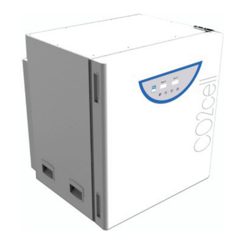
MMM Group VACUCELL 22 User manual

VACUCELL 22, 55, 111
Instructions for use
Vacuum cabinets - line Standard
VACUCELL-S_np_en_1105_mmm_V2.07_B2V
1iYRGNSRXåLWt
9DNXRYpVNĜtQČOLQLH.RPIRUW
9$&8&(//.BQSBF]BB9B%9

Congratulations on obtaining a new temperature cabinet, Temperaturesensitive,easy decomposable
or oxidative materials, can be dried very tenderly in VACUCELL, vacuun drying ovens, vhere is the
opportunity of extrusion of air by inert gas. Also complicated components with hardly accessible hollow
spaces are drying quick and affectivelly in VACUCELL ovens.
The units meet technical and legislative requirements and they are designed according to respective
EN standards. The units are made of high quality materials by using the latest technology. Each piece
undergoes a careful output control.
Provided you will follow the instructions mentioned here the unit becomes your reliable and powerful
partner.
Now these advantages will be available just for you. This unit will help to solve your everyday problems
and it will become powerful assistant for you. This unit is very easy to use, nevertheless, we recommend
you to read the Instructions for use carefully so that you could use all advantages of this unit and obtain
complete knowledge for its optimal use.

CONTENTS: 18. 5. 2011
1 GENERAL INFORMATION.................................................................................................................3
1.1 SCOPE OF VALIDITY.........................................................................................................................3
1.2 PURPOSE..........................................................................................................................................3
1.3 USE..............................................................................................................................................3
2 IMPORTANT INSTRUCTIONS...........................................................................................................3
2.1 UNPACKING, CHECKING,TRANSPORT AND HANDLING.................................................................................3
2.2 BEFORE PUTTING INTO OPERATION.......................................................................................................3
2.3 USEFUL SPACE................................................................................................................................4
2.4 WIRING AND OTHER CONDITIONS......................................................................................................4
3 DESCRIPTION OF THE UNIT............................................................................................................5
3.1 GENERAL VIEW.................................................................................................................................5
3.2
CONTROL PANEL IN THE DOOR OF THE BOX.............................................................................................5
3.3 CONTROL PANEL IN THE SUPERSTRUCTURE............................................................................................6
3.4 MAINS CONNECTION AND CONNECTORS.................................................................................................6
4 FUNCTION AND OPERATION..........................................................................................................6
4.1 SWITCHING ON.................................................................................................................................7
4.2 SWITCHING OFF...............................................................................................................................7
4.3 ADDITIONAL USER FUNCTIONS............................................................................................................7
4.4 SETTING THE REQUIRED VALUES OF TEMPERATURE, TIME-DELAYED SWITCHING-OFF, NUMBER OF CYCLES,
AND TIME-DELAYED SWITCHING-ON......................................................................................................8
4.5 LIST OF ERROR MESSAGES.................................................................................................................9
4.5.1 ERRORS OF THE CONTROL SYSTEM................................................................................................9
4.5.2 SAFETY SYSTEM ERRORS............................................................................................................9
4.5.3 NOT-DISPLAYED ERRORS..............................................................................................................9
4.6 PROTOCOL PRINTING......................................................................................................................10
4.6.1 INSTALLATION AND SETTING OF THE PRINTER...............................................................................10
4.6.2 PRINTING..........................................................................................................10
4.7 SAFETY SYSTEM............................................................................................................................10
4.7.1 CHANGE OF THE MAXIMUM AND MINIMUM VALUES...........................................................................11
4.7.2 DIAGRAM OF THE SAFETY SYSTEM FUNCTION................................................................................11
4.7.3 CHECKING THE SAFETY RELAY FUNCTION.....................................................................................11
4.7.4 CONTROL OF THE CORRECT FUNCTION OF THE CHECK CIRCUIT............................................................11
4.8 CREATION OF VACUUM IN THE CHAMBER.............................................................................................12
4.9 SEALING EXCHANGE AND DOOR SETTING.............................................................................................12
5 SPECIFICATIONS OF THE UNIT.....................................................................................................13
6 CLEANING.......................................................................................................................................14
7 MAINTENANCE.......................................................................................................................14
8 WARRANTY CONDITIONS AND SERVICE; GUARANTEED LIFETIME.......................................14
9 TRANSPORT AND STORAGE........................................................................................................14
10 METHOD OF LIQUIDATION OF THE PACKING AND OF THE DISCARDED UNIT.......................15

11 OPTIONS..........................................................................................................................................15
11.1 SUPPORTIVE SW FOR PC...............................................................................................................15
11.2.1 RECORDING SW - WARMCOMM - FOR PC UNDER WINDOWS........................................................15
11.2.2 RECORDING PRINTING SW - PRINTER ARCHIV - FOR PC UNDER WINDOWS.......................................15
11.2 BOX „VACUSTATION“.......................................................................................................................15
11.3 CHEMICALLY RESISTANT VACUUM PUMP..............................................................................................16
11.4 SEPARATOR AND EMISSION CONDENSER.............................................................................................16
11.5 INDEPENDENT PT100 SENSOR...........................................................................................................16
11.6 INDEPENDENT PRESSURE SENSOR......................................................................................................16
APPENDICES:
EC - DECLARATION OF CONFORMITY

1 GENERAL
INFORMATION
1.1 SCOPE OF VALIDITY
These instructions apply to the device series
VUS-B2V and VUS-B2V-M.
1.2 PURPOSE
VACUCELL (VU) is an electrically heated and
evacuated chamber which may be used after
evacuation to heat the objects located in it.
Evacuated objects are placed on the shelves in
the chamber. The device works at temperature
up to 200 °C.
The temperature course is controlled by a
modern microprocessor (Fuzzy-logic) with
digital display and PT 100 temperature
sensor. This system ensures high precision
of temperature regulation and reliability of
the tempering process.The unit has been
designed, produced and tested according to the
appropriate European standards. It complies
with the legislative requirements of LVD and
EMC directives – see the attached declaration of
conformity. It is made of high-quality materials,
using the latest technology. Each piece goes
through a careful output control.
1.3 USE
VACUCELL is designed to perform:
- vacuum drying of easy oxidable matters with
possible displacement of oxygen by inert gas
- accelerated drying of form-simple and
complicated parts
- drying of samples up to constant weight at
adjustable temperature and selectable time
mode.
The unit may be used primarily in the following
branches:
- biology
- cosmetics
- pharmaceutics
- food industry
- chemistry
- electric technology
- plastics processing
- engineering
The unit is designed to be used and handled
by the persons familiar with dealing with the
laboratory equipment and apparatuses.
2 IMPORTANT
INSTRUCTIONS
2.1 UNPACKING, CHECKING,
TRANSPORT AND HANDLING
After unpacking please check that the unit and
the accessories are complete and undamaged).
Possible damage must be immediately reported
to the transporter. When handling - lifting the box,
etc - the box must not be lifted using the hand
rail or the door! Lift the box using the four hooks
that you push into the openings in the side of
longitudinal legs of the box.
Standard delivery consists of the cabinet and
two shelves.
(order No.: V459046 - volume 22
V 459047 – volume 55
V 459048 – volume 111),
silicon hose 8 x 18 for connection chamber/
vacuum source (order No. 0662132)
2.2 BEFORE PUTTING INTO OPERATION
Ɣ Before beginning the work with the unit
please read the Instructions for use
carefully!
Ɣ Install the unit by plugging the power cord
WRWKHPDLQV+RZHYHUPDNHVXUHDW¿UVW
that the mains parameters correspond to
WKHYDOXHVVSHFL¿HGRQWKHXQLWW\SHODEHO
and to the data shown in Chapter 5.1 -
Electric Connection!
The unit is designed to work indoor within
the ambient temperatures range of from
5 °C up to 40 °C, at maximum relative
humidity of 80 %, up to the maximum
altitude of 3 000 m.
Minimum distance of the unit from the rear
and side walls is 100 mm.
Ɣ 'RQRWSODFHLQÀDPPDEOHRUH[SORVLYH
matters into the unit! In case of
temperatures above 100 °C a yellowed
stain of the inner chamber walls can occur.
This stain is neither the material nor the
XQLW¶VGHIHFW$IWHUWKH¿UVWVZLWFKLQJRQ
the heating bodies start to be burnt, which
results in a characteristic smell; this smell
disappears after several operating cycles.
Place the material to be warmed-up on the
shelves only, not on the bottom of the unit.
Instructions for use
VACUCELL-S_np_en_1105_mmm_V2.07_B2V 3

1RLQÀDPPDEOHH[SORVLYHRUWR[LF
materials can be inserted to the unit! The
same concerns also materials material
giving off such a stuff!
The unit is not designed to warm-up liquids
and it contains no liquids.
In case of any manipulation with the unit,
other than its normal use, or if you do not
use it for a longer period, disconnect it from
electric mains by pulling the supply cord
from the socket (position 2 –upper part
panel)! When depressing the key ON/OFF
the unit is set only in the stand-by mode,
put it is not disconnected from electric
mains!
Any assembly or disassembly may be
done only when disconnected from the
mains! After switching the unit off with
WKHNH\NH\¿JWKHXQLWFRPHV
only to a stand-by mode, however, it is
not disconnected from the mains!
Maximum permissible load: see chapter
6SHFL¿FDWLRQVRIWKHXQLW
Goods are only to be put on trays into
ovens, never directly on the bottom of the
oven!
Do not put any object on the outer surfaces
of the ovens.
Aparatus may not be used in the
atmosphere with a possible danger of
ÀDPPDEOHRUH[SORVLYHDQHVWKHWLFV
No dangerous goods are permitted. Ovens
may not be used for heating of liquids.
ƔProtection of the thermal cabinet, its
surrounding and the treated material
against inadmissible temperature rise is
ensured by a protection thermostat.
The maximum permissible temperature
has been set to the maximum value in the
factory
&DUU\LQJFDSDFLW\RIWKHÀRRUGXULQJ
installation of the device must correspond
to the weight of the unit itself taking
the weight of the maximum charge into
consideration (see chapter 5 - Parameters
of the unit).
If the device is used in another that
VSHFL¿HGZD\WKHSURWHFWLRQSURYLGHGE\
the device could be impaired.
2.3 USEFUL SPACE
Useful space is illustrated in Fig.1, where X(H) =
10% of the interior chamber depth, X(Š) = 10% of
the interior chamber width, X(V)1is the distance
od the lowest shelve from the bottom of interior
chamber, X(V)2is the distance of the top shelve
from the top of the interior chamber. Within
the space limited by said surfaces (according
to the standard DIN 12 880 - illustrated by
thick lines, thinner lines illustrate the interior
walls of the chamber) temperature deviations
stated in chapter6SHFL¿FDWLRQVRIWKHXQLW
are maintained). It means, that over the last
upper tray there are the limits from in chapter
6SHFL¿FDWLRQVRIWKHXQLW not obligatory.
Fig. 1
2.4 WIRING AND OTHER CONDITIONS
Basic data for connection:
Mains
connection:
[9+]
1x110-125V/50(60)Hz;
(standard types are marked with bold face)
0DLQVYROWDJHÀXFWXDWLRQ ±10 %
Protection against dangerous contact - class: I
External circuits isolation:
– double isolation
Type of unit plug:
– as a standard CEE-7/VII, IEC-83/CH,
16 A/250 V (or another according to the type)
Socket protection:
– 10 A
Protection according to EN 60529: IP 20
Overvoltage category according to
,(&(1
– II in case of pollution degree 2
Fuses on the rear wall of the upper piece: T 10 A
Ambient conditions:
– ambient temperature: +5 °C to +40 °C
– max.relative humidity: 80% at 31 °C
– maximal altitude: 3000 m
Instructions for use
4VACUCELL-S_np_en_1105_mmm_V2.07_B2V

Instructions for use
VACUCELL-S_np_en_1105_mmm_V2.07_B2V 5
3.2 CONTROL PANEL IN THE DOOR OF
THE BOX
Fig. 3
1 - Display
2 - Decimal point - lights (the unit is connected
to the mains - stand-by condition)
3 - Preselected programs indicator lamps-
lights: program is active
- blinks: program will be active in 5 sec.
5 - Heating indicator lamp - lights:condition of
temperature regulator - heating active
6 - Switching-on indicator lamp - lights after
switching the unit on by the depression of
ON/OFF
7 -
6DIHW\V\VWHPLQGLFDWRULVÀDVKLQJ7KH
temperature exceeded the chosen limit set
by the protective thermostat – the heating
is switched off (see more in Chapter Safety
System Functions and Setting)
8 - Setting-up mode activation button
9 - Setting the value downwards
10 - Setting the value upwards
11 - Switch (ON – switched on, OFF - stand by
condition)
12 - Adjustable protecting thermostat - outer
rotary ring
13 - Button (RESET) to set the protecting
thermostat in operation again
14 - Indicator lamp: blinks - setting-up mode,
lights - active part of the program is time-
delayed switching-on
15 - Indicator lamp: blinks - setting-up mode,
lights - active part of the program is heating
upto set temperature
16 - Indicator lamp: blinks - setting-up mode,
lights - active part of the program is time-
delayed switching-off
17 - Indicator lamp: blinks - setting-up mode,
lights - decrease of temperature after
switching-off
18 - Indicator lamp: blinks - seting-up mode,
OLJKWVDFWLYHSDUWRIWKHSURJUDPLVLQ¿QLWH
stay on set-up temperature
Indicator lamps 14-18 blink - mode of number of
cycles setting.
3 DESCRIPTION OF THE
UNIT
3.1 GENERAL VIEW
Fig. 2
1 - Panel of the regulator
2 - Control panel
3 - Control panel cover
4 - Panel of the superstructure
5 - PT 100 temperature sensor and safety
Thermostatsensor
6 - Heating bodies
7 - Power part
8 - Power supply cord
9 - Built-in socket for the vacuum pump
10 - 9DFXXP¿WWLQJV
11 - Inlet to connect the vacuum pump
12 - Heat resisting glass of the door
13 - Measuring feedthrough
14 - RS-232C connector
15 - Supply of inert gas to the needle valve
16 - Ball valve.

6VACUCELL-S_np_en_1105_mmm_V2.07_B2V
Instructions for use
3.3 CONTROL PANEL IN THE
SUPERSTRUCTURE
Fig. 4
1 - Mains main switch indicator
2 - Mains main switch
3 - Ball valve connecting the chamber and the
vacuum pump, in position ON is valve open
4 - Needle valve to add inert gas or air
5 - Vacuometer
6 - Indicator of the mains switch of built-in
socket in the superstructure
7 - Mains switch of the built-in socket in the
superstructure - for the vacuum pump.
3.4 MAINS CONNECTION AND
CONNECTOR
The mains connecting cord passes through
the bush in the left part of the upper piece to
the power board located in the upper piece.
In the right part of the upper piece there is
a RS232 C connector and a built-in socket for
the vacuum pump. Both of them are accessible
DIWHUOLIWLQJWKHFRYHURII±VHHWKH¿JXUHEHORZ
In the right rear part of the upper piece there is
an opening through which the pump hoses and
hoses with inert gas are connected to the unit.
3 - mains socket (for the vacuum pump)
4 - RS-232C connector to connect the printer
Fig. 6: Interface for protocol printer:
9 pin Canon connector on the case
Pin Signal
2 RX
3 TX
5 GND
6 DTR
25 pin Canon connector in the printer
Pin Signal
2 TXD
3 RXD
7 GND
20 DTR
Ovens connected by RS-232C connector
must meet the regulations and be approved
by the testing laboratory. The unit is designed
to connect the CITIZEN printer type iDP 3110-
24 RF-A vhich may be ordered to be delivered
to the unit.
Interface parameters:
Baud: 9600
Stopbit: 1
Parity: none
Databit: 8
4 FUNCTION AND
OPERATION
The unit can be set to several modes according
to the required function; i.e. its cycle can be
PRGL¿HGDVGHVFULEHGEHORZLQWKHWH[W
Figure 7 shows the overall course of one cycle
and its distribution to the individual phases.
t (x)
t (°C)
0a b t (min)c
Fig.7
Phase Function
0 Time-delayed switching-on
a Temperature rise
b Time-delayed switching-off
c Temperature decrease after switching-off

The functions of the respective indicator lights
are described in chapter 3 - Description of the
Unit, and 3.3 - Control Panel.
4.1 SWITCHING ON
1. Green indicator of the mains switch and
green indicator in the right lower corner of
the display (condition [stand by]) shine after
connection to the mains and after switching
on the mains switch on the panel of the
superstructure.
2. Press the button ON/OFF.The indicator above
the button, the indicator of one of the preset
programmes, and the indicator of the initial
active phase of the programme will switch
on. If the preset temperature is higher than
that in the chamber, the heating indicator
is switched on as well - either permanently
or intermittently (depending on whether the
heating regulator is switched on or off).
3. The display shows the real data related to the
active phase of the programme.
4. Mains switch to the left of the panel in the
superstructure serves to switch on the mains
socket of the pump (built-in in the shaft of the
superstructure).
4.1 SWITCHING OFF
Press the button ON/OFF. The display turns off;
the green indicator only in the right bottom part
(stand by) is on.
The unit is disconnected from the mains by
switching the power switch off. If the unit is to
be repaired or shut down for a longer period,
pull the plug of the mains cable from the socket
– see also chapter 2.2 - Before Putting into
Operation.
4.3 ADDITIONAL USER FUNCTIONS
Enter the user functions by concurrent pressing
the buttons X/Wź
8VLQJWKHEXWWRQVźŸ\RXFDQEURZVHWKHXVHU
functions and change the parameters of the
individual functions. The changed values, except
for changes of functions U6, U7, and U8, will
automatically be stored in the memory.The given
function parameters setting is entered and exited
by pressing X/W. Exit the user functions mode by
pressing ON/OFF
U1 – printer’s printing period setting (Per.P) from
1 to 255 min, or the print period switch-off
(“OFF”) by means of buttons źŸ.
VACUCELL-S_np_en_1105_mmm_V2.07_B2V 7
Instructions for use
U2 – (CYcl) On or OFF – cycles permit or
prohibition are set by means of źŸ
(for all pre-sets at once); a cycle means a
multiple programme repetition with a pre-
set delayed switching off and on.
U3 – Prn or PC – data transfer via interface
RS 232 either onto the printer (Prn) or, in
case of using the program WarmComm,
onto the computer (PC); set the sign Prn or
3&E\PHDQVRIźŸ.
U4 – Not used.
U5 – Permission (Snd) or prohibition (OFF)
of acoustic signalling after exposure
termination (after the last cycle exposure
in case of recycling). The acoustic signal
consists of three subsequent tones (there
is a short high beep between the eventual
individual cycles). The original setting
permits the acoustic signalling.
U6 – Safety system functioning as a protective
thermostat
User safety upper temperature limit
– setting of the maximum user-permitted
exposure temperature (SFt.H). Change this
value by means of źŸDQGFRQ¿UPE\ON/
OFF pressing. When setting this maximum
value, the real temperature course, namely
its potential overshoot during temperature
rising, must be taken into account. If the
pre-set maximum permitted temperature is
lower than the required exposure temperature,
the display shows the warning “SEt tEMP
CroSSEd SAFEtY USEr LiMit” , because the
safety system would otherwise be activated
during the cycle. The resolution and range of
the setting correspond to the resolution and
range of the required temperature. The highest
temperature has been pre-set as default.
U8 – Safety system – setting of the maximum
RQVHWSKDVHGXUDWLRQ63WI$IWHUźŸ
pressing, the actual maximum onset
phase duration is displayed. It can then
be changed by 1-hour steps within the
range from 1 to 24 hours, or the time
watching can be switched off, which is
then displayed in form of “OFF³&RQ¿UP
by ON/OFF pressing. Default setting: Time
watching is switched off.
U9±6HOHFWLRQRIWKHÀH[LEOHVHQVRUGLVSOD\<HV1R
U10 – Selection of the pressure sensor display
(Yes/No).
U14 –Alarm – setting of the permitted lower
deviation from the required exposure
temperature (dlt.L). Set the deviation by
means of in the range from -0.1 to

8VACUCELL-S_np_en_1105_mmm_V2.07_B2V
Instructions for use
cycles – see Chapter 4.3). All indicators will
ÀDVKGXULQJWKHVHWWLQJ7KLVIXQFWLRQFDQ
RQO\EHXVHGLQVHWWLQJRIDVSHFL¿FYDOXHRI
the time-delayed switching-off. Select the
possibility of the cycles setting by means of
the user supporting function.
5. By pressing the button X/W, enter the
phase of the time-delayed switching-on.
8VLQJWKHEXWWRQVźŸVHWWKHUHTXLUHG
value in minutes from 0 to 99 hours 59 min.
7KHLQGLFDWRU)LJÀDVKHV
6. Double pressing of ON/OFF starts the
programme (the programme start is
signalled by an acoustic signal).
In the phase of the time-delayed switching,
the real temperature and time countdown
ÀDVKRQWKHGLVSOD\$IWHUUHDFKLQJWKH
zero time, the heating switches on and the
display shows the real temperature in the
chamber.
After the required temperature is achieved
a) And the time-delayed switching-off is
preset: The temperature in the chamber
ZLWKWKHWLPHFRXQWGRZQVWDUWÀDVKLQJRQ
the display;
b) And switching-off is unlimited: The
temperature in the chamber with the
ULVLQJWLPHÀDVKRQWKHGLVSOD\
Continuously shining indicators inform about
the actually active programme segment.
7. You can control the individual values setting
during the programme run – after pressing
X/W, the display shows the required value.
7KHLQGLFDWRUVÀDVK%HIRUHVHFRQG
passes, press X/W again to enter the
subsequent phase. In this way, you can
check gradually all the settings. If you do
not use any control element, the original
programme will continue.
8. The already preset values can be changed
in a similar way during the programme run, if:
a) You wait for about 5 seconds after the
last value – time-delayed switching-
on – setting. The programme with the
changed values then continues from the
point of interruption;
b) You start the programme after the value
setting by double pressing the button ON/
OFF. The programme with the new values
will start running from the beginning.
-99.9 °C, or the function can be switched
off, which is displayed as “OFF”. The
alarm function has been switched off as a
default.
U15 – Alarm – setting of the permitted upper
deviation from the required exposure
temperature (dlt.H). Set the deviation by
means of in the range from +0.1 to 99.9
°C, or the function can be switched off,
which is displayed as “OFF”. The alarm
function has been switched off as a
default.
Exit any user function setting by X/W pressing.
Exit any user function selection by ON/OFF
pressing.
4.4 SETTING THE REQUIRED VALUES
OF TEMPERATURE, TIME-DELAYED
SWITCHING-OFF, NUMBER OF
CYCLES, AND TIME-DELAYED
SWITCHING-ON
1. Set the preselection of the programme 1,
RUE\PHDQVRIźRUŸ$IWHUSUHVVLQJ
WKHEXWWRQźRUŸWKHVXEVHTXHQW
SURJUDPPHLQGLFDWRUVWDUWVÀDVKLQJ7KLV
programme will become activated after
about 7 seconds if no other button is
pressed during that time. Transfer by means
RIźRUŸZLOOVWRSWKHUXQQLQJF\FOHDQG
start a new cycle with the pre-selected
parameters.The setting cycle begins with the
required temperature setting.
2. Press the button X/W. The indicators 15
DQG)LJVWDUWÀDVKLQJ8VLQJWKH
EXWWRQVźŸVHWWKHUHTXLUHGWHPSHUDWXUH
[°C] on the display.The least adjustable and
displayable temperature interval is 1 oC.´
7KHVHJPHQWVLQGLFDWRUVVWLOOÀDVK
3. Enter the phase of the time-delayed
switching-off by pressing X/W. Using
WKHEXWWRQVźŸVHWWKHUHTXLUHGYDOXHLQ
hours and minutes (from 0 to 99 h 59 min)
on the display. The indicators 16 and 17
)LJZLOOÀDVK7KHV\PERO³³PHDQV
a time unlimited exposure. After 99 hours:
59 min, time is displayed in hours only and
after 999 hours, it is displayed by fsymbol
LQ¿QLW\:KHQSULQWLQJWKHUHFRUGLQWKH
printer, time is shown in the hhh:mm format;
DIWHUH[FHHGLQJWKHWH[WÄLQ¿QL³LV
printed.
4. By pressing the button X/W, enter the
phase of the number of cycles setting and
set the number of cycles from 1 to 255 by
PHDQVRIźŸPRUHLQIRUPDWLRQDERXWWKH

VACUCELL-S_np_en_1105_mmm_V2.07_B2V 9
Instructions for use
4.5 LIST OF ERROR MESSAGES
When there is an error announced on the dis-
play, you can use the buttons źand Ÿswitch to
display the textual error description and/or other
error-related data recorded in the moment of the
error occurrence. Press X/W to exit this display.
Cancel the error message (by X/W pressing and
holding for about 2 s) and then follow the
instructions. If you do not succeed in the error
removing, contact the service technician.
Er 11 – Wrong temperature sensor of the safety
system
Contact the service centre.
Er13 – The temperature exceeds the user upper
limit watched by the safety system.
Check the limit setting in the user mode U6:
The limit may not be lower than the required
temperature, taking also account of overshoot or
ÀXFWXDWLRQ
After you change the value, check by a repeated
entry in the U6 mode whether the pre-set value
has been saved. If not, check the correct setting
procedure in the instructions for use.
Check also whether the device has not been
overheated without the device fault, e.g. by the
load ignition.
Er15 – The device threshold temperature watched
by the safety system has been exceeded.
Check whether the device has not been
overheated without the device fault, e.g. by the
load ignition.
Er17 – The maximum phase time was exceeded
If there is any error during the temperature rise,
compare the rise duration with the setting in the
user mode 8 and/or assess the reasons for the
long rise duration, or increase the maximum
controlled period in mode U8.
Er23 – the temperature measured by the control
system differs from the temperature measured by
the safety system.
Check whether the error was not caused by
strong temperature changes, e.g. by the door
opening and air blowing.
Er24 - The safety relay did not pass the test
Contact the service centre.
Er 50 and Er 51 – Wrong regulatory sensor
Contact the service centre.
(UDQG(U±(UURUVRIÀH[LEOHVHQVRUV
&KHFNWKHLQWHJULW\RIWKHÀH[LEOHVHQVRU
SEt tEMP CroSSEd SAFEtY USEr LIMIt.
Warning message informing only that the pre-
set temperature is either lower or higher, but
too close (up to 3 °C) to the user safety upper
temperature checked by the safety system (U6),
which probably will cause the safety system
activation. Cancel the message by X/W pressing
and change one of the two given values.
Hi ALARM
Lo ALARM
Alarm activation announcement. See the chapter
ALARM FUNCTION
Other error messages
Disconnect the device from the power supply and
then reconnect it.
If the error repeats, contact the service centre.
Er 54 and Er 55 – Errors of pressure sensors
Check the pressure sensor integrity.
Contact the service centre.
4.5.3 NOT-DISPLAYED ERRORS
Red LED with the safety thermostat symbol is
lighting, the control unit does not react. The
safety system has disconnected the safety
relay; there is no current supplied to the
heaters.
Disconnect the device from the power supply and
re-connect it.
The device does not display any information
GDUNGLVSOD\ Check whether the device is
connected to the power mains. If yes, try to
disconnect and re-connect it.
The device does not react to any button.
Disconnect the device from the power supply and
re-connect it.
The printer either does not print anything,
or prints some nonsense. Check whether the
device is switched to data sending to the printer
(U3); check the print period (U1). Check whether
the printer is connected to the power supply and
switched to the transfer speed 9600 Bd.
The temperature overshoots the required
temperature markedly during the exposure
cycle and reaches it only after some time.
Check proper closing of the unit door.
The temperature exceeds markedly the
required value during the exposure cycle and
the device continues to be overheated.
Switch off the device.
The temperature reaches the required
temperature during the exposure cycle only
after a too long time. Check proper closing of
the unit door. Check whether the power mains
KDYHUHTXLUHGYDOXHVVSHFL¿HGLQWKH,QVWUXFWLRQV
for Use, chapter Power Mains Connection.

10 VACUCELL-S_np_en_1105_mmm_V2.07_B2V
Instructions for use
printing. The interval is shown in the record
heading.
The printer interval can be set on the display
in the range from
tmin = 1 min to tmax = 255 min
(i.e. 4 hours 15 min) in 1-minute increments.
4.6.2 PRINTING
1. The printer prints out the heading showing the
device type, programme number, number of
cycles, pre-set temperature, time of the start
delay, and the required time interval.
2. Then the printer prints out the procedural
data and titles of the procedural data columns
(physical unit inclusive).
3. Below that, the values of the following
procedural data are printed out:
- Actual temperature in the chamber;
- Time from the programme start.
4. Other printed data:
- Start of individual phases;
- Change of any required value;
&KDQJHRIDXVHUIXQFWLRQLQÀXHQFLQJ
the cycle procedure (U1, U3, U4, U6, U8) m,
including
the new value printing;
- Alarms activation/deactivation, including
the description;
- For IC,ICV: Activation or deactivation
of the safety system warning, including
the description;
- Error state activation, including the
description.
5. In case of power failure and subsequent
power recovery, the printer prints out “-->
Power recovery!” Counting of the printing time
intervals starts from the moment of power
recovery. A new heading is printed out after
switching the device off and on by means of
ON/OFF.
If there is a power failure of the printer only, or
if the printer is switched off, the printer shows
no message after the power recovery or the
printer switch-on.
4.7 SAFETY SYSTEM FUNCTION AND
SETTING
The safety system watches the exposure process
controlled by the control circuit. It also performs
the function of a safety thermostat and serves to
protect the temperature box, its surroundings and
the processed material against an inadmissible
excess of the set temperature (it will e.g. prevent
The temperature never reaches the required
value during the exposure cycle. Check whether
WKHSRZHUPDLQVKDYHUHTXLUHGYDOXHVVSHFL¿HG
in the Instructions for Use, chapter Power Mains
Connection.
4.6 PROTOCOL PRINTING
DPT 6333 printer is recommended for the record
printing on the printer. Other printers may also be
used, e.g. CITIZEN, model iDP
3110-24 RF-A. Printing to a PC application
(Printer Archiv) is allowed as well.
4.6.1 INSTALLATION AND SETTING OF THE
PRINTER
DPT-6333-V24 does not require any microswitch
setting by the user.
Setting the DIP microswitches of the printer
CITIZEN iDP 3110:
all four pins are in the lower position OFF.
Setting the DIP microswitches of the printer
CITIZEN CBM 910:
OFF / ON / OFF / ON / OFF / ON / ON / OFF
(from the left to the right).
CBM 910II: OFF / ON / OFF / OFF / OFF / OFF
/ ON / OFF.
After the setting is changed, the printer must be
switched off and on either by the switch or by
disconnection from the power supply.
(A different type of the printer must be adjusted
with the help of the printer´s manual and the data
on the interface RS232 shown on the case.)
Connect the printer to the device by means of a
cable with serial connector (RS-232C). Connect
one end of the cable to the printer socket (see
Fig. 4) and the other one to the connector in the
rear part of the printer. Connect the printer to the
electric power mains by means of an adapter.
Some types require the switch on the right side
of the printer to be switched on. The indicators
POWER and SEL light up. The printer is in the
on-line mode. Paper is fed by pressing the LF
button (in the on-line mode only, i.e. after the SEL
button pressing – the SEL indicator turns off. To
renew the on-line mode, the SEL button must
be pressed – the SEL indicator lights up). The
printer can print in the on-line mode only!
Follow the chapter User Support Functions to set
the type of data from the COM output connector
(user mode U3) and the required print interval
(user mode U1).
By the printer interval setting you can determine
the time intervals of actual chamber temperature

the damaging or destruction of material samples
in case of the temperature regulator damage, or
unintended setting of a higher temperature than
that tolerated by the sample in the unit chamber).
Supervision is performed both under the normal
operation and in a Stand By.
The safety system measures the temperature
independently at the same place like the
regulatory sensor and counts the time
independently. If the set maximum temperature
and period of time are exceeded, the safety
relay switches off the heating, indicates the error
VWDWHE\LWVLQGLFDWRUÀDVKLQJUHGDQGSDVVHV
the information about the error to the controlling
unit which then passes to the error regimen and
indicates the error.
To cancel the error by the user, hold X/W. The
controlling unit cancels the error state in the
safety system circuit. The device passes to a
break state in which parameters can be reset, or
you can let the chamber cool. The device is put
into operation by pressing ON/OFF.
4.7.1 CHANGE OF THE MAXIMUM VALUES
It is carried out in the user settings U6 and U8
– see the diagram of the safety system function
and the user settings description. Minimum
difference from the regulated temperature set
should be ± 5 °C.
4.7.2 DIAGRAM OF THE SAFETY SYSTEM
FUNCTION
T limiting – threshold temperature is the
maximum operation temperature permitted by the
manufacturer in all phases and watched by the
safety system. Its value depends on the device
type and cannot be changed.
T User High – safety user upper temperature
limit is the maximum temperature permitted by
the manufacturer for the phase of temperature
rise, exposure and cooling, pre-set in U6 and
watched by the safety system.
T delay – Maximum permitted temperature of the
time-delayed switching-on phase. It sets itself at
the beginning of the delay phase to the value of
the actual temperature increased by 30 °C.
VACUCELL-S_np_en_1105_mmm_V2.07_B2V 11
7¿QDO- maximum permitted temperature after
termination of cooling. It reaches the T exp max
temperature or 55 °C, whichever is lower.
D delay - time of the delayed switching may vary
from the set time for ± 2 min.
D rise - max. rise time according (Safety Time) to
the setting in the user mode U8.
D exposition - exposition time may vary from the
set time for +3 min / - 0 min.
D cooling - max. cooling time is set to 24 hours.
7OLPLWLQJWHPSHUDWXUHVHWWLQJKDVEHHQ¿[HG
to +230 °C. (Setting of the values before the
product dispatch – maximum permitted exposure
temperature is +220 °C; minimum permitted
exposure temperature is +10 °C; maximum rise
time is 6 hours.)
4.7.3
CHECKING THE SAFETY RELAY
FUNCTION
The test is performed automatically in the
phase of the temperature rise, without the cycle
LQÀXHQFLQJDQGDIWHUWKHSHULRGEHWZHHQWHVWV
elapsing (3,000 hours). The said time is counted
in the exposure phase. After the device is
connected to the power mains, the safety relay
state is monitored as well. If the test result is not
good, Err 24 is announced.
4.7.4 CONTROL OF THE CORRECT
FUNCTION OF THE CHECK CIRCUIT
This control shall be carried out after
stabilization of the required temperature (10
minutes at least).When changing the permitted
temperatures in U6 and U7, do not forget to
record each temperature change in the safety
system by pressing the ON/OFF button before
leaving the user mode.
Control of temperature exceeding:
x Activate the user service U6.
x Set the maximum permitted temperature to a
value 5 °C over the required temperature. The
safety circuit must not react.
x Set the maximum permitted temperature to a
value 5 °C below the required temperature.
The safety circuit must react. LED of the
safety thermostat is switched on and Er13
error is displayed.
Low temperature control:
x Activate the user service U7.
x Set the minimum permitted temperature to a
value 5 °C below the required temperature.
The safety circuit must not react.
x Set the minimum permitted temperature to a
Instructions for use
7¿QDOPD[DOORZHGWHPSHUDWXUHDIWHU¿QLVKLQJ
.ÖVODKPOUÅIT¤,3)nLINIE3TANDARD"VSTRANA6?44,3)?3?C?NP 'LDJUDPIXQNFHNRQWUROQtKRREYRGX
Ĝ
ČKXH[SR]LFHLFKODGQXWtGOHQDVWDYHQtYXåLYDWHOVNpPPyGX
7H[SPLQ PLQLPiOQtGRYROHQiWHSORWDIi]HH[SR]LFHGOHQDVWDYHQtYXåLYDWHOVNpPPyGX
7]SRå PD[GRYROHQiWHSORWDIi]H]SRåGČQpKR]DSQXWt1DVWDYtVHVDPDQDGOHVNXWHþQpWHSORW\&
7NRQHþQi PD[GRYROHQiWHSORWDSRVNRQþHQtFKODGQXWt-HVWHMQiV7]SRå
']SRå GRED]SRåGČQpKR]DSQXWtVHPĤåHOLãLWRGQDVWDYHQpRPLQ
Č ČKXGOHQDVWDYHQtYXåLYDWHOVNpPPyGX
ĤåHOLãLWRGQDVWDYHQpRPLQPLQ
'FKODGQXWtPD[GREDFKODGQXWtMHQDVWDYHQDQDKRGLQ
2GHþtWiQtþDVXPH]LWHVW\EH]SHþQRVWQtKRUHOp
þtWDGOR VH VQLåXMH SĜ þHWt NDåGp QRYp KRGLQ\ H[SR]LFH -HKR VWDY MH ]REUD]HQ
YXåLYDWHOVNpP PyGX 8 3ĜL GRVDåHQt VWDYX MH Y\åDGRYiQ SĜ
þQRVWQtKR UHOp MLQDN QHQt H[SR]LFH XPRåQČQD 'REUê YêVOHGHN WHVWX WRWR SRþ
]QRYXQDVWDYtQDYêFKR]tVWDYK
7HVWEH]SHþQRVWQtKRUHOp
Č Č þDVX PH]L WHVW\ 3RNXG WHVW SUREtKi
Y\SLVXMH VH QD GLVSOHML NURPČ VNXWHþQp WHSORW\ UHJXODþ Ĝ Č þ
3RNXGVH]REUD]XMHÄ6$)(7<7(67±6(77(03(5$785(83³YHVNĜ ČY\VRNi
WHSORWD±QXWQRQHFKDWY\FKODGLW7\WRQiSLV\VH]REUD]XMtLYHIi]L]SRåGČQpKR]DSQXWt
7HVW MH DOH WDNp PRåQp VL Y\åiGDW YXåLYDWHOVNpP PyGX 8 3RNXG WHVW SUREČ Ĝ
Ĥ 3RNXG WHVW QHSUREČ Ĝ
Y\KOiãHQDFK\ED(UU
Tmezní
TåiGDQi
Texp max
Texp min
Teplota
ýas
7]SRå TNRQHþná
D ]SRå D nábČhu Dexpozice Dchladnutí
T VNXWHþná
2GUiåN\D
þtVORYiQt
T limit
T exp max
T exp min
7¿QDO
D cooling
T delay
Time
D rise
Temperature
D exposition
D delay
T desired
T actual
WKHUHJXODWLQJDQGSRVVLEO\WKHÀH[LEOHVHQVRU
UserHigh

12 VACUCELL-S_np_en_1105_mmm_V2.07_B2V
Instructions for use
1
2
3
4
value 5 °C over the required temperature.
The safety circuit must react. LED of the
safety thermostat is switched on and Er12
error is displayed.
4.8 CREATION OF VACUUM IN THE
CHAMBER
Push the hose from the vacuum pump onto
the end of the vacuum piping of the unit (Fig.2,
position 11) which is accessible through the side
cut-out in the superstructure. Connect the mains
cord of the vacuum pump into the socket in the
shaft of the superstructure and switch the pump
on. Set the ball valve on the front panel of the
superstructure into the position VAC ON. Value
of vacuum begins to rise on the vacuometer in
the front panel after several tens of seconds
(the needle valve and the door must be properly
closed).
4.9 SEALING EXCHANGE AND DOOR
SETTING
Take the whole sealing off, begin in the middle
bottom part. Fix the new sealing on the edge of
the chamber, begin in the middle bottom part.
Slam the sealing between the chamber and the
outer cover. To check up the tighteness place
a sheet of paper between the door and the
chamber when closing the door. Pull it out slowly,
you should feel a stronger resistance.
The door is adjustable at four points:
Pins of the lock 3, 4: on the left front part of the
jacket – at the top and at the bottom: these pins
can be loosened by means of the lock nut and
they can be adjusted forwards/backwards by
means of the thread.
Door hinge, lower 1: by loosening the screw
M8 at the front on the right side of the foot it is
possible to adjust the door forwards/backwards in
the horizontal direction.
Door hinge, upper 2: after removing the cover
of the extension part the screws M8 in the front
right corner become accessible. After loosening
these screws the position of the door can be
adjusted.
Adjust the door so that when closed the rubber
VHDOLQJRIWKHFKDPEHUZRXOG¿WWRWKHVKHHWRI
WKHÀRDWLQJGRRUDORQJWKHZKROHSHULPHWHU7R
check it up place a sheet of paper between the
VHDOLQJDQGWKHPHWDOVKHHWRIWKHÀRDWLQJGRRU
before it is closed, it is possible to take the paper
out against a small resistance.

5 SPECIFICATIONS OF THE UNIT
VACUCELL (VU)
Te c h n i c a l d a t a
Interior of stainless steel
material
DIN 1.4571(AISI316TI)
volume cca ltrs 22 55 111
width cca mm 340 400 540
depths cca mm 260 320 410
height cca mm 300 430 480
Shelves Shelves wiring
Standard equipment number max.
Pieces suppl 5
28
29
2
Shelves distance height mm 40 40 40
Usefull dim.of shelf width × depths mm 280x236 340x296 480x380
Max.permissible load of the
shelves one shelf
totally per unit kg
kg 20
35 25
45 25
65
External dimensions
(including door and handle) width
depths
height
cca mm
cca mm
cca mm
560
490
700
620
550
830
760
640
880
Package dimensions
(three layers carton) width
depths
height (incl.palette)
cca mm
cca mm
cca mm
740
615
915
830
635
1010
830
730
1070
Weight nett
brutt cca kg
cca kg 65
76 98
110,5 130
144,5
Electric parameters
– mains 50/60 Hz
max. input **)
input in stand by mode
current
For the nominal voltage***)
current
For the nominal voltage***)
kW
W
A
V
A
V
0,8
5
3,5
230
7
115
1,2
5
5,2
230
10,5
115
1,8
5
7,8
230
15,7
115
Temperature data
Working temp (regulation start) from 5 °C over ambient
temp to °C 200 200 200
Temp. deviations acc.to
DIN 12 880 Teil 2 from working
temp -Al shelvs pressure 5 – 10
mbar) ++)
at 100 °C accuracy
at 200 °C in space
to (±) °C
to (±) °C
2
<5
0,4
2
<6
0,4
3
<7
0,4
Temp. deviations acc.to
DIN 12 880 Teil 2 from working
temp-ss shelvs pressure 5 – 10
mbar) ++)í
at 100 °C accuracy
at 200 °C in space
to (±) °C
to (±) °C
10
8
0,5
10
23
1,0
11
1,0
Time of rise onto 98 %
voltage 230 V – (Al shelvs
pressure 5-10 mbar)
onto temp. 100 °C
onto temp. 200 °C min
min 60
80 65
85 110
130
Time of rise onto 98 %
voltage 230 V - (ssteel shelvs,
press 5-10 mbar)
onto temp. 100 °C
onto temp. 200 °C min
min 130
170 140
180 170
220
Heat radiation at 100 °C
at 200 °C W
W150
130 260
520 370
750
Vacuum connection vacuum connection
measuring feedthrough
needle valve for inert gas
or air
chamber untightness
DN mm
DN mm
Ø mm
mbar.l.s-1
16
40
8
İ5.10-3
16
40
8
İ5.10-3
16
40
8
İ5.10-3
1RWH$OOWHFKQLFDOGDWDDUHUHODWHGWR&DPELHQWWHPSHUDWXUHDQGYROWDJHVZLQJLIQRWVSHFL¿HG
otherwise). For other parameters see section 5.1 – Electric connections
*) Not measured
**) Under the vacuum conditions, the heat is transferred to the items on the shelves by conduction through
the shelves. Therefore, the given temperature deviations apply to the temperatures on the shelves surface.
There must be a perfect heat-conducting contact between the temperature sensors and the shelf surface. The
items placed on the shelves must also be in a perfect contact with the shelves; the goods temperature depends
mainly on their physical properties and their contact with the shelf.
***) The mains voltage is shown on the unit type label.
VACUCELL-S_np_en_1105_mmm_V2.07_B2V 13
Instructions for use

14 VACUCELL-S_np_en_1105_mmm_V2.07_B2V
Instructions for use
6 CLEANING
Cleaning is to be performed only after cooling
the unit down and after disconnection of the
mains cord from the mains. Internal walls of
the chamber and the surface of the unit is to be
cleaned with water and detergent or suitable
chemical means, it is necessary to use rags that
DUHQRWURXJKDQGGRQRWUHOHDVH¿EUHV$EUDVLYH
cleaning means are not recommended, they
could couse scratching of the metal sheets.
In case of contamination of the oven either
outside or inside by dangerous material the
user is responsible to carry out a proper
decontamination of all contaminated surfaces
with a suitable and approved disinfecting agent.
Before using of any method of cleaning
or decontamination different from our
recommendations we recommend to verify at the
producer the compatibility of the procedure.
The outer door jacket around the regulator panel
must be cleaned in a way avoiding the cleaning
agent leaking under the regulator panel.
7
MAINTENANCE
No special maintenance of the unit is required.
Contact the service centres if any breakdown
appears.
Overhaul of the electrical components:
Heating technique cabinets are intended
for use in a basic/normal environment.
The manufacturer recommends 1-year overhaul
periods unless the local regulations specify
otherwise.
Overhaul activities:
Inspection of the wiring, especially of the
leads, connecting terminals and the safety
terminal. The integrity of the leads insulation
(defects caused e.g. by rubbing or burning
WKURXJKHWFDQG¿UPFRQQHFWLRQRIWKHOHDGV
in the terminals must be checked. The safety
connection resistance is <0.1 Ohm; the lead
resistance is not taken into account. Leakage
current is measured. If the cabinet is to be
placed in another environment, the overhaul
must be carried out in accordance with the
local regulations. Any service inspection must
be agreed between the customer and a service
organization.
8 WARRANTY
CONDITIONS
AND SERVICE;
GUARANTEED
LIFETIME
MMM guarantees faultless delivery and function
within the frame of contract rules and warranty
time. Fixed sale and delivery conditions of MMM
are valid.
MMM assumes no responsibility for the faults
or other losses originated due to normal wear,
FKHPLFDORISK\VLFDOLQÀXHQFHVQDWXUDOGLVDVWHUV
extreme loading, incorrect operation or improper
or inadequate use, especialy when not observing
the appended Instructions for use, in case
of incorrect installation, in case of damages
originated due to the effect of foreign bodies, as
well as in case of faulty or improper maintenance
or repair. In the case of sending back to the
producer (to repair or exchange at claim), use the
original package. In the other case you accept
the responsibility for eventuel damage during
transport and the producer will exact from you a
compensation of necessary coherent repairs.
For a correct connection to the mains observe
the technical data and Instructions for use.
Important notice:
MMM (producer) is responsible for safety and
technical properties of the unit only in case,
ZKHQWKHUHSDLUVDQGPRGL¿FDWLRQVRIWKHXQLW
are performed by herself or by the organization
VSHFL¿FDOO\DXWKRUL]HGE\KHUDQGZKHQWKHSDUWV
will be during the repair substituted by the spare
parts admitted by the producer and spare parts
satisfying the quality standard of MMM.
MMM recommends the user of the unit to ask the
RQHZKRFDUULHGRXWWKHUHSDLUIRUWKHFHUWL¿FDWH
on the kind and extent of work, if need be with
the data concerning the change of nominal data
or work extent, date of performance, name of the
company and signature.
9 TRANSPORT AND
STORAGE
The unit is being prepared for transport by
an authorized person (who dismounts the
connections). The unit shall be transported in its
original package. If you send the device back

VACUCELL-S_np_en_1105_mmm_V2.07_B2V 15
Instructions for use
(for instance to repair or in case of reclamation),
use the original package. Otherwise you take
responsibility for possible damaging during the
transport and producer will claim the costs for
appropriate repairing of you. The device shall be
stored in the range of temperatures from 0 °C to
40 °C.
10 THE WAY OF
LIQUIDATION OF
PACKAGE AND
DISCARDED UNIT
Palette – Disposal at an incineration plant
Cardboard – Recyclable waste
Unit which was put out of operation
– The unit should be liquidated by a company
authorized to dispose the waste. Such company
shall provide for liquidation in accordance with
the environmental regulations. The nit does not
contain any components dangerous to the living
environment.
For the European Union member states:
A product which the user stops to use and which
becomes useless for the user and which is
labelled
with shall be shut down by the user
and the user shall inform:
– The manufacturer (in the Czech Republic);
– The seller (in other EU countries).
The given product cannot be disposed of within
the municipal waste. It is subject to a scheme
corresponding to the national regulations relating
liquidation of electric and electronic devices,
complying with WEEE (Waste Electric and
Electronic Equipment Directive) as amended.
The seller (in the Czech Republic: the
manufacturer) shall provide for the required
activities complying with the local valid waste
regulations (in the Czech Republic: the Waste
Act no. 185/2001 Sb. as amended) and with the
purchase contract.
Other than European Union countries:
The above given symbol applies only to the
European Union member countries.
To liquidate the electric and electronic devices
correctly, ask your authorities or the device seller
for detailed information.
11 OPTIONS
11.1 SUPPORTIVE SW FOR PC
11.1.1 RECORDING SW - WARMCOMM -
FOR PC UNDER WINDOWS
The program WarmComm is designed to record
the temperature course in the ovens/incubators.
Data obtained during the regulation are displayed
in a diagram (with time on the horizontal axis and
measured data on the vertical axis).
The program enables to follow the regulation
RQOLQHWRVWRUHWKHUHJXODWLRQFRXUVHWRD¿OH
RQDGLVFDQGWRYLHZWKHDOUHDG\VWRUHG¿OHVWR
send e-mails in case of not receiving data from
the cabinet and to send reports of excessive
YDOXHVEHLQJUHDFKHGZLWKLQWKHVSHFL¿HGWLPH
interval.
The instructions for the programme use are
supplied with the installation programme.
Hardware requirements: Common PC with an
operational software Windows 2000, XP and
higher. One free port RS 232 (COM) is required
for each connected device. The maximum length
of the connecting cable is 15 m.
11.1.2 RECORDING PRINTING SW -
PRINTER ARCHIVE - FOR PC UNDER
WINDOWS
The Printer Archive programme serves for text
recording from the device print outlet. It serves
as a direct substitution of a physical printer.
7KHGDWDDUHUHFRUGHGWRD¿OHRQD3&GLVF
and the programme offers more possibilities of
the recorded data handling including archiving
or printing on a table PC printer. Hardware
requirements: Common PC with an operational
software Windows 95 and higher. One free port
RS 232 (COM) is required for each connected
device. The maximum length of the connecting
cable is 15 m. For more detailed information
about HW, ask the seller.
11.2 BOX „VACUSTATION“
For instance membrane vacuum pumps MZ2C
(suction power cca 1.7 m3/h, achievable vacuum
cca 9 mbar) and MD4C (suction power cca
3 m3/h, achievable vacuum cca 2 mbar) are
recommended. Details see below.

Note
16 VACUCELL-S_np_en_1105_mmm_V2.07_B2V
Instructions for use
VU 22 VU 55 VU 111
A 560 620 760
B 600 600 600
C 360 420 510
D 450 510 650
E 490 490 490
F 310 400 400
G 334 394 394
Size [mm]
1 – through hole for the hose connecting the
chamber with the vacuum pump
2 – through hole for the vacuum pump mains
cord
±PHWDOVKHHWZLWKKROHVIRU¿[LQJWKHYDFXXP
pump (e.g. MZ2C or MD4C)
4 – door of the base box Vacustation (with
window) – contour with dot and dash line.
11.3 CHEMICALLY RESISTANT VACUUM
PUMP
For instance membrane vacuum pumps MZ2C
(suction power cca 1.7 m3/h, achievable vacuum
cca 9 mbar) and MD4C (suction power cca
3 m3/h, achievable vacuum cca 2 mbar) are
recommended.
11.4 SEPARATOR AND EMISSION
CONDENSER
The separator of the gas/steam exhausted from
the chamber is placed between the chamber
and the pump (the separating has a favourable
LQÀXHQFHRQWKHSRZHURIWKHYDFXXPSXPS,
emission condenser with water cooler is placed
on the pump outlet and reduces the amount of
emissions of the exhausted gas/steam in the
outer space. Both parts are made of glass and
DUH¿[HGRQWKHSXPS
11.5 INDEPENDENT PT100 SENSOR
This is another additional sensor, freely
movable in the chamber. Temperature inside
the chamber or in the material can be measured
by means of it. The sensor leads are brought to
a vacuum-tight connector placed in a bush of
PPGLDPHWHU7KHÀH[LEOHVHQVRULVPRVWO\
used for the material temperature measurement
directly in the chamber.
This sensor is measured and calibrated in the
same way as the regulating sensor and its
value is also set off. It is shown on the display
(according to the setting in the user mode) in
regular intervals alternating with the regulating
sensor temperature display. It differs from
the regulating sensor by an apostrophe on the
highest digit. The exposure start (according to
the setting in the user mode) is also enabled
after reaching the preset temperature on this
sensor with a tolerance of – 0.25 °C. However,
the original condition must be met, i.e. the preset
temperature on the regulating sensor must be
reached with a tolerance of – 0.05 °C.
Good heat-conducting contact between the
sensor and the measured material must also be
ensured, especially under the vacuum conditions.
11.6 INDEPENDENT PRESSURE SENSOR
It is another additional sensor by means of which
pressure inside the chamber can be measured.
This sensor is measured and calibrated. It is
shown on the display (according to the setting
in the user mode) in regular intervals alternating
with the temperature display. It differs from
the temperature by an apostrophe on the highest
digit.

(XURSHDQ'LUHFWLYH(&(&
0000HGFHQWHU(LQULFKWXQJHQ*P +6HPPHOZHLVVWUDVVH'3ODQHJJ0QFKHQ
GHFODUHRQRXURZQUHVSRQVLELOLW\WKDWSURGXFW
GU\LQJRYHQ
HOHFWULFDOO\KHDWHGODERUDWRU\RYHQLQWHQGHGIRUPDWHULDOKHDWLQJLQWKHWHPSHUDWXUHUDQJHXSWR&ZLWK
SRVVLEOHHYDFXDWLRQRIWKHFKDPEHURUSRVVLEOHXVDJHRILQHUWJDVLQWKHFKDPEHU
WUDGHQDPH
9$&8&(//
W\SH
986
998.
9
PRGHO
! " # $ % % & ' ( ) ' * + , $ % % - ' . % / ' * + , 0 " 1 #
2
3 " 3 4 3 5 " , 6 3 3 5 3 3 5 " 7
" " 3 #
8
3 3 3 9
* : & . % . % ; . 9 $ % % .
8
1 < 5 " " < 5 5 , " 3 4 1 5 ; =
. 9 > < 5
* : & . % . % ; $ ; % . % 9 $ % % ?
8
1 < 5 " " < 5 5 , " 3 4 1 5 ; =
$ ; % . % 9 = " 5 < 5 4 1 < 5 7
* : & . ? $ & ; . 9 $ % % &
* " " < 5 5 , " 3 4 1 5 ; * @ + < 5 = . 9
> < 5
,QJ0LODQ. UD MFDU
H[HFXWLYH
MHGQDWHO

A A A A B C D B E F B G H I E G I D J F K E L B E M N O P
QB N N B R S B I T T F G U T T B V
W X Y Z [ \ Z ] R U E B L L
M B G N U E ^
_ ` a b c d c d c c e e f e g
h ` a b c d c d c c e e f i g
j k l m n o p l j q r j s t j u v l l l w u x y z
`
r x l
{
m s y | m r t y u j q n s t } j ~
This manual suits for next models
4
Table of contents
Other MMM Group Laboratory Equipment manuals
Popular Laboratory Equipment manuals by other brands

DIVERSIFIED WOODCRAFTS
DIVERSIFIED WOODCRAFTS 3116K Assembly instructions

TSE
TSE PhenoMaster Hardware operating instructions

Hettich
Hettich HAEMATOKRIT 200 operating manual

Time Electronics
Time Electronics 1017 Technical instructions

Thermo Scientific
Thermo Scientific 3960 Operating and maintenance manual

BioLAB
BioLAB BODR 100 Series Operation manual

Forma Scientific
Forma Scientific 1284 instruction manual

Sanuvox
Sanuvox S300 Installer's instructions

METER
METER AQUALAB TDL manual

IonOpticks
IonOpticks Aurora Series user guide

Applied Separations
Applied Separations Spe-ed SFE-Basic Operation manual

Grant-bio
Grant-bio Vortexer PV1 operating instructions