In addition to a button for the upward and downward movement,
the switching element has a red emergency stop switch. It is always
important to ensure that it is unlocked.
When putting down the modulbox, it must be ensured that the plug
connection of the switch element and the power supply are never
squeezed.
When activating, it should be noted that a pause of at least 1s must be
observed from switching o until restarting. When changing direction,
the pause> 1s must also be observed.
The duty cycle of the lifting system is 10%, i.e. after a complete o or
Retraction is a switch-o time of approx. 15 minutes. to be observed.
If the on-time is exceeded, the thermal switches of the motors may be
switched o.
The thermal switch enables the control again after the operating
temperature has dropped. However, this can take up to 60 minutes.
last.
The lifting system is equipped with failure monitoring that switches o
the entire system as soon as one of the motors „blocks“ or switches
o. This happens in the following situations:
Wire break N-conductor, blockage, power failure on a device and
thermal contact. If the end position is reached, the motors are
switched o with an overrun of approx. 1S.
Failure monitoring display elements
The failure monitors are located inside the modulbox on the ceiling
level under a perforated ceiling panel marked green.
The failure monitor has 3 LEDs to indicate the cause of the shutdown.
The red LED signals when the N and L conductors in a device in the
drive group have been swapped. This state should only be present to a
limited extent, as this would result in a thermal overload of the device.
The yellow and green LEDs have the following function: Shutdown by
thermal switch or neutral conductor break
rapid ashing of the LED of the respective drive: shutdown via SYNC
input by another device: rapid alternate ashing of both LEDs:
shutdown by limit switch.
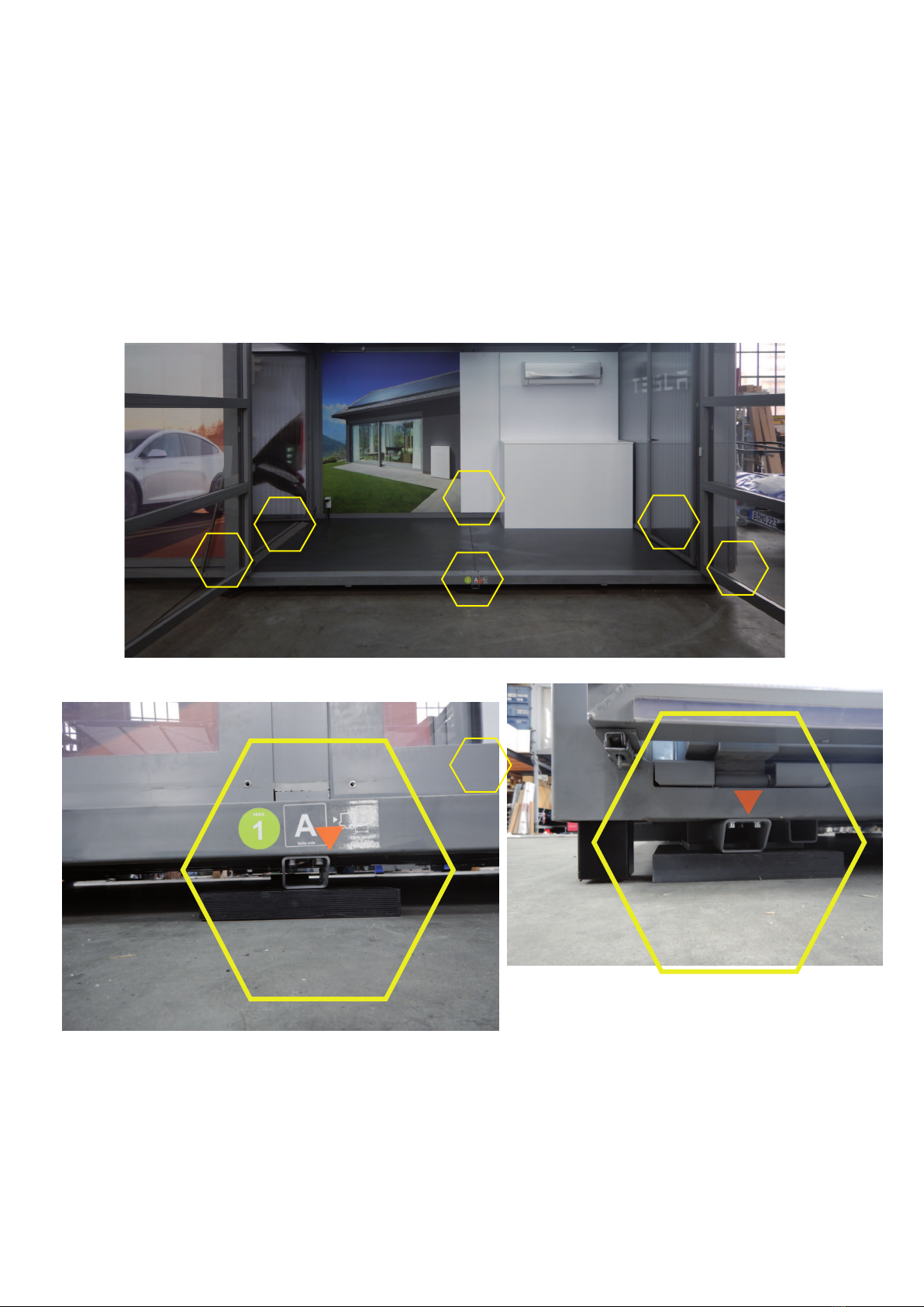
Emergency control
The relays of the motor control are equipped with additional switches.
These are located next to the failure monitors inside the modulbox in a
plastic housing. If the feed to the switching element is damaged or has
failed, the modulbox can be moved by pressing the appropriate button
Generators
When using generators, only high-quality devices that emit a perfect
sinusoidal signal should be used. Otherwise the failure monitoring can
be damaged.
Recommendation: 2x Honda 2.0 EUi, connected via parallel cable
Lifting system checklist
If the drives do not run, check the following points:
> Check the fuse of the power supply
> Maintain a cable length of max. 30m, unroll the drums
> Check the emergency stop on the control
> Check for any cable breaks
> The drives are to be controlled via the emergency control described