Plockmatic BM 82 Installation manual

Provided By
http://www.MyBinding.com
http://www.MyBindingBlog.com
Plockmatic BM 82
Bookletmaker
Operation Manual
Stapler-Folder Model 82
Operator Manual
February 2003
Part No 76174


Stapler Folder Model 82 Operator Manual
T10136
Table of contents
1. Introduction
2. Getting to know the Model 82
2.1 Main components
2.2 The control panel
3. Operating and finishing modes
3.1 The operating modes
3.2 The finishing modes
3.3 Jam indications
4. Operatorinstructions
4.1 Connecting the Model 82 to a collator
4.2 Setting / Changing paper size
4.3 Adjusting the Stacker
4.4 Beginningtheproduction
5. Maintenance
5.1 Replacing the Staple cartridge
5.2 Removing Stapler head / clearing staple jam
5.3 Lubrication of Clinchers and Stapler Head
5.4 Cleaning of Fold rollers
5.5 GFI function test and resetting
6. Troubleshooting
7. Specifications
i

Stapler Folder Model 82 Operator Manual
T10136
Operational safety
This operator manual describes how to operate the Stapler-folder
Model 82 on-line together with collator Models 300/400, Model 100 or
as a stand alone unit.
1. Introduction
Always connect the equipment to a properly
grounded power source receptacle. In doubt,
have the receptacle checked by a qualified
electrician.
WARNING: Improper connection of the equip-
ment grounding conductor can result in electri-
cal shock.
Always follow all warnings marked on, or sup-
plied with, the equipment.
Always locate the equipment on a solid support
surface with adequate strength for the weight of
the machine.
Always exercise care in moving or relocating
the equipment.
Always keep magnets and all devices with
strong magnetic field away from the machine.
Never use a ground adapter plug to connect
the equipment to a power source receptacle
that lacks a ground connection terminal.
Never attempt any maintenance function that is
not specifically described in this documentation.
Never remove the covers or guards that are
fastened with screws.
Never install the unit near a radiator or any
other heat source.
Never override or “cheat” electrical or
mechanical interlock devices.
Never operate the equipment if you notice
unusual noises or odors. Disconnect the power
cord from the power source receptacle and call
your customer service engineer to correct the
problem.
Attention to the following notes ensures the continued safety operation of your equipment.
1-1

Stapler Folder Model 82 Operator Manual
T10136
10
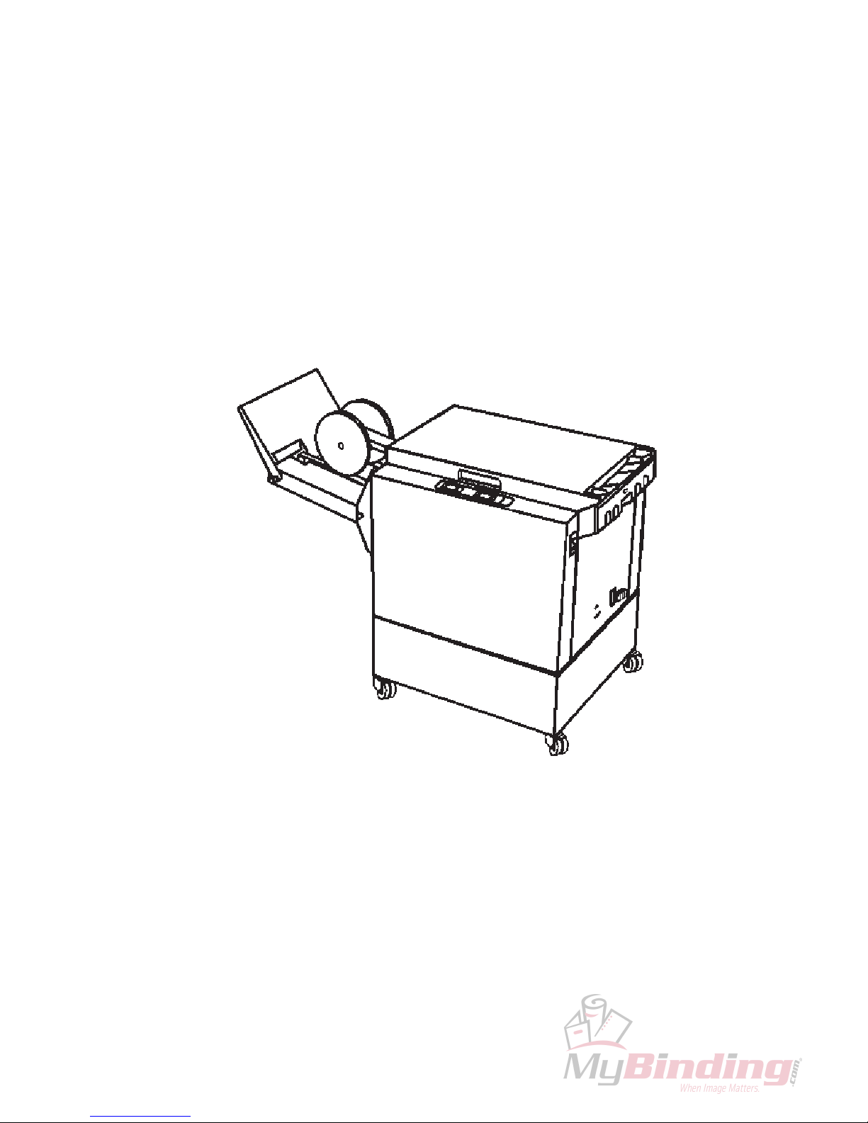
2. Getting to know the Model 82
Takea fewminutes tobecome familiar withthe maincomponents
ofthe Model82.
1. Output wheels 7. Power switch
2. Belt stacker 8. Ground fault interruptor (GFI )
3. Control panel 9. Power cord receptacle incl. fuses
4. Top cover 10. Connection cable outlet
5. Docking assembly 11. Base
6. Back jogger adjustment screw
2.1 Main components
2
3
4
5
7
8
9
1
11
2-1
6
Stapler Folder Model 82 Operator Manual
T10136
1
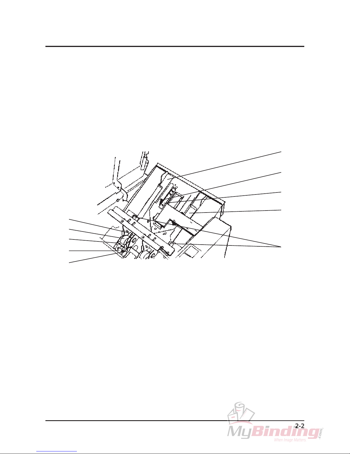
2.1 Main components cont.
1. Stapler head 6. Rear Side guide
2. Staple cartridge 7. Back jogger
3. Cartridge locking lever 8. Scale, length adjustment
4. Stapler release latch 9. Front Side guide
5. Staple detection lead 10. Release handle, Side guide
2
3
4
5
6
7
8
9
10
Whensetting upthe Model 82 or performingmaintenance itis
sometimesrequiredto moveinternal components ofthe machine.
Take afew minutes tobecome familiarwith these components.
2-2

Stapler Folder Model 82 Operator Manual
T10136
1
2.2 Control panel
1. Auto mode indicator 9. Stacker full indicator
2. Manual mode indicator 10. Staple(s) missing indicator
3. Staple and fold mode indicator 11. Manual / Auto mode button
4. Fold mode indicator 12. Program select button
5. Edge stapling mode indicator 13. Run / Adjustment mode button
6. Run mode indicator 14. Length adjustment button, decrease
7. Adjustment mode indicator 15. Length adjustment button, increase
8. Paper jam indicator
23 645 7 8910
11 12 13 14 15
2-3
Stapler Folder Model 82 Operator Manual
T10136
3. Operating and finishing modes
TheModel 82 canbe operated inseveral combinations ofmodes.
Thesemodes aretwo operatingmodes and threefinishing
modes.In this sectionwe will explainthe different modesand how
theyareselected.
3.1 The operating modes
3.2 The finishing modes
3-1
Thethreefinishing modesare:
1. Edge stapling
Whenselecting thismode by pressingthe Programselect
buttontheset willexitat the loweroutputarea.Adeliverytrayfor
edge stapled sets is available, part no. 750004.
IfaTrimmeris installedto yourModel 82, remove the scrappaper
binto allow theedge stapledsetsto enterthe delivery traywhich
isintegrated inthe baseof theTrimmer.
2. Fold only
Whenselecting this modeby pressingtheProgram selectbutton,
thestapler actionis switched off and thefolded setwill exitat the
upperoutputarea ontothebelt stacker.
3. Saddle stapling and fold
Whenselecting this modeby pressingtheProgram selectbutton,
thestapled andfoldedsets willexit attheupper outputarea onto
thebeltstacker.
Thetwo operatingmodes are:
1. Manual mode
SelectManual mode ifoperating the Model82 as astand alone
unit,forhandfeeding.
TheManual modeis selectedwhen theMAN LEDis lit.
Pressthe Manual /Automodebutton tochangeoperating mode.
2. Automatic mode
SelectAutomaticmode if operating theModel 82together witha
collatorasan on-line system.
TheAutomaticmode isselected whentheAUTOLEDis lit.
Pressthe Manual /Automodebutton tochangeoperating mode.
Note: If in manual mode when the on-line connected collator starts, the
mode will automatically switch from Manual to Automatic mode, to
preventinterruptions.

Stapler Folder Model 82 Operator Manual
T10136
3.3 Jam indications
1. Staple(s) missing indicator
TheStaple(s) missingindicator isilluminated whena setis
missingone or twostaples. TheModel82 willautomatically
stopthe on-linesystem when thisindicator LEDis lit.
Uponindication afterloading anew staplecartridge, open
andclose the Topcover.TheModel82 willnow cycle and
advancestaples onthe sameset fora maximumof 5
staplingcycles or untilstaples are resumed.Replacing the
staple cartridge is described in section 5.
2. Stacker full indicator
TheStackerfullindicator islit when thebelt stackerorthe
deliverytray is full.Remove the finishedsets.Assoonasthe
stackerfull sensoris clear theindication willgo off. The
Model82will automatically stoptheon-line system whenthis
indicatorLED is lit.All setsalready fedfrom the Collatorwill
beprocessed until fullstoppage.
3. Paper jam indicator
ThePaper jamindicator is illuminatedwhen anoperation in
theModel 82is not done within thepreset time.Open the
topcover andremovethe jammedsets reachable,closethe
topcover and theModel 82willautomatically purge
remainingjammed sets. Model82 willautomaticallystop the
on-linesystem whenthisindicator LEDis lit.
3-2
Table of contents


