manuals.online logo
Brands
  1. Home
  2. •
  3. Brands
  4. •
  5. OCEE DESIGN
  6. •
  7. Office Equipment
  8. •
  9. OCEE DESIGN DEN.Cube User manual

OCEE DESIGN DEN.Cube User manual

Assembly Instructions
DEN.Cube
2 Person
1400w & 1600w odule
SASS-0070 A
850w Side Panel
A x2 1400w Den.Cube = 1050w Back Panel
1600w Den.Cube = 1250w Back Panel
2-Way Junction (90°)
Bottom Connector Link
C x2B x2
Z x10
1400w Den.Cube = 1300w Worksurface
1600w Den.Cube = 1500w Worksurface
G x2 6x20 Button Head Bolts
Large Worksurface Fixing Bracket Small Worksurface Fixing Bracket
W x44
X x6 Y x6
Return Worksurface
H x2
Worksurface Components
Shell Components
650w Side Panel
E x2
Junction Connector Plate
S x2
1250w Back Panel
D x1
3-Way Junction (90°)
F x2
DEN.Cube Assembly Instructions DWG No: SASS-0070
Revision: A (02/11/15)
Drawn by: CE
Drawn date: 08/09/15
Tools
4mm Allen Key/Phillips Screwdriver Cushioned allet 13mm Spanner
DEN.Cube Assembly Instructions DWG No: SASS-0070
Revision: A (02/11/15)
Drawn by: CE
Drawn date: 08/09/15
&
Z'HQ&XEH Z%DFN3DQHO
Z'HQ&XEH Z%DFN3DQHO
$
Z6LGH3DQHO
'
Z%DFN3DQHO
(
Z6LGH3DQHO
&
Z'HQ&XEH Z%DFN3DQHO
Z'HQ&XEH Z%DFN3DQHO
(
Z6LGH3DQHO
$
Z6LGH3DQHO
=
%RWWRP&RQQHFWRU
/LQN[
%
:D\-XQFWLRQ

<
;
<
;
;
/DUJH:RUNVXUIDFH
)L[LQJ%UDFNHW
<
6PDOO:RUNVXUIDFH
)L[LQJ%UDFNHW
%
:D\-XQFWLRQ

)
:D\-XQFWLRQ

*
Z'HQ&XEH Z:RUNVXUIDFH
Z'HQ&XEH Z:RUNVXUIDFH
6
-XQFWLRQ&RQQHFWRU
3ODWH
+
5HWXUQ
:RUNVXUIDFH
)
:D\-XQFWLRQ

6
;
<<
;
;
<
*
Z'HQ&XEH Z:RUNVXUIDFH
Z'HQ&XEH Z:RUNVXUIDFH
+
5HWXUQ
:RUNVXUIDFH
%
%
)
$
(
)
&
'
(
$
*
*
+
&
Assembled Configuration Illustration (for Reference)
DEN.Cube Assembly Instructions DWG No: SASS-0070
Revision: A (02/11/15)
Drawn by: CE
Drawn date: 08/09/15
1.
Insert the modular screws in the 850w side panel (A-1) into the keyholes in the 2-way
junction (B-1), making sure that all of the screws have engaged into the keyholes.
2.
After making sure all of the screws are engaged in the keyholes, tap the top of the
850w side panel (A-1) with a cushioned mallet to fully engage. Tie the 850w side
panel (A-1) and the 2-way junction (B-1) together using a bottom connector link (Z).
Insert this over one of the levellers (between the nut and the bottom of the
panel/junction) in the hooked slot and pivot around to insert the other leveller into the
straight slot. Fully tighten both nuts using a 13mm spanner to trap the connector.
3.
Attach the 1050w/1250w (module dependent) back panel (C-1) to the 2-way junction
(B-1) as shown above (see step 1 for method).
4.
Tap the top of the 1050w/1250w (module dependent) back panel (C-1) with a
cushioned mallet to fully engage.
Tie the 1050w/1250w (module dependent) back panel (C-1) to the 2-way junction
(B-1) using a bottom connector link (Z) as shown above (see step 2 for method).
Panel
Connector
8 nut
Leveller
Sub-Assembly A
Panel
Connector
8 nut
Leveller
Junction
Z
Bottom Connector Link
B-1
2-Way Junction (90°) A-1
850w Side Panel
C-1
1400w Den.Cube = 1050w Back Panel
1600w Den.Cube = 1250w Back Panel
Z
Bottom Connector Link
DEN.Cube Assembly Instructions DWG No: SASS-0070
Revision: A (02/11/15)
Drawn by: CE
Drawn date: 08/09/15
5.
Attach the 1050w/1250w (module dependent) back panel (C-1) to the 3-way junction
(F-1) as shown above (see step 1 for method).
6.
Tap the top of the 1050w/1250w (module dependent) back panel (C-1) with a cushioned
mallet to fully engage.Tie the 1050w/1250w (module dependent) back panel (C-1) to the
3-way junction (F-1) using a bottom connector link (Z) (see step 2 for method).
You have now fully assembled sub-assembly A, safely secure this sub-assembly until
step 13 where it shall be used in the main assembly of the cube.
7.
Attach the 650w side panel (E-1) to the 3-way junction (F-2) as shown above (see
step 1 for method).
8.
Tap the top of the 650w side panel (E-1) with a cushioned mallet to fully engage.
Tie the 650w side panel (E-1) to the 3-way junction (F-2) using a bottom connector
link (Z) (see step 2 for method).
Sub-Assembly B
DEN.Cube Assembly Instructions DWG No: SASS-0070
Revision: A (02/11/15)
Drawn by: CE
Drawn date: 08/09/15
F-1
3-Way Junction (90°) Z
Bottom Connector Link
F-2
3-Way Junction (90°)
Z
Bottom Connector Link
E-1
650w Side Panel
9.
Attach the 1250w back panel (D-1) to the 3-way junction (F-2) as shown above (see
step 1 for method).
10.
Tap the top of the 1250w back panel (D-1) with a cushioned mallet to fully engage.
Tie the 1250w back panel (D-1) to the 3-way junction (F-2) using a bottom connector
link (Z) (see step 2 for method).
11.
Attach the 650w side panel (E-2) to the 3-way junction (F-2) as shown above (see
step 1 for method).
12.
Tap the top of the 650w side panel (E-2) with a cushioned mallet to fully engage.
Tie the 650w side panel (E-2) to the 3-way junction (F-2) using a bottom connector
link (Z) (see step 2 for method).
You have now fully assembled sub-assembly B, safely secure this sub-assembly until
step 13 where it shall be used in the main assembly of the cube.
DEN.Cube Assembly Instructions DWG No: SASS-0070
Revision: A (02/11/15)
Drawn by: CE
Drawn date: 08/09/15
D-1
1250w Back Panel
Z
Bottom Connector Link
Z
Bottom Connector Link
E-2
650w Side Panel
13.
Attach the 1250w back panel (D-2) of sub-assembly B to the 3-way junction (F-1) of
sub-assembly A (see step 1 for method).
14.
Tap the top of the 1250w back panel (D-2) of sub-assembly B with a cushioned mallet to
fully engage. Tie the 1250w back panel (D-2) of sub-assembly B to the 3-way junction
(F-1) of sub-assembly A using a bottom connector link (Z) (see step 2 for method).
Safely secure this sub-assembly of panels until step 19 where it shall be used in the
main assembly of the cube.
15.
Attach the 850w side panel (A-2) to the 2-way junction (B-2) as shown above (see
step 1 for method).
16.
Tap the top of the 850w side panel (A-2) with a cushioned mallet to fully engage. Tie
the 850w side panel (A-2) to the 2-way junction (B-2) using a bottom connector link
(Z) (see step 2 for method).
Sub-assembly B
Sub-assembly A
Sub-Assembly C
DEN.Cube Assembly Instructions DWG No: SASS-0070
Revision: A (02/11/15)
Drawn by: CE
Drawn date: 08/09/15
Z
Bottom Connector Link
A-2
850w Side Panel
Z
Bottom Connector Link
B-2
2-Way Junction (90°)
17.
Attach the 1050w/1250w (module dependent) back panel (C-2) to the 2-way junction
(B-2) as shown above (see step 1 for method).
18.
Tap the top of the 1050w/1250w (module dependent) back panel (C-2) with a cushioned
mallet to fully engage. Tie the 1050w/1250w (module dependent) back panel (C-2) to the
2-way junction (B-2) using a bottom connector link (Z) as shown above (see step 2 for
method).
You have now fully assembled sub-assembly C, safely secure this sub-assembly until step
19 where it shall be used in the main assembly of the cube.
19.
Attach the 1050w/1250w (module dependent) back panel (C-2) of sub-assembly C to
the 3-way junction (F-1) of the panel assembly from step 14 (see step 1 for method).
20.
Tap the top of the 1050w/1250w (module dependent) back panel (C-2) with a
cushioned mallet to fully engage.
Tie the 1050w/1250w (module dependent) back panel (C-2) of sub-assembly C to the
3-way junction (F-1) using a bottom connector link (Z) (see step 2 for method).
Sub-assembly C
DEN.Cube Assembly Instructions DWG No: SASS-0070
Revision: A (02/11/15)
Drawn by: CE
Drawn date: 08/09/15
C-2
1400w Den.Cube = 1050w Back Panel
1600w Den.Cube = 1250w Back Panel
Z
Bottom Connector Link
Z
Bottom Connector
Link
200
200
200
25
250
C
L
W
M6 x 20mm Button
Head Bolts
(x9)
21.
Attach the worksurface fixing brackets (X&Y) to the Den structure using 1x 6x20mm socket button head machine screw (W) per small bracket (Y) and 2x 6x20mm socket button
head machine screws (W) per large bracket (X), in the positions shown above. Use the top holes/slots for a 730mm worksurface height and the bottom for a 750mm worksurface
height. (see above)
When fixing the small brackets (Y) to the structure, make sure to pass the machine screws (W) through the 7mm hole. When fixing the Large brackets (X) to the structure, make sure
to pass the machine screws (W) through the horizontal slot.
22.
Lower the worksurfaces (G&H) onto the brackets (X&Y) attached to the structure in
steps 13. Attach the worksurface fixing brackets (X&Y) to the underside of the
worksurfaces (G&H) using 1x 6x20mm socket button head machine screw (W) per
small bracket (Y) and 2x 6x20mm socket button head machine screws (W) per large
bracket (X).
23.
750mm Worksurface
height
XY
730mm Worksurface
height FRONT
BACK
FRONT
BACK
FRONT
BACK
X
X
X
Y
YY
4mm Allen Key
Y
Small Worksurface
Fixing Bracket
X
Large Worksurface
Fixing Bracket
W
6x20 Button
Head Bolts
W
W
W
W
W
W
W
W
W
DEN.Cube Assembly Instructions DWG No: SASS-0070
Revision: A (02/11/15)
Drawn by: CE
Drawn date: 08/09/15
To secure the 2 worksurfaces (G&H), attach the junction connector plate (S), using
4x 6x20mm socket button head machine screws (W), in the position shown above.
Repeat steps 21 - 23 for both units.
W
W
W
W
W
WW
W
W
H -1
Return
Worksurface
G-1
1400w Den.Cube = 1300w Worksurface
1600w Den.Cube = 1500w Worksurface
4mm Allen Key
W
6x20 Button
Head Bolts
Y
Small Worksurface
Fixing Bracket
X
Large Worksurface
Fixing Bracket Underside
View
W
S

Other manuals for DEN.Cube

1

Other OCEE DESIGN Office Equipment manuals

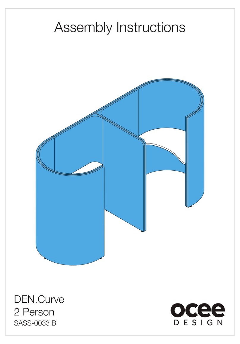
OCEE DESIGN DEN.Curve 2 Person User manual

OCEE DESIGN

OCEE DESIGN DEN.Curve 2 Person User manual

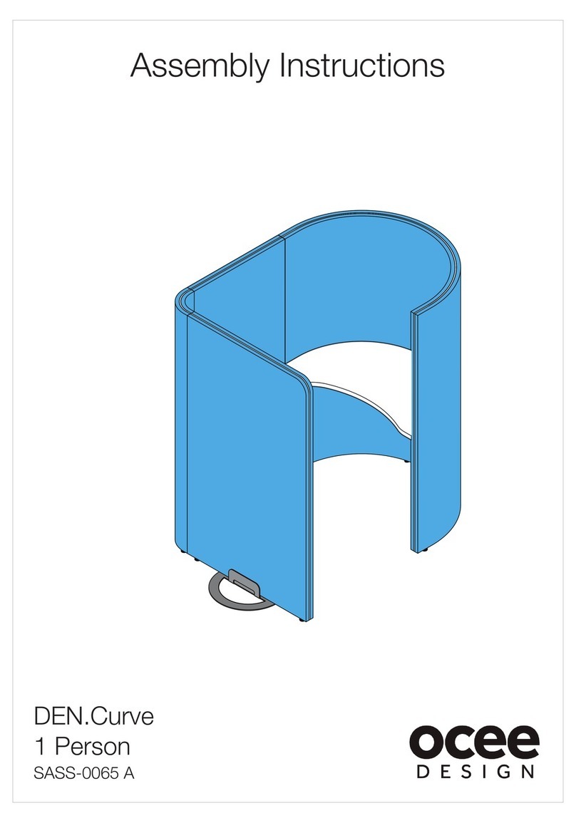
OCEE DESIGN DEN.Curve User manual

OCEE DESIGN

OCEE DESIGN DEN.Curve User manual

OCEE DESIGN SASS-0102 User manual

OCEE DESIGN

OCEE DESIGN SASS-0102 User manual

OCEE DESIGN SASS-0090 User manual

OCEE DESIGN

OCEE DESIGN SASS-0090 User manual

OCEE DESIGN DEN SASS-0081 User manual

OCEE DESIGN

OCEE DESIGN DEN SASS-0081 User manual

OCEE DESIGN Den Seat SASS-0079 A User manual

OCEE DESIGN

OCEE DESIGN Den Seat SASS-0079 A User manual

OCEE DESIGN SASS-0096 User manual

OCEE DESIGN

OCEE DESIGN SASS-0096 User manual

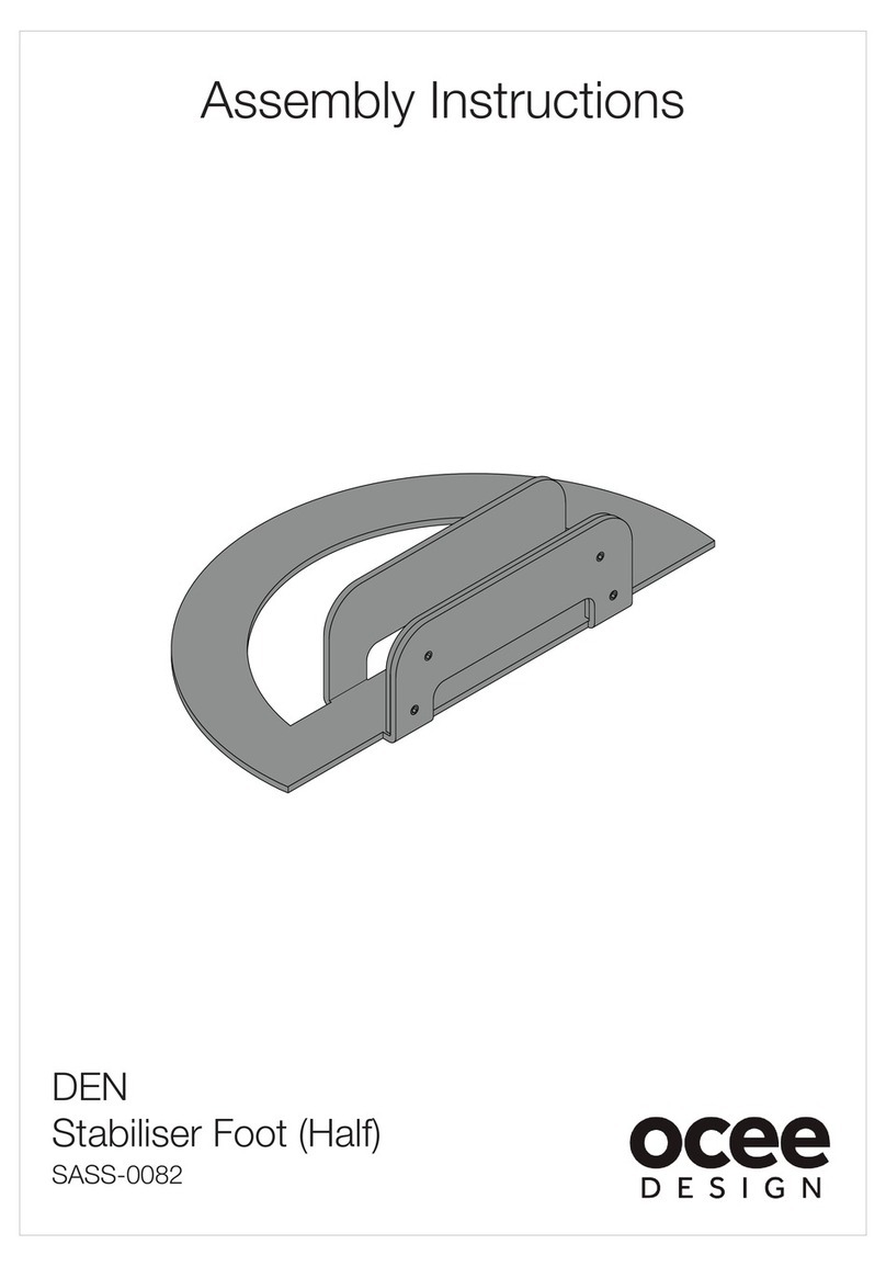
OCEE DESIGN DEN SASS-0082 User manual

OCEE DESIGN

OCEE DESIGN DEN SASS-0082 User manual

OCEE DESIGN DEN.Booth SASS-0040 B User manual

OCEE DESIGN

OCEE DESIGN DEN.Booth SASS-0040 B User manual

OCEE DESIGN DEN.Panel Triple SASS-0068 A User manual

OCEE DESIGN

OCEE DESIGN DEN.Panel Triple SASS-0068 A User manual

OCEE DESIGN SASS-0100 User manual

OCEE DESIGN

OCEE DESIGN SASS-0100 User manual

OCEE DESIGN DEN 675d Module User manual

OCEE DESIGN

OCEE DESIGN DEN 675d Module User manual

Popular Office Equipment manuals by other brands

Hasler HJOG1011 operating guide

Hasler

Hasler HJOG1011 operating guide

Herman Miller Canvas Office Landscape Installation and Disassembly for Recycling Instructions

Herman Miller

Herman Miller Canvas Office Landscape Installation and Disassembly for Recycling Instructions

Jason.L San Fran 3 Person Run Workstation installation guide

Jason.L

Jason.L San Fran 3 Person Run Workstation installation guide

Langle AL-OFFICE NY Assembly instructions

Langle

Langle AL-OFFICE NY Assembly instructions

aidapt VM961 Usage and maintenance instructions

aidapt

aidapt VM961 Usage and maintenance instructions

hushoffice hushwork.sit&stand HUS-BX-016/116 Maintenance and safety manual

hushoffice

hushoffice hushwork.sit&stand HUS-BX-016/116 Maintenance and safety manual

Plus K-10S Service manual

Plus

Plus K-10S Service manual

Siemens HIPATH 2000 user guide

Siemens

Siemens HIPATH 2000 user guide

Wiremold V2400 Series installation instructions

Wiremold

Wiremold V2400 Series installation instructions

Ergotron Neo-Flex WideView WorkSpace Assembly instructions

Ergotron

Ergotron Neo-Flex WideView WorkSpace Assembly instructions

Morgana FRN 5 Operator's guide

Morgana

Morgana FRN 5 Operator's guide

ONELAN Reserva Edge 10T-W quick start guide

ONELAN

ONELAN Reserva Edge 10T-W quick start guide

Kimball Office Footprint Assembly instructions

Kimball Office

Kimball Office Footprint Assembly instructions

Secap SI5400 Operator's guide

Secap

Secap SI5400 Operator's guide

Panasonic Panafax UF-9000 Service handbook

Panasonic

Panasonic Panafax UF-9000 Service handbook

Reiner jetStamp graphic 970 Short Instruction

Reiner

Reiner jetStamp graphic 970 Short Instruction

ESI FlexCharge9 FCH9-POD-WHT Assembly and operation instructions

ESI

ESI FlexCharge9 FCH9-POD-WHT Assembly and operation instructions

Steelcase Elective Elements Freestanding Corner... manual

Steelcase

Steelcase Elective Elements Freestanding Corner... manual

manuals.online logo
manuals.online logoBrands
  • About & Mission
  • Contact us
  • Privacy Policy
  • Terms and Conditions

Copyright 2025 Manuals.Online. All Rights Reserved.