8
mo systeme GmbH & Co.KG
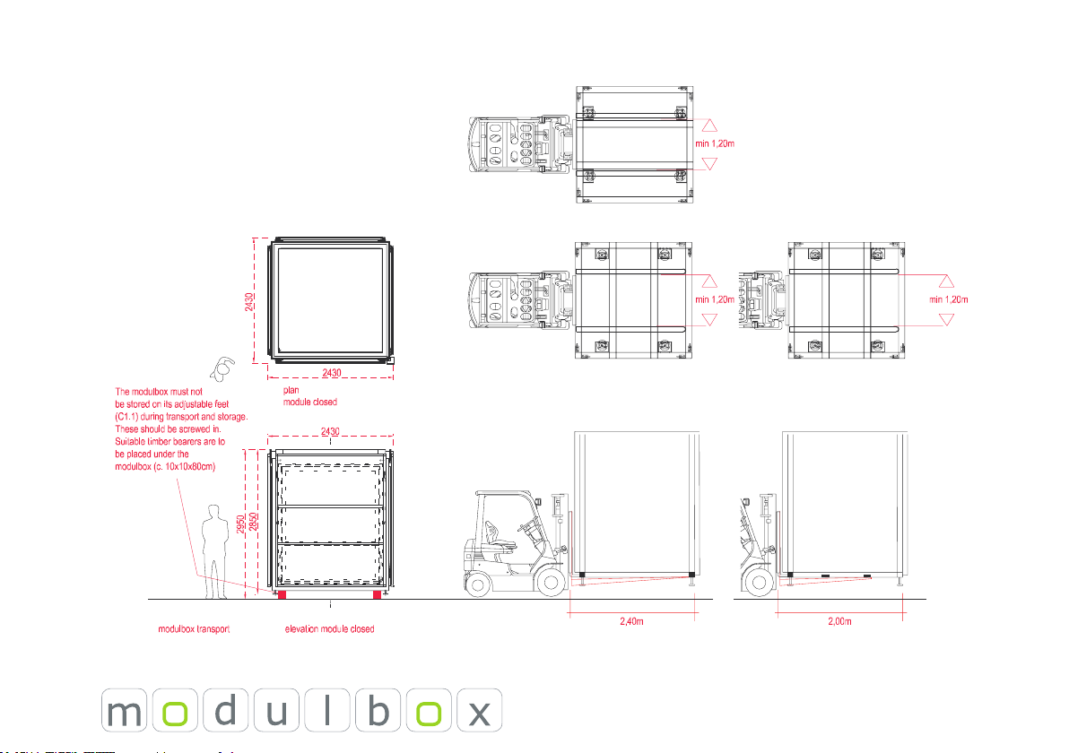
C. Transport and Installation
The modulbox has to be set up horizontally so
that any rain water can be channelled away at the
lowest point. Do not open the modulbox during a
storm. Further usage instructions are to be found
in the section ‘Warnings’ and the introduction to
use.
C.1 Transport with truck and fork-lift
The modulbox has a total height of 2.85m and a
weight of up to 2t per modulbox, depending on
ttings. These data should determine the choice of
transport vehicle and fork-lift (load centre).
The transport vehicle has to have a suitable load
height (Jumbo Roller).
During transport on an open vehicle the
modulbox should be covered with a transport
cover (special ttings).
When using a protective cover during transport,
protect the corner of the rain tube in order to
ensure that the cover is not ripped.
Fork-lift trucks whose forks are a minimum of
2.00m long can lift the modulbox from two sides
(the two sides marked with the sticker). (C1.3).
In this case it is important to place the modulbox
on the transport vehicle in such a way that it can
be unloaded from the same side – see Figure.
If the forks are longer than 2.40m, the modulbox
can be lifted from all four sides.
The modulbox must not be stored on its
adjustable feet (C1.1) during transport and
storage. These should be screwed in. Suitable
timber bearers are to be placed under the
modulbox (c. 10x10x80cm) (C1.2).
When on the transport vehicle, the modulbox
must be tightly secured so as to prevent any
movement. Securing straps should be fastened to
the fastening points. Four securing straps must be
used for each modulbox (one at each corner).
Alternatively, securing straps can be attached from
the oor points on the truck over the attic sheeting
of the modulbox. If so, careful attention must be
paid that the securing straps do not damage the
foldable roof parts.
Check every installation site for the modulbox
very carefully. Make certain that the ground is rm
enough to bear the modulbox. On soft ground
the modulbox must be placed on load-distributing
stone slabs or steel plates. Bear in mind that,
depending upon use, a load of up to one ton must
be borne by each of the feet.
External measurements of the modulbox
Length x width x height
2.46m x 2.46 x 2.85
Weight: up to 2t gross weight