Mayline XR User manual

Table of Contents Page
XR Installation Instructions
Modesty Panel to Dual XR Base............................................................................... 2
Modesty Panel to Triple XR Base............................................................................. 3
Dual Column XR Base.............................................................................................. 4
Desk Switch with Programmable Memory................................................................. 5
Triple Column XR Base............................................................................................. 6

ASSEMBLY INSTRUCTIONS for
MODESTY PANEL to DUAL XR BASE
HARDWARE:
A. 1/4-20 x 1/2 Screw.......4
B. 1/4-20 KEPS Nut..........4
1. Position the notches in the Modesty Panel
flanges toward the floor.
2. Place the Modesty Panel over the Base
Cross Channel, resting the modesty panel
on the top flange of the cross channel.
3. Insert 1/4-20 x 1/2 Screws (A) through
two of the aligned Modesty Panel and Cross
Channel holes per side. Use the outer most
accessible holes.
4. Secure in place with two KEPS Nuts (B)
per side.
Modesty Panel
Notches DOWN
Cross Channel

ASSEMBLY INSTRUCTIONS for MODESTY
PANELS to TRIPLE XR BASE
HARDWARE:
A. 1/4-20 x 1/2 Screw.......4
B. 1/4-20 KEPS Nut..........4
To install Modesty panels on the three
column base, some existing hardware wll
be used. Install the Modesty Panel to
ONE side of the base at a time.
1. Remove four screws from ONE Cross
Channel at the center/rear column, these
screws and nuts will be reused.
2. Position the notches in the Modesty
Panel flanges toward the floor.
3. Place the Modesty Panel over the Base
Cross Channel, resting the modesty panel
on the top flange of the cross channel.
4. Insert two 1/4-20 x 1/2 Screws through
two of the aligned Modesty Panel, Cross
Channel, and Bracket holes at the
center/rear column. Secure in place with
two KEPS Nuts.
5. Insert two 1/4-20 x 1/2 Screws (A)
through two of the aligned Modesty Panel
and Cross Channel holes near the outer
column. Secure in place with two KEPS
Nuts (B).
6. Insert two additional 1/4-20 x 1/2
Screws through the aligned holes at the
center/rear column and secure them in
place with two KEPS Nuts.
7. Repeat these steps for the other
Modesty Panel.
Cross Channel
Modesty Panel
Notches DOWN
Use these
fasteners again

1. Place each Column Assembly (A) upside down with the
cord toward the floor.
2. Position the Leg (B) over Column Assembly (A) with the
longer portion of the Leg toward the front. The column front
is determined by the cross channel clip that is welded on the
column, position this clip to the rear.
3. Attach the Leg (B) to the Column Assembly (A) with four
M6 x 16 mm Screws (J) and Star Washers (K).
4. Screw the Glides (L) into the two tapped holes in the
bottom of each Leg (B).
5. Place the assembled columns upright and attach the
Cross Channel (C). Position the Cross Channel flange with
end notches toward the floor. Slide the Cross Channel
bracket into the tapered channel clip on each Column.
Gently tap the Cross Channel in place with a Rubber Mallet
to assure a tight fit.
6. Gently remove the cord and strain relief from the notch in
the top of the Column Assembly (A). Position the cords so
that they are toward the center of the assembled base.
Insert the strain relief into the appropriate Column notch.
Attach Top Plate (D) to each Column with four M6 x 16 mm
Screws (J) and Star Washers (K).
7. Attach the Switch (F), Power Cord (G), and Connector
Cables (H) to the Control Box (E).
8. PRIOR TO ATTACHING A WORKSURFACE.
Place the Switch cable over the top of the Cross Channel.
ASSEMBLY INSTRUCTIONS
for DUAL COLUMN XR BASE
COMPONENTS:
A. Column Assembly.....2
B. Leg............................2
C. Cross Channel..........1
D. Top Plate...................2
E. Control Box...............1
F. Switch........................1
G. Power Cord...............1
H. Connector Cable.......2
HARDWARE:
J. M6 x 16 mm Screw...16
K. Star Washer.............16
L. Glide...........................4
M. #10 x 3/4 Screw.......15
N. #6 x 5/8 Screw...........2
P. Cable Clamp..............3
Cross Channel clip
on REAR of Column
Cord
Cords toward
center
Cross Channel
notches DOWN
Cross Channel
notches DOWN
Switch cable OVER
Cross Channel

1. Initialize system by pressing down and holding for 5 to 10
seconds after table bottoms out.
2. Push 'UP' to desired height.
3. To save this position in Memory:
A.) Press (Set)
B.) Press (do not hold) button , , or
Position is now saved under the number chosen.
4. To change to different height, press or .
This position may be saved by repeating Step 3 and using
one of the other buttons or using the same button to change
the previous setting. Up to 3 positions may be stored.
5. To go to new height position, press or , or press stored
height under , , or . Unit will automatically stop at
the stored position.
S
1 2 3
1 2 3
INSTRUCTIONS for
DESK SWITCH w/ PROGRAMMABLE
MEMORY
21 S3
11. Align the holes in the Top with the holes in the Mounting Plates and secure
in place with eight #10 x 3/4 Screws (M).
12. Align the holes in the Control Box with the holes in the underside of the
Top and attach it with four #10 x 3/4 Screws (M). Connect the cables to the
columns.
13. Place the Switch in a comfortable and accessible location on the underside
of the Top and attach it with two #6 x 5/8 Screws (N).
14. Route the column cables and the switch cable away from moving
components and secure them in place with Cable Clamps (P) and Screws (M).

1. Place each Column Assembly (A) upside down with the cord
toward the floor.
2. Position the Leg (B or C) over Column Assembly (A) with the
longer portion of the Leg toward the front (Corner Leg is
symmetrical). The column front is determined by the cross
channel clip that is welded on the column, position this clip to
the rear.
3. Attach the Leg (B or C) to the Column Assembly (A) with four
M6 x 16 mm Screws (M) and Star Washers (N).
4. Screw the Glides (P) into the two tapped holes in the bottom
of each Leg (B and C).
5. Place the assembled Corner Column upright and attach the
Corner Bracket (F). Slide the Corner Bracket into the tapered
channel clip on the column. Gently tap Bracket in place with a
Rubber Mallett to assure a tight fit.
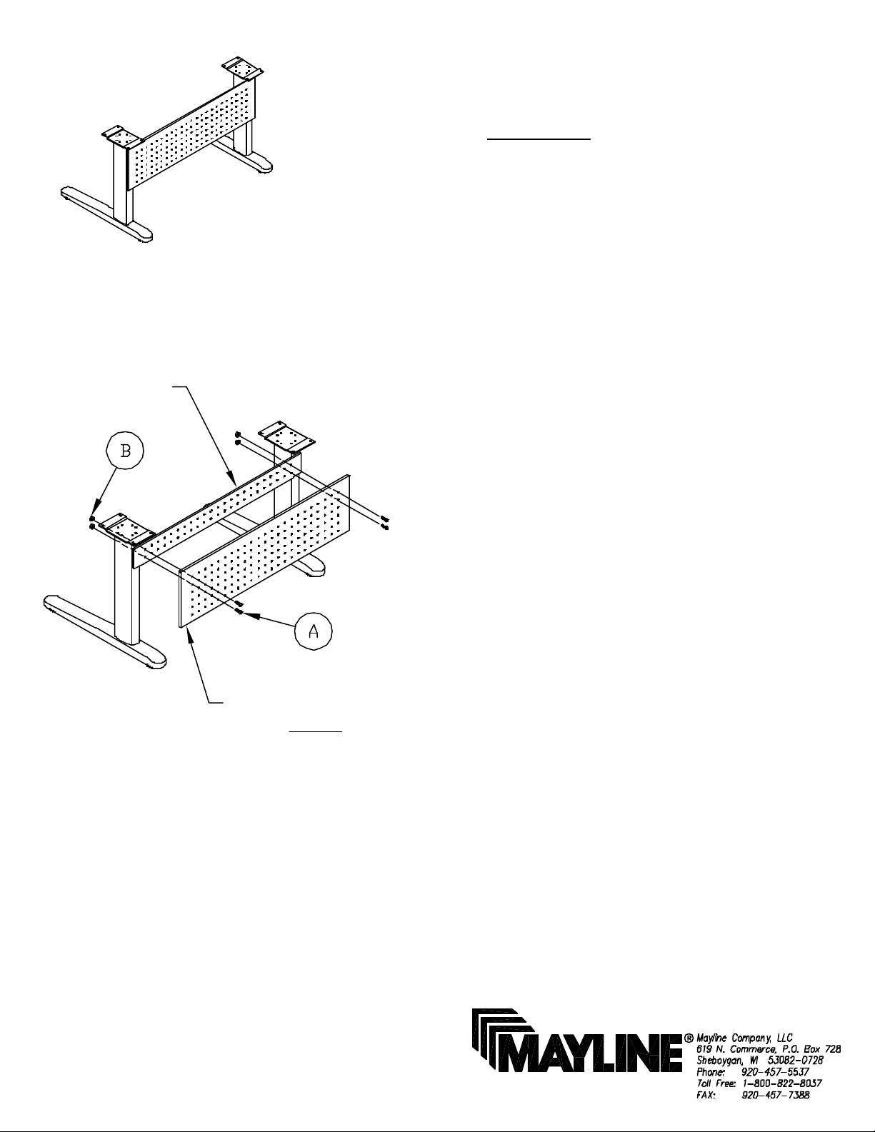
6. Place the outer assembled columns upright and attach the
Cross Channels (D). Position the Cross Channel flange with
end notches toward the floor. Slide the Cross Channel bracket
into the tapered channel clip on each Column. Gently tap the
Cross Channel in place with a Rubber Mallet to assure a tight
fit.
7. Align the last 4 holes in each Cross Channel with the 4 holes
in the Corner Bracket mounted to the Corner Column and
attach with four 1/4-20 X 1/2 Screws (Q) and KEPS Nuts (R).
ASSEMBLY INSTRUCTIONS for
TRIPLE COLUMN XR BASE
COMPONENTS:
A. Column Assembly.....3
B. Leg............................2
C. Corner Leg................1
D. Cross Channel..........2
E. Top Plate...................3
F. Corner Bracket..........1
G. Control Box...............1
H. Switch.......................1
J. Power Cord...............1
K. 1000mm Cable..........1
L. 2000mm Cable..........2
HARDWARE:
M. M6 x 16 mm Screw...24
N. Star Washer..............24
P. Glide...........................6
Q. 1/4-20 x 1/2 Screw.....8
R. 1/4-20 KEPS Nut........8
S. #10 x 34 Screw.........20
T. #6 x 5/8 Screw............2
U. Cable Clamp...............4
8. Gently remove the cord and strain relief from the
notch in the top of the Column Assembly (A). Position
the cords so that they are toward the center of the
assembled base. Insert the strain relief into the
appropriate Column notch. Attach Top Plate (E) to
each Column with four M6 x 16 mm Screws (M) and
Star Washers (N).

INSTRUCTIONS for
DESK SWITCH w/ PROGRAMMABLE MEMORY
1. Initialize system by pressing down and holding for 5 to 10
seconds after table bottoms out.
2. Push 'UP' to desired height.
3. To save this position in Memory:
A.) Press (Set)
B.) Press (do not hold) button , , or
Position is now saved under the number chosen.
4. To change to different height, press or .
This position may be saved by repeating Step 3 and using
one of the other buttons or using the same button to change
the previous setting. Up to 3 positions may be stored.
5. To go to new height position, press or , or press stored
height under , , or . Unit will automatically stop at
the stored position.
1 2 3
S1 32
123S
9. Attach the Switch (H), Power Cord (J), and Connector
Cables (K and L) to the Control Box (G).
10. PRIOR TO ATTACHING WORKSURFACE:
Place the switch cord over the top of the Cross Channel.
11. Align the holes in the Top with the holes in the
Mounting Plates and secure in place with twelve #10 x 3/4
Screws (S).
12. Align the holes in the Control Box with the holes in the
underside of the Top and attach it with four #10 x 3/4
Screws (S). Connect the cables to the columns.
13. Place the Switch in a comfortable and accessible
location on the underside of the Top and attach it with two
#6 x 5/8 Screws (T).
14. Route the column cables and the switch cable away
from moving components and secure them in place with
Cable Clamps (U) and Screws (S).
Table of contents
Other Mayline Office Equipment manuals