Renz DTP 340 M User manual

Bedienungsanleitung
Elektrische Stanz - und Perforiermaschine
Operation Manual
Electrical desktop punching machine
Mode d’emploi
Perforeuse électrique
Instrucciones de servicio
Máquina eléctrica de troquelado y de perforado
RENZ DTP 340 M
03 / 2006
971 000003


Bedienungsanleitung
Elektrische Stanz - und Perforiermaschine
RENZ DTP 340 M
Die Maschine und ihre Teile
Abfallschublad
Schnellspann-
schraube
Drehknopf
Randabstand
Hauptschalter
Sicherung
Fußschalter
und
Papieranschlag links
Papieranschlag rechts
Druckstücke
Stanzschacht
Handgriff
Stanzwerkzeug
Schnellspann-
schraube
Handgriff
Halterung für
MBS Module

1. Inbetriebnahme:
Maschine kann sitzend oder stehend bedient werden. Zum Aufstellen einen stabilen Standort wählen. Das
Gerät beidseitig am Maschinenboden fassen und nach oben dem Karton entnehmen.
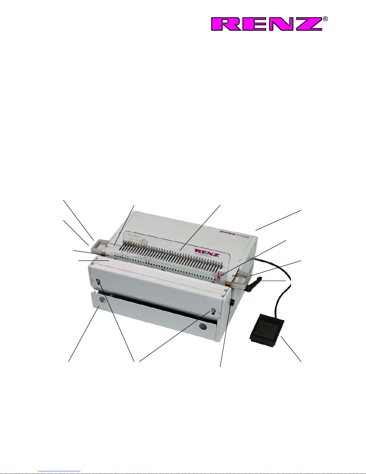
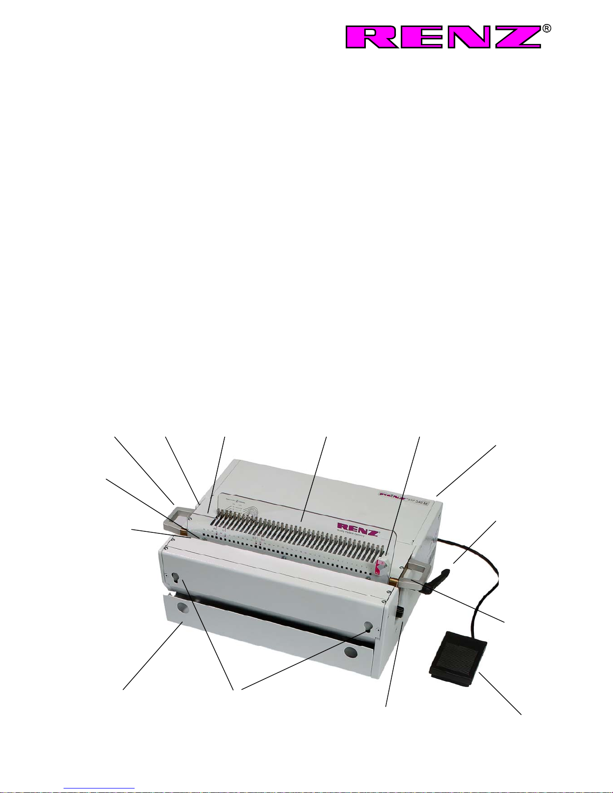
Stecker des Fußschalters und der Gerätezuleitung in die Anschlüsse an der rechten Seitenwand einstecken;
anschließend Stecker an Steckdose anschließen (230 V). Hauptschalter an der rechten Seite des Geräts
einschalten; Kühlventilator läuft. Durch Drücken des Fußschalters wird der Stanzvorgang ausgelöst.
Merke:Motor läuft nur, wenn Pedal gedrückt wird und schaltet dann wieder ab.
Motor läuft nur bei eingebautem Stanzwerkzeug. Ein Sicherheits - Endschalter verhindert bei
ausgebautem Werkzeug ein Anlaufen des Motors.
Achtung:Gewisse Bauteile des Geräts sind aus Rostschutzgründen mit einem entsprechendem Mittel
behandelt. Bitte vor Inbetriebnahme mit einigen Papierblättern mehrere Probestanzungen durchführen, um so
die unvermeidlichen Rückstände des Rostschutzmittels aus dem Stanzschacht und von den Stanzmessern zu
entfernen.
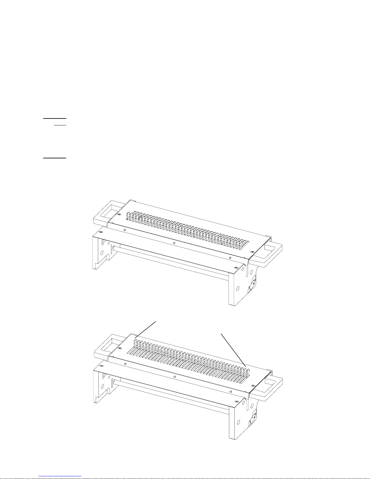
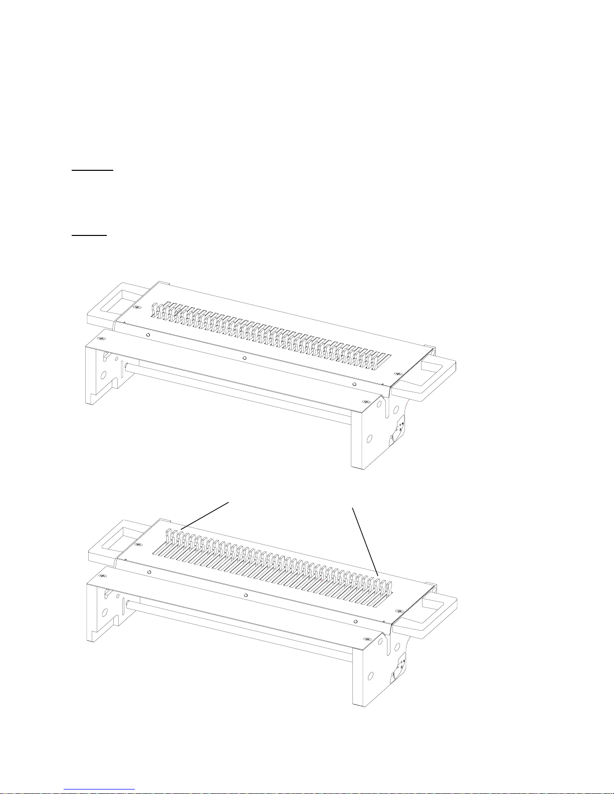
2. Formateinstellung:
DIN A 4 Papieranschlag am rechten Absatz des Anschlagblechs festschrauben.
z.B. RING WIRE®3:1, 4. Druckstück von links hochziehen.
DIN A 5 Papieranschlag am linken Absatz des Anschlagblechs festschrauben.
z.B. RING WIRE®3:1, 4. Druckstück von links hochziehen.
10. Druckstück von rechts hochziehen.
Bei Formaten größer als DIN A 4 durch Niederdrücken der Druckstücke entsprechend mehr Stanzstempel
einschalten und mit Papieranschlag vermitteln.
3. Einstellung des Randabstands:
Mit seitlich rechts angebrachtem Drehkopf den Randabstand der Perforation auf den jeweiligen
Binderückendurchmesser einstellen. Die entsprechenden Einstellwerte sind über dem Drehknopf angebracht.
4. Stanzen:
Stanzgut plan aufstoßen, in den Stanzschacht einführen und exakt an den entsprechenden Anschlag anstellen
(DIN A 4 rechts, DIN A 5 links). Darauf achten, daß das Papier plan im Stanzschacht steht, evtl. nochmals
ausrichten. Max. Stanzkapazität mit 80 gr. Papier ca. 30 Blatt. Durch Drücken auf den Fußschalter wird der
Stanzvorgang ausgelöst.

5. Werkzeugwechsel:
Stanzvorgang muß beendet sein. Hauptschalter aus. Maschine vom Stromnetz trennen.
Auf jeder Seite der Maschine links und rechts befindet sich je 1 Schnellspannschraube. Beide herausdrehen.
Werkzeug an den beiden Handgriffen nach oben herausheben.
Achtung!Bei herausgenommenem Stanzwerkzeug Maschine nicht einschalten, keinen Stanzvorgang auslösen
und nicht in die geöffnete Maschine greifen - Verletzungsgefahr durch rotierende Teile.
Ein zusätzlicher Sicherheits - Endschalter verhindert bei ausgebautem Werkzeug ein Anlaufen des Motors.
Nächstes Werkzeug genauso einsetzen und mit den 2 Schnellspannschrauben wieder festschrauben.
Achtung: Die Stanzmesser müssen vor dem Einsetzen des Werkzeugs in der hinteren Endlage stehen, da sich
sonst das Stanzwerkzeug nicht einbauen läßt. Durch beidseitiges Drücken an den linken und rechten
Druckstücken lassen sich die Stanzmesser bequem in die hintere Endlage schieben.
Hauptschalter ein, Maschine ist wieder einsatzbereit.
Falsch
Hintere Endlage der
Druckstücke
Richtig

6. Anwendung:
1. Stanzen Sie keine Materialen, die zu dick sind. Auf keinen Fall dürfen Metalle und dicke Kunststoffe
gestanzt werden.
2. Die Maschine nicht für einen anderen Zweck als für’s Stanzen verwenden, sie könnte evtl. Schaden
nehmen.
7. Fehlersuche:
Falls es Schwierigkeiten gibt, kontrollieren Sie bitte zuerst nachfolgende Punkte, bevor Sie den Kunden-dienst
rufen.
Das Gerät arbeitet nicht:
• Ist der Hauptschalter an?
• Ist der elektrische Stecker ordentlich eingesteckt?
• Besteht ein Mangel in der Stromversorgung?
• Ist die Sicherung defekt?
(Sie befindet sich an der rechten Seite des Geräts, unterhalb des Hauptschalters;
1 Ersatzsicherung ist beigefügt).
Bitte keinesfalls selbst eine Reparatur durchführen, das könnte gefährlich sein. Das Gerät bei einem Defekt mit
Angaben des Fehlers ins Werk schicken.
Garantie:
Auf dieses Gerät gewähren wir, bei pfleglicher Behandlung, eine Garantie von 1 Jahr.

Operation Manual
RENZ DTP 340 M
Electrical desktop punching machine
The machine and its parts
Quick
release
screw
Handle
Punch
slot
Punching die
Waste tray
Side stop Pressure pins Side stop
Handle
Quick release
screw
Lay edge guide
Power connection
Main switch
Fuse
Food pedal
Holding
device for
MBS moduls

1. Initial operation
The machine can be operated from a sitting or standing position. Choose a solid position for the installation. Lift
the machine by the sides to remove from the box.
Insert the plug from the foot pedal and the power cord into the sockets on the right side of the machine. Plug the
main power cord into the power outlet (115 V). Turn on the main switch at the right side of the machine; the fan
will start running. By pressing down on the foot pedal, the punch will complete one cycle.
Note:
Motor runs only if pedal is pressed and will stop immediately after releasing (at the end of punching stroke).
When the die is removed a limit switch in the machine prevents the starting of the motor.
Caution: Some parts of the machine are treated with a rust preventive agent. Before binding the first t me,
punch scarp paper to remove the coating from the punch pins. Repeat the process until the holes punch
cleanly.
2. Adjusting the paper guide
A4 size Set paper guide to the right
e.g. RENZ RING WIRE®3:1, pull 4th pin from left
A5 size Set paper guide to the left
e.g. RENZ RING WIRE®3:1, pull 4th pin from left
pull 10th pin from right
For sizes larger than A4 size, push down more pins to engage and adjust the paper guide accordingly.
3. Adjust edge distance to selected diameter
Turn the adjusting knob at the right side of the machine to the selected diameter. The index is located above the
knob.
4. Punching
Set the book upright, binding side to the bottom. Jog the book to align the pages. Place the back cover on top of
the front cover, place book face down then take pages from the top starting with the last page. This places the
back page against the wide loops when assembling. Insert paper into the punching slot (max. 30 pages with 80
g/m²). Adjust the paper guide ( A4 size right, A5 size left). Paper must be centered on the punch pins. If not,
align it again. Press foot pedal; motor starts and punches the pages.

5. Changing dies
Punching process must be completed and main switch must be turned off.
Detach machine from mains supply.
On each side of the machine (at the right and left side) there is 1 quick release screw. Unscrew these two
screws. Lift the die section by the handles to remove it from the punch.
Attention: Do not switch on machine when the punching equipment is taken out. Do not engage any punching
cycle and do not put your fingers into the open machine. There is danger of injury due to rotating parts.
When the die is removed a limit switch in the machine prevents the starting of the motor.
Reverse procedure to install the next die. Install and tighten the two quick release screws.
Caution! Before installing the punch die, the punch pins must be in rear position. Otherwise it is not possible to
install the punch die. To move the punch pins in rear position, simply push at the outer left and right pressure
pin and all the pins will slide backward.
Turn switch on, machine is ready to operate again.
Wrong
rear position pressure pins
Correct

6. Material to be punched
1. Do not punch material that is too thick. Never punch metal or thick plastics.
2. Do not use the machine for purposes other than punching, it may be damaged.
7. Trouble shooting
In case of malfunction, please check the following points before calling for service:
The machine does not work:
• Is the main switch turned on?
• Is the electric plug connected correctly?
• Is power supplied to the outlet?
• Is the fuse defective?
(The fuse is located on the right side of the machine, below the main switch).
CAUTION: Please do not attempt to repair the machine. Return the machine to Renz indicating the problem.
Warranty:
12 months under normal operating conditions.
Company address:
Chr. Renz GmbH & Co., Rechbergstrasse 44, D-73540 Heubach, Germany.
Phone +0049 (0) 7173/186-0 • INTERNET HTTP: //www.renz.com

Mode d’emploi
Perforeuse électrique RENZ DTP 340 M
La machine et ses éléments
Pédale
Interrupteur principal
Fusible
Câble d`árrivée
Butée papier gauche Eléments de pression Butée papier droite
Poignée
Vis à serrage
rapide
Carter de
perforation Poignée
Outil à perforer
Vis à serrage
rapide
Tiroir à déchets Serrage pour Molette de margeage
MBS module

1. Mise en service
La machine peut être utilisées à plat ou à la verticale. Pour la placer debout, choisir un emplacement stable.
Prendre l’appareil par la base de la machine et le sortir du carton depuis le haut.
Brancher la fiche de la pédale et le câble de l’appareil dans les connexions sur la paroi latérale droite. ; puis
introduire la fiche dans la prise (230 V). Basculez l’interrupteur principal à droite de l’appareil en position sous
tension ; le ventilateur de refroidissement tourne. La perforation est déclenchée en appuyant sur la pédale.
Nota : Le moteur ne démarre qu'après l'installation de l'outil à perforer. Un interrupteur de fin de course
incorporé dans la machine empêche le démarrage du moteur tant que cet outil est démonté.
Attention : Certains sous-ensemble de l’appareil doivent être traités avec un produit adéquat pour le protéger
de la corrosion. Avant la mise en service, veuillez effectuer sur quelques feuilles de papier plusieurs
perforations d’essais afin d’enlever les inévitables résidus de produit anticorrosion du carter et des perforateurs.
2. Réglage du format
A4 Visser la butée de papier sur le talon droit de la tôle de butée
par exemple RING WIRE ®3:1 4. Remonter l’élément de pression à partir de la gauche
A5 Visser la butée de papier sur le talon gauche de la tôle de butée
par exemple RING WIRE ®3:1 4. Remonter l’élément de pression à partir de la gauche
10. Remonter l’élément de pression à partir de la droite
Pour les formats supérieurs au format A4, augmenter le nombre de perforateurs en appuyant sur les éléments
de pression et les régler à l’aide de la butée de papier.
3. Réglage de la marge :
A l’aide de la molette à droite située sur le côté droit de l’appareil, régler la marge de perforation en fonction du
diamètre du dos de la reliure voulu. Les valeurs de réglage voulues sont appliquées à l’aide de la molette.
4. Perforation :
Placer bien à plat l’objet à perforer, l’introduire dans le carter de perforation et le placer exactement sur la butée
(format A4 à droite, A5 à gauche). Veiller à ce que le papier soit bien à plat dans le carter de perforation, si
nécessaire alignez le. Capacité maximale de perforation pour papier 80 gr : environ 30 feuilles. La perforation
est déclenchée en appuyant sur la pédale.

5. Changement d’outil :
L’opération de perforation doit être achevée. Basculez l’interrupteur principal en position hors tension.
Séparer l'appareil du secteur.
De chaque côté de la machine se trouve une vis de serrage rapide à gauche et à droite. Dévisser ces deux vis.
Soulever l’outil et sortez-le en le saisissant par les deux poignées.
Attention ! Ne pas mettre la machine en marche lorsque l’outil est retiré, ne pas lancer de perforation et ne pas
mettre les doigts dans la machine ouverte. Risque de blessures dues aux éléments en rotation.
Un interrupteur de fin de course incorporé dans la machine empêche le démarrage du moteur tant que cet outil
est démonté.
L’outil suivant doit être monté exactement de la même manière et revisser le à l’aide de 2 vis à serrage rapide.
Attention : Avant de monter l’outil, placer les perforateurs en arrière en position extrême, faute de quoi l’outil
est impossible à monter. En appuyant de part et d’autre sur les éléments de pression à droite et à gauche, les
perforateurs sont faciles à repousser en arrière en position extrême. Basculez l’interrupteur principal pour
remettre l’appareil sous tension, la machine est de nouveau en état de marche.
Position extrème des éléments de pression
Bien
Mal

6. Utilisation :
1. Ne perforez pas des documents trop épais. Ne jamais perforer des métaux ou des matières plastiques
épaisses.
2. La machine n’est pas destinée à un autre usage que la perforation, faute de quoi elle risquerait d’être
endommagée.
7. Recherche des pannes :
En cas de difficultés, veuillez contrôler d’abord les points suivants avant d’appuyer le service après vente.
L’appareil ne fonctionne pas :
. L’interrupteur principal est il basculé en position sous tension ?
. La prise électrique est-elle correctement branchée ?
. Y a-t-il un défaut d’alimentation ?
. Le fusible est-il défectueux ?
(Il se trouve sur le côté droit de l’appareil, en dessous de l’interrupteur principal ; un fusible de remplacement
est livré).
N’effectuez jamais vous-même une réparation, cela risque d’être dangereux. En cas de panne, envoyez
l’appareil à l’usine en indiquant le défaut constaté.
Garantie :
Nous accordons une garantie d’un an pour cet appareil à condition de lui accorder tous les soins nécessaires.

Instrucciones de servicio
Máquina eléctrica de troquelado y de perforado
RENZ DTP 340 M
La máquina y sus elementos
cajón de desechos
manubrio
botón giratorio distancia
al margen
interruptor
cable de conexión del
aparato principal
fusible
piezas de presión tope de papel derecho
tope de papel izquierdo
tornillo de
a
p
riete rá
p
ido
canal de
perforación manubrio
interruptor de pie
troquel
tornillo de
a
p
riete rá
p
ido
dispositivo
para los
módulos MBS

1. Puesta en servicio:
Se puede manejar la máquina sentado o de pie. Escoger un emplazamiento sólido para su instalación. Tomar
el aparato de ambos lados en el fondo de la máquina y sacarlo hacia arriba del cartón.
Enchufar las clavijas del interruptor de pie y del cable de conexión del aparato a los contactos de la pared
lateral derecha; acto seguido, enchufar la clavija con el enchufe (230 V). Conectar el interruptor principal al lado
derecho del aparato; el ventilador frigorífico marcha. Se desengancha el troquelado apretando el interruptor de
pie.
Nota: El motor solamente está en marcha cuando se pisa el pedal, a continuación se vuelve a parar
automáticamente: El motor no arranca hasta que el troquel esté montado. Un interruptor de fin de carrera
incorporado en la máquina impide el arranque del motor mientras el propio troquel queda desmontado.
.
¡Atención!:Ciertos elementos del aparato están tratados con un agente anticorrosivo. Antes de la puesta en
servicio, se ruega efectuar algunos troquelados de ensayo con unas hojas de papel para quitar del canal de
perforación y de las cuchillas de troquelado los residuos inevitables del anticorrosivo.
2. Ajuste del formato:
DIN A 4 Fijar con tornillos el tope de papel en el escalón derecho de la chapa limitadora.
p. ej. RING WIRE®3:1, tirar hacia arriba la 4apieza de presión desde la izquierda.
DIN A 5 Fijar con tornillos el tope de papel en el escalón izquierdo de la chapa limitadora.
p. ej. RING WIRE®3:1, tirar hacia arriba la 4apieza de presión desde la izquierda.
tirar hacia arriba la 10apieza de presión desde la derecha.
Para los formatos más grandes que DIN A 4 poner en marcha más punzones según el formato empujando
hacia abajo las piezas de presión; centrarlos mediante el tope de papel.
3. Ajuste de la distancia al margen:
Ajustar a los respectivos diámetros del lomo encuadernador la distancia al margen de la perforación mediante
el botón giratorio colocado al lado derecho. Los diversos valores de ajuste figuran encima del botón giratorio.
4. Corte con troquel:
Emparejar las hojas a perforar, introducirlas en el canal de perforación y colocarlas exactamente al tope
correspondiente (DIN A 4 a la derecha, DIN A 5 a la izquierda). Cuidar de que el papel esté planamente en el
canal de perforación, realinearlo si hubiere necesidad. Con papel de 80 gr. hay una capacidad máx. de
perforación de unas 30 hojas. Solta el proceso de troquelado de pisar el interruptor de pie.

5. Cambio de troqueles:
El proceso de troquelado tiene que ser acabado. Interruptor principal desconectado.
Separar el aparato de la red eléctrica.
En ambos lados de la máquina, a la izquierda y a la derecha, hay respectivamente 1 tornillo de apriete rápido.
Desatornillar los dos.
Sacar el troquel hacia arriba tomándolo en los dos manubrios.
¡Cuidado! En caso de troquel desmontado, no poner en marcha la máquina, ni desenganchar el troquelado ni
introducir las manos en la máquina abierta - peligro de lesión por piezas rotativas. Un interruptor de fin de
carrera incorporado en la máquina impide el arranque del motor mientras el propio troquel queda desmontado.
Insertar el troquel siguiente de la misma manera y refijarlo con los 2 tornillos de apriete rápido.
¡Atención!: Antes de insertar el troquel, las cuchillas de troquelado tienen que estar en el fin de carrera
trasero, porque de lo contrario el troquel no se puede montar. Por medio de presión en ambos lados de las
piezas de presión izquierda y derecha, se pueden empujar las cuchillas de troquelado fácilmente en el fin de
carrera trasero.
Interruptor principal conectado, la máquina está nuevamente dispuesta para funcionar.
Falso
Correcto Fin de carrera trasero
de las piezas de presión

6. Aplicación:
1. No perforar materiales muy gruesos. No se debe perforar metales ni plásticos gruesos en ningún
caso..
2. No utilizar la máquina para otros fines que el troquelado, porque esto podría eventualmente causar
daños.
7. Localización de averías:
En caso de problemas, se ruega controlar primero los puntos siguientes antes de llamar al servicio postventa.
El aparato no funciona:
• ¿El interruptor principal está conectado?
• ¿La clavija está enchufada correctamente?
• ¿Hay una alimentación eléctrica insuficiente?
• ¿Está el fusible defectuoso?
(Se encuentra al lado derecho del aparato, debajo del interruptor principal;
1 fusible de recambio está añadido).
Se ruega no efectuar reparaciónes en ningún caso por sí mismo, podría ser peligroso. Si hay una avería, enviar
el aparato a la fábrica indicándo el defecto.
Garantía:
Asumimos una garantía de 1 año para este aparato, suponiendo que se lo trata con cuidado.

EG-Konformitäts-Erklärung
im Sinne der EG-Richtlinien
- Maschinen 89/392/EWG geändert durch 91/368/EWG und 93/44/EWG, Anhang II A
- Elektromagnetische Verträglichkeit 89/336/EWG geändert durch 93/31/EWG
- Niederspannung 73/23/EWG
Die Anlage/Maschine
Fabrikat: Elektrische Tischstanzmaschine
Typ DTP 340 M
gültig ab Masch.nr.
Baujahr
Wurde entwickelt, konstruiert und gefertigt in Übereinstimmung mit den o.g. EG-Richtlinien; in alleiniger
Verantwortung von
Firma: Chr. Renz GmbH, Rechbergstraße 44, D-73540 Heubach
Folgende harmonisierte Normen wurden angewandt:
DIN EN 292/1 und EN 292/2, Sicherheit von Maschinen, Geräten und Anlagen
DIN EN 60204.1,Elektrische Ausrüstung von Maschinen
....................................................................................................................................
....................................................................................................................................
....................................................................................................................................
....................................................................................................................................
Folgende nationale Normen, Richtlinien und Spezifikationen sind angewandt:
....................................................................................................................................
....................................................................................................................................
....................................................................................................................................
Eine Technische Dokumentation ist vollständig vorhanden.
Die zur Maschine gehörende Betriebsanleitung liegt vor
in der Originalfassung
in folgenden europäischen Sprachen: deutsch, englisch, .................
Heubach im 29.07.98 Geschäftsführer
(Ort, Datum) Unterschrift (Angaben zum Unterzeichner)

EG conformity declaration according to the EG guidelinesG conformity declaration according to the EG guidelines
-for machines 89/392/EWG, amended by 91/368/EWG and 93/44/EWG, appendix II A
- electromagnetic consistency 89/336/EWG amended by 93/31/EWG
- low tension 73/23/EWG
Déclaration de conformité EG selon les directives EG
-pour machines 89/392/EWG, modifié par 91/368/EWG et 93/44/EWG, appendice II A
- comptabilité électromagnétique 89/336/EWG modifié par 93/31/EWG
- basse tension 73/23/WG
Declaración de conformidad de la UE en el sentido de las directivas comunitarias sobre
- Maquinaria 89/392/EWG, modificada por 91/368/EWG y 93/44/EWG, Anexo II A
- Compatibilidad electromagnética 89/336/EWG, modificada por 93/31/EWG
- Baja tensión 73/23/EWG
The construction of the machine / La construction de la machine / La construcción de la máquina
Model / Modèle / Producto electrical desk top punching machine
Type / Type Tipo DTPM
Machine no. / No. de machine / Maquina no.
Year of construction / Date de construction / Año constr.
•was developed, constructed and produced in accordance with the EG guidelines 89/392/EWG and
with the sole responsibility of
•a été développée, construite et produite conformément aux directives EG 89/392/EWG et avec la
seule responsabilité de
•ha sido diseñada, construida y fabricada de conformidad con las antes citadas directivas
comunitarias; bajo la exclusiva responsabilidad de
Company / Société / Empresa Chr. Renz GmbH, Rechbergstrasse 44, D-73540 Heubach
The following harmonized specifications were applied: / Les normes harmonisées suivantes ont été
appliquées / Se han aplicado las siguientes normas armonizadas:
DIN EN 292 et EN 292/2
Security of machines, units and systems
Sécurité des machines, unités et système
Seguridad de máquinas, instalaciones y equipos
DIN EN 60 204.1,
Electrical equipment for industrial machines
Equipement électrique pour des machines industrielles
Equipamiento eléctrico de maquinaria
A complete technical documentation as well as the relevant manual are available.
in the European languages: German / English / French / Spanish
Une documentation complète technique ainsi que la notice d'utilisation sont disponibles.
dans les langages européens: Allemand / Anglais / Francais / Espagnol
Se dispone de una documentación técnica completa y de las instrucciones de servicio pertenecientes a la
máquina en los siguientes idiomas europeos: Alemán / Inglés / Frances / Espanol
Heubach, 30.04.1998 General Manager
GérantDirector
Other manuals for DTP 340 M
2
Table of contents
Languages:
Other Renz Office Equipment manuals
Popular Office Equipment manuals by other brands

Microsoft
Microsoft Surface Hub Series Setup guide

Reinecker
Reinecker Topolino Click User manual and Medical device booklet

Mooreco
Mooreco 66615 Assembly instructions

Woodworker's Hardware
Woodworker's Hardware KV5710 quick start guide

Kinnarps
Kinnarps Appoint Assembly instructions

Koplus
Koplus KOLO DUO Assembly instructions

Sennheiser
Sennheiser EPOS UI 20 BL USB quick guide

J.Burrows
J.Burrows JBSHAD14WW Assembly instructions

Steelcase
Steelcase 9000 Series installation instructions

Pantone
Pantone Color Cue quick start guide

Konig + Neurath
Konig + Neurath ACTA.PLUS operating instructions

3-form
3-form SimpleSpec 200.87-Divide installation manual