Innovations– Made in Germany
The German company MOBOTIX AG is known as the leading pioneer in network camera technology and its decentralized concept has made
high-resolution video systems cost-ecient.
MOBOTIX
AG
•
D-67722
Langmeil
•
Phone:
+49
6302
9816-103
•
Fax:
+49
6302
9816-190
•
[email protected]Security-Vision-Systems
Quick Install Hemispheric i25
2014 • Declaration of Conformity: www.mobotix.com> Support> MX Media Library> Certificates
Copyright © MOBOTIX AG 2016 • Made in Germany • Technical information subject to change without notice. MOBOTIX AG and its subsidiaries do not assume any liability for technical or editorial errors or omissions contained herein.
Important Notes
Safety Warnings
• This product must not be used in locations exposed to the dangers
of explosion.
• Make sure that you install this product as outlined in the installation
instructions above.
•
When installing this product, make sure that you are only using genuine
MOBOTIX parts and MOBOTIX connection cables.
• Only install this product on suitable, solid materials that provide for a
sturdy installation of the fixing elements used.
• Electrical systems and equipment may only be installed, modified and
maintained by a qualified electrician or under the direction and supervi-
sion of a qualified electrician in accordance with the applicable electri-
cal guidelines. Make sure to properly set up all electrical connections.
•
When attaching modules to the USB connector, the
power consumption
of all attached modules must not exceed 1W
.
• Due to the high performance of the i25, the area of the image sensor
can get quite hot
, especially when the ambient temperature is also
high. This does not aect the proper functioning of the camera in any
way. This camera must not be installed within the reach of persons.
• Make sure the power supply to the camera is disconnected before
opening the camera housing (e.g., when exchanging the SD card).
• MOBOTIX products include all of the necessary configuration options
for operation in Ethernet networks in compliance with data protection
laws. The operator is responsible for the data protection concept across
the entire system. The basic settings required to prevent misuse can be
configured in the software and are password-protected. This prevents
unauthorized parties from accessing these settings.
•
Make sure that the operating temperature of 0 to +40 °C/+32 to +104 °F
is not exceeded.
Legal Notes
You must comply with all data protection regulations for video and sound
monitoring when using MOBOTIX products. Depending on national laws
and the installation location of the i25, the recording of video and sound
data may be subject to special documentation or it may be prohibited. All
users of MOBOTIX products are therefore required to familiarize themselves
with all valid regulations and comply with these laws. MOBOTIX AG is not
liable for any illegal use of its products.
Technical Specifications
Since the i25 is identical to the Q25 for the most part, the technical data listed in the
Q25 Camera Manual
in Section
«Technical Data»
also applies to this product. You can find the
Q25 Camera Manual
as a PDF file on www.mobotix.com> Support> Manuals.
i25 (Dierences Compared to Q25)
Lens Options B016 (180° horizontal field of view)
B036 (103° horizontal field of view)
Audio features Audio package variant (with microphone and speaker)
available
Interfaces Ethernet 10/100, IPv4/IPv6, MiniUSB;
MxBus and inputs/outputs using optional accessory
Power Consumption Typ. 4W
Operating Conditions IP30 (DIN EN 60529)
0 to +40 °C/+32 to +104 °F (DIN EN 50155)
Dimensions Width 145mm, height 107mm, depth 45mm/1.77in
with B016, 50mm/1.97in with B036
Materials Housing: PBT GF30
Weight approx. 222 g/0.49 lb (incl. 50cm Ethernet patch
cable)
MX-Bus-IO-Module
Inputs 2 galvanically separated inputs
(AC/DC, 0 to 48V)
Outputs
Variant1 (default): 2 potential-free outputs (max. load
per pin: max. 30W or max. 1A or max. 48V AC/DC)
Variant2 (set in browser): 2 powered outputs 12VDC;
max. 50mA per output
Add. Interfaces MxBus connections for MOBOTIX peripheral devices
Operating
Conditions Same as camera
Cross-sectional
area of wires at the
terminals
0.14 mm² – 0.5 mm² (AWG 21 – 26)
Power
Consumption Typ. 0.5W, max. 1.5W
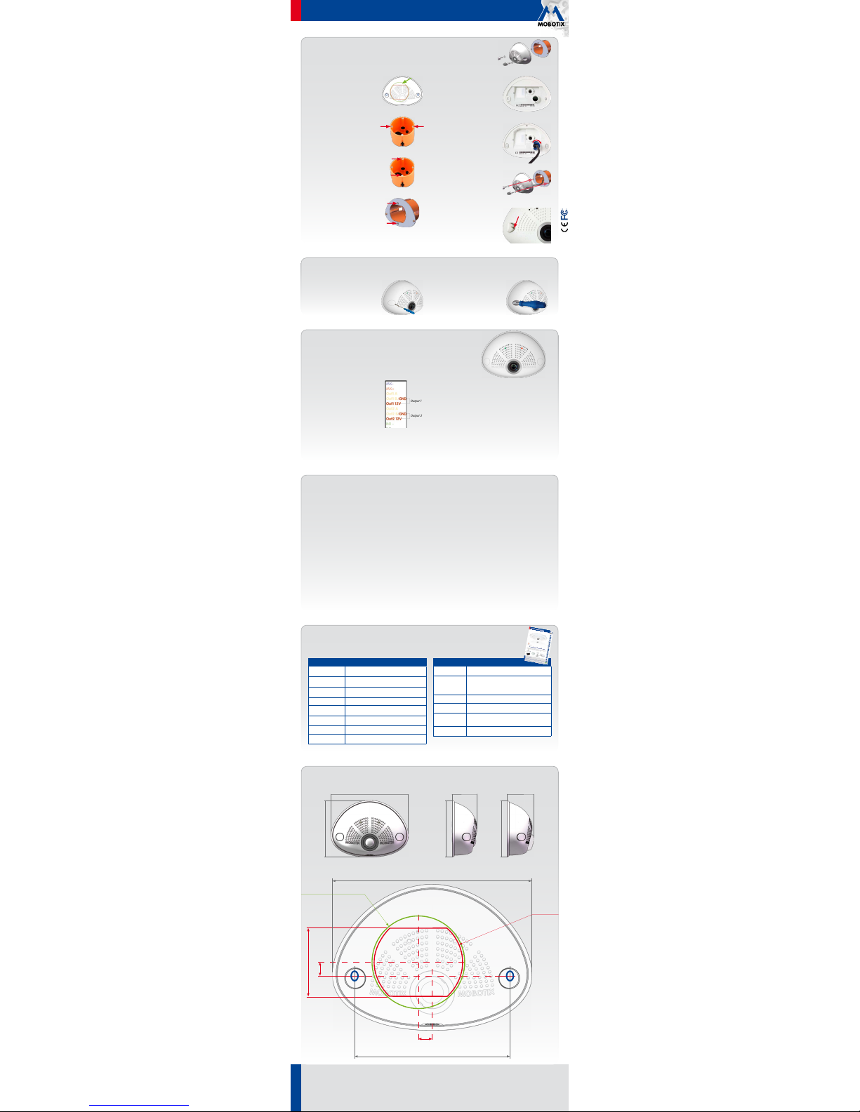
Dimensions/Drilling Template
145mm/5.71in
107mm/4.21in
50mm/1.97in
145mm/5.71in
Hole for cables
10mm/0.39in
Ø65mm/
2.56in
10mm/0.39in
113mm/4.45in
Ø68mm/
2.68in
C
a
v
i
t
y
w
a
l
l
s
o
c
k
e
t
45mm/1.77in
107mm/4.21in
i25 with lens B016
50mm/1.97in
107mm/4.21in
i25 with lens B036
Installation With Cavity Wall Installation Set (Accessory)
With this type of installation, the mounting plate of the Cavity Wall Installation Set is screwed onto a cavity wall socket.
The i25 itself is screwed onto the mounting plate using Allen screws. There is no drilling for dowels or screws required.
1.
Cut out the hole for the cavity wall socket
Mark the hole for the cavity wall socket
(green circle on drilling template) and cut
out the hole.
2. Insert the cavity wall socket
Insert the cavity wall socket and tighten the
two screws (red arrows) in order to fasten
the socket in the wall.
3. Remove the screws
Remove the two screws in the cavity wall
socket (red arrows), which are otherwise
used for fastening switches etc.
4. Attach the mounting plate
Use the two screws you just removed to
fasten the mounting plate onto the cavity
wall socket.
5. Press wall sealing on i25
Press the wall sealing onto the back of the
i25 and make sure that it lies flat all around
the rim. Note that the labels of the sealing
are pointing toward the back of the camera.
6. Connect the cables
Guide the cables of the camera from behind
through the cavity wall socket. Insert the Eth-
ernet cable and – if installed–the USB cable
into the corresponding sockets. Secure the
connectors using the blue bayonet catches.
7. Install the i25
Push the remaining cable into the cavity wall
socket, then press the camera and the wall
sealing onto the mounting plate. Use the
two Allen screws with the washers to fasten
the i25 onto the mounting plate (0.4Nm).
8. Apply screw plugs
Push in the screw plugs to close o the holes
with the screws. When doing so, make sure
that the notches in the plugs follow the guides.
Uninstalling the Camera
1. Remove the screw plugs
Remove the two white screw plugs using a
small flat-head screw driver, for example.
2. Remove the retaining screws
Remove the retaining screws using a suit-
able Allen wrench or screwdriver and take
o the entire camera.
Initial Operation of the i25
The initial operation starts with connecting the power supply (see section
«Network and Power Connec-
tion, Additional Cables»
in the
Q25 Camera Manual
). The first access follows the procedure described in
the same manual in the section «Initial Operation of the Camera». All other tasks require access to the
camera’s user interface in the browser. Enter the camera’s IP address into the address bar of the browser.
1.
Configuring and Using the MX-Bus-IO-Module
The camera will automatically detect an installed
MX-Bus-IO-Module (see Camera Status, System
section in browser).
The signal inputs can be used right away in the
signal input profiles
in the Setup Menu>Event
Overview. Likewise, the signal outputs can be
used in the
signal output profiles
in Admin
Menu> Hardware Configuration> Signal Out Profiles.
In addition, the signal inputs/outputs have been entered automatically
in the Admin Menu> Assign Wires dialog and can be used to control
doors and lights.
To use one or both signal outputs not as potential-free outputs (for relays),
but as
self-powered 12V outputs
, open the Admin Menu> Hardware
Configuration> Manage Hardware Expansions dialog. In the MxBus/
IO Board section, click on Connect for each output you want to use as
self-powered output.
2. Save the configuration
In the live image of the browser, select the Manage Settings quick control
and set Store Entire Configuration as value. The camera stores the con-
figuration in the permanent camera memory so that the settings will be
applied at the next camera reboot.