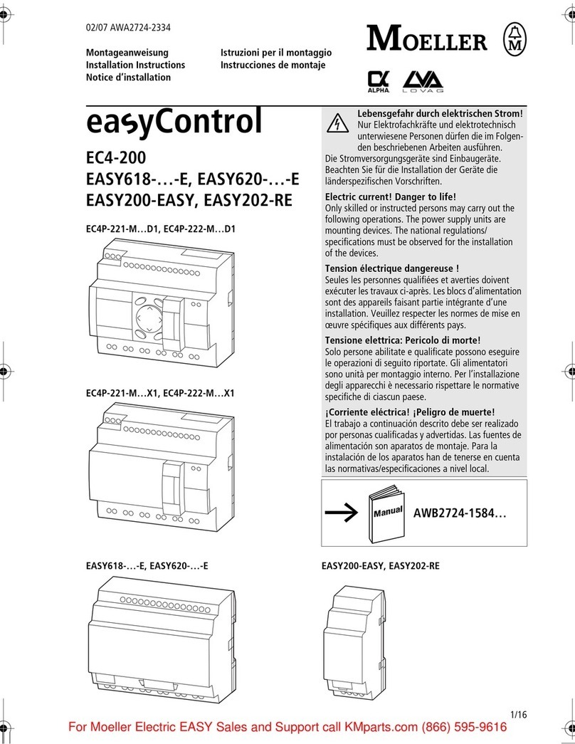
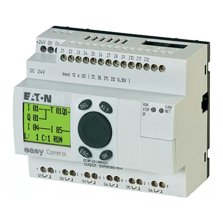
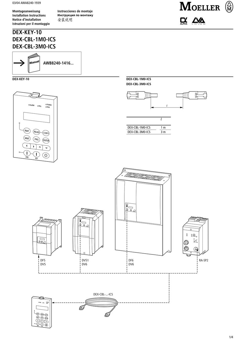
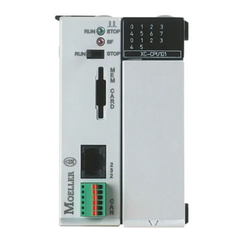
Moeller PS 4-300 Series User manual

Hardware and Engineering
PS 4-300
04/99 AWB 2700-1311 GB
1st published 1999, edition 07/99
© Moeller GmbH, Bonn
Author: Werner Albrecht
Editor: Thomas Kracht
Translators: Baker & Harrison, Terence Osborn
H1311U1g.fm Seite 1 Freitag, 4. Juni 1999 1:20 13

Caution!
Dangerous electrical voltage!
Before commencing the installation
●Disconnect the power supply of the
device.
●Ensure that the device cannot be
accidentally restarted.
●Verify isolation from the supply.
●Earth and short circuit.
●Cover or enclose neighbouring units that
are live.
●Follow the engineering instructions
(AWA) of the device concerned.
●Only suitably qualified personnel may
work on this device/system.
●Before installation and before touching
the device ensure that you are free of
electrostatic charge.
●Connecting cables and signal lines
should be installed so that inductive or
capacitive interference do not impair the
automation functions.
●Install automation devices and related
operating elements in such a way that
they are well protected against
unintentional operation.
●Suitable safety hardware and software
measures should be implemented for
the I/O interface so that a line or wire
breakage on the signal side does not
result in undefined states in the
automation devices.
●Ensure a reliable electrical isolation of
the low voltage for the 24 volt supply.
Only use power supply units complying
with IEC 60 364-4-41 or HD 384.4.41 S2.
●Deviations of the mains voltage from the
rated value must not exceed the
tolerance limits given in the
specifications, otherwise this may cause
malfunction and dangerous operation.
●Emergency stop devices complying with
IEC/EN 60 204-1 must be effective in all
operating modes of the automation
devices. Unlatching the emergency-stop
devices must not cause uncontrolled
operation or restart.
●Devices that are designed for mounting
in housings or control cabinets must only
be operated and controlled after they
have been installed with the housing
closed. Desktop or portable units must
only be operated and controlled in
enclosed housings.
●Measures should be taken to ensure the
proper restart of programs interrupted
after a voltage dip or failure. This should
not cause dangerous operating states
even for a short time. If necessary,
emergency-stop devices should be
implemented.
IBM is a registered trademark of International
Business Machines Corporation.
All other brand and product names are
trademarks or registered trademarks of the
owner concerned.
All rights reserved, including those of the
translation.
No part of this manual may be reproduced in
any form (printed, photocopy, microfilm or
any otherprocess) or processed, duplicated
or distributed by means of electronic
systems without written permission of
Moeller GmbH, Bonn.
Subject to alterations without notice.
1
04/99 AWB 2700-1311 GB
Contents
Contents 1
About This Manual 3
Documentation for the PS 4-300 3
Symbols 4
1 About The PS 4-300 Compact PLC 5
Hardware and software requirements 5
Features 5
Setup 6
Features of the PS 4-300 8
2 Engineering 15
EMC regulations 15
Connections 15
Programming device interface 18
Suconet K connector 19
Setting the bus terminating resistors 20
Local expansion module 21
Arrangement of the control cabinet 22
Power supply 24
Avoiding interference 30
3Mounting 35
Mounting on top-hat rail 35
Mounting on fixing feet 36
4 Topology Configuration 37
General 37
Configuring stations 38
Setting PS 4-300 parameters 42
Configuration example 54
5SlaveAddressing 61
Slaves without CPU 61
Slaves with CPU 63
H1311g.bk Seite 1 Freitag, 4. Juni 1999 1:12 13

2
04/99 AWB 2700-1311 GB
6Operation 65
Power-up behaviour 65
Shutdown behaviour 65
Operating states of the PLC 66
Start-up behaviour 69
Transferring programs 70
Starting the PLC with a memory module
plugged in 71
Programming via Suconet K 72
7 Test/Commissioning/Diagnostics 75
Status LEDs 75
Diagnostics 76
Message byte 80
Appendix 81
Accessories 81
Slave addressing 82
Technical data 85
Index 91
H1311g.bk Seite 2 Freitag, 4. Juni 1999 1:12 13

3
04/99 AWB 2700-1311 GB
About This Manual
Documentation for
the PS 4-300
The documentation for the PS 4-341-MM1 compact
PLC (referred to below as PS 4-300) is subdivided
into four manuals with the following topics:
Hardware and engineering
User interface for the programming software
Programming
Training guide
Hardware and engineering manual
The “Hardware and engineering” manual explains
how to install and configure the PLC and the settings
that can be made on the PLC.
How to configure and set the PLC parameters in the
topology configurator of the Sucosoft S 40
programming software is described in the “Software
configuration” chapter.
The “Slave addressing” chapter defines the general
syntax rules for addressing the stations in a
Suconet K network.
The “Tests/commissioning/diagnostics” chapter
provides an overview of the possible error and
diagnostic messages and their significance.
User interface for the programming software
manual
The PS 4-300 is programmed using version 3.0 or
higher of the Sucosoft S 40 programming software
(Windows, IEC 1131).
The user interface for the software is described in the
manual AWB 2700-1305 GB and in the
supplementary manual AWB 2700-1337 GB.
H1311g.bk Seite 3 Freitag, 4. Juni 1999 1:12 13

4
04/99 AWB 2700-1311 GB
Programming manual
Information on programming the PS 4-300 is
contained in the “Language elements
(Sucosoft S 40)” manual (AWB 2700-1306 GB).
Training guide
The Training guide AWB 27-1307 GB guide uses
practical examples to illustrate the key functions of
the Sucosoft S 40 software.
Symbols The symbols in this manual have the following
meaning:
왘Indicates handling instructions
Draws your attention to interesting tips and
additional information.
Warning!
Warns of the possibility of damage. The product,
anything in the immediate vicinity and data may
be damaged.
Caution!
Warns of the possibility of severe damage. The
product, anything in the immediate vicinity and
data may be severely damaged or totally
destroyed. There is also a risk of injury or even
death.
H1311g.bk Seite 4 Freitag, 4. Juni 1999 1:12 13

5
04/99 AWB 2700-1311 GB
1 About The PS 4-300 Compact PLC
Hardware and software
requirements
To program the PS 4-300 you need:
A PC (IBM or IBM-compatible) with
Pentium processor
Windows 95, Windows 98 or Windows NT 4.01
operating system
16 MB RAM (32 MB recommended)
3.5” disk drive/ 1.44 MByte and CD-ROM drive
Hard disk with at least 50 MB free space; a
temporary directory called C:\{_PS 4_}.TMP is
created and then deleted again during
installation. This requires at least 250 KB free on
drive C:
Serial COM port
Parallel printer port (LPT)
VGA graphics card
ZB 4-303 KB1 programming cable (connecting
cable between the PC and PS 4-300)
Features The main features of the PS 4-300 are as follows:
24 V DC power supply
16 digital inputs 24 V DC (some are multi-function
inputs for “high-speed counters”, incremental
encoders and for use as alarm inputs.
14 digital outputs 24 V DC
2 analog inputs
1 analog output
1) (die Version 3.x Sucosoft version 3.x is the last version
supported by Windows 3.1x
H1311g.bk Seite 5 Freitag, 4. Juni 1999 1:12 13

About The PS 4-300
Compact PLC
6
04/99 AWB 2700-1311 GB
Setup Figure 1 contains an overview of the controls, LEDs
and device connections on the PLC.
Warning!
Always ground yourself before touching the PLC
to protect the components against electrostatic
discharge.
Key to Figure 1:
햲24 V DC power supply
햳Incremental encoder/“high-speed counter” input
햴16 digital inputs 24 V DC
햵Plug-in screw terminal
햶Status LEDs for digital inputs
햷2 alarm inputs
햸24 V DC power supply for outputs
햹14 digital outputs 24 V DC/0.5 A; short-circuit and overload-proof
햺Status LEDs for digital outputs
햻2 analog inputs U0, U1(0 to 10 V)
1 analog output U10 (0 to 10 V)
햽Suconet K interface
햾Setpoint potentiometers P1, P2
햿Switch S1 for bus terminating resistors
헀Programming device interface (PRG)
헁Memory module
헂Status LEDs for PLC
H1311g.bk Seite 6 Freitag, 4. Juni 1999 1:12 13

Setup
7
04/99 AWB 2700-1311 GB
.0. .2.3.4 .5 .6.7
0
.. . . . .
0V
1
햴햶
햵
햵
햺햹햺
햵
햹
햶
햵
햴
햷
헂
헁
헀햿 햾 햽
햳
햲
1234
0VV42 Power Supply
ttery
4 Ba yRead3 Not
n2 Ruady1 Re
Suconet K
PRG
12
S1 P2P1
Output
Digital
Input
Digital
5
4
3
2
1
0
0
10
U
1
U
0
U
Input/Output
Analog Output
Digital
Input
Digital
7.6.5.4.3.2.1.0.
1
PS4-341-MM1
Power Supply
Output
V
247.6.5.4.3.2.
1
.
0.
1
햸
햻
I
0V
I
0V
A
0V
Q
Figure 1: Setup of the PS 4-300
H1311g.bk Seite 7 Freitag, 4. Juni 1999 1:12 13

About The PS 4-300
Compact PLC
8
04/99 AWB 2700-1311 GB
Features of the
PS 4-300
햲Power supply unit
The PS 4-300 is operated with a rated voltage of
24 V DC. The power supply connection is protected
against polarity reversal. The 24 V connection
enables the PLC to be supplied with voltages to
industrial standards (IEC) and is electrically isolated
from the CPU.
햳Multi-function inputs
Inputs I0.0, I0.1, I0.2 and I0.3 are used to connect an
incremental encoder. The connection assignment is
shown in Figure 12. Any 24 V encoder (without
antivalent signals) may be connected. The
“IncEncoder”1function block is available for
processing input signals.
Input I 0.0 (“high-speed counter”) can also be used to
record high-speed pulse trains. The signal level (L/H)
at input I0.1 determines the counting direction. This
input is supported by the “CounterAlarm”1 function
block.
Inputs I0.0 to I0.3 can also be used as digital inputs.
햴Digital inputs
The PLC has 16 digital inputs. They are electrically isolated
from the CPU and are designed for a rated voltage of 24 V
DC. The typical input delay of 100 s (not including the
multi-function inputs) ensures short response times, e.g.
for directly scanning peripheral devices or evaluating
alarms. Inputs I0.0 to I0.7 and I1.0 to I1.7 can be addressed
in bit, byte or word format with I/O commands.
1) These function blocks are described in chapter 6 of the
manual “Language Elements for the PS 4-150/-200/-300
and PS 416” (AWB 2700-1306 GB).
H1311g.bk Seite 8 Freitag, 4. Juni 1999 1:12 13

Features of the PS 4-300
9
04/99 AWB 2700-1311 GB
햵Plug-in screw terminals
An overview of the digital and analog I/O connections
is given in the “Engineering” chapter.
햶 Status LEDs for digital inputs
The physical and logical states of the PLC’s signal
inputs and diagnostic status word are indicated by
light-emitting diodes (LEDs) (See "Diagnostic status
word" on page 76).
햷 Alarm inputs (interrupt input)
Inputs I1.0 and I1.1 enable you to respond quickly to
events regardless of the cycle time. In the Sucosoft
S40 programming software, the alarm inputs are
supported by the “EdgeAlarm”1, function block. The
rising or falling edge can also be used to evaluate
such events
햹 Digital outputs
The PS 4-300 has 14 digital outputs 24 V DC. They
can withstand a load of 0.5 A and have a 100 % duty
factor. They are electrically isolated from the CPU
and are short-circuit and overload-proof. Up to four
outputs may be connected in parallel, ideally in
groups (Q0.0 to Q0.3, Q0.4 to Q0.5, Q1.0 to Q1.3 and
Q1.4 to Q1.7).
The outputs can be addressed in bit, byte or word
format with I/O commands. Check the composition
of the groups if the outputs are connected in parallel.
1) These function blocks are described in chapter 6 of the
manual “Language Elements for the PS 4-150/-200/-300
and PS 416” (AWB 2700-1306 GB).
H1311g.bk Seite 9 Freitag, 4. Juni 1999 1:12 13

About The PS 4-300
Compact PLC
10
04/99 AWB 2700-1311 GB
햺 Status LEDs for digital outputs
The logical states of the digital outputs are indicated
by light-emitting diodes (LEDs).
햻 Analog inputs and outputs
The PLC has two analog inputs U0and U1. The signal
range is 0 to +10 V and the resolution is 10 bits
(1024 increments).
The PLC has one analog output U10 with a signal
range of 0 to +10 V and a resolution of 12 bits
(4096 increments).
The analog inputs and outputs are addressed as
follows:
U0: IAW0.0.0.4
U1: IAW0.0.0.6
U10: QAW0.0.0.0
The analog inputs and outputs are not electrically
isolated from the CPU.
햽 Suconet K connector
This interface performs the following functions:
It is the network interface for Suconet K stations,
such as Suconet K master or slave PLCs or
EM 4-... expansion modules.
It is used to exchange data with peripherals
equipped with a serial interface (e.g. printer,
terminals, etc.). This type of communication is
used for process data acquisition, visualisation
etc., but should not be used to exchange data for
process control.
Network programming via Suconet K is described
under "Programming via Suconet K" on page 72.
The Suconet K connector (RS 485) is electrically
isolated from the CPU.
H1311g.bk Seite 10 Freitag, 4. Juni 1999 1:12 13

Features of the PS 4-300
11
04/99 AWB 2700-1311 GB
The Sucom A protocol enables markers and
status and diagnostic bits on the PLC to be
accessed directly. It provides read and write
access to the marker range, whereas only read
access to the status and diagnostic bits is
possible.
Sucom A access can be provided via the PRG
and SBI interfaces. Sucosoft S 40 contains a
function block called “SUCOM-A”1for this
purpose.
햾 Setpoint potentiometers
The two setpoint potentiometers P1and P2 can be
set externally using a screwdriver. In other words,
setpoints can be changed without the use of a
programming device. The resolution is 10 bits. In the
programming software, the setpoint potentiometers
are addressed using the operands “IAW0.0.0.0” and
“IAW0.0.0.2”.
햿 Switch S1 for setting the bus terminating
resistors
The bus terminating resistors at the first and last
physical stations on the bus must be switched on,
whereas all the other stations must be switched off
(see "Setting the bus terminating resistors" on
page 20).
1) These function blocks are described in chapter 6 of the
manual “Language Elements for the PS 4-150/-200/-300
and PS 416” (AWB 2700-1306 GB).
H1311g.bk Seite 11 Freitag, 4. Juni 1999 1:12 13

About The PS 4-300
Compact PLC
12
04/99 AWB 2700-1311 GB
헀Programming device interface (PRG)
The interface performs the following functions:
Programming the PLC via the PC
It is used to exchange data with peripherals
equipped with a serial interface (e.g. printer,
terminals, etc.). This type of communication is
used for process data acquisition, visualisation
etc., but should not be used to exchange data for
process control.
Communication via the PRG interface (RS 232/485)
is controlled by the “SCO”1function block in
Sucosoft S 40. The interface is electrically isolated
from the CPU.
헁 Memory and memory module
The PS 4-300 has an internal battery-backed RAM
which is subdivided into a user program memory and
a data memory. Up to 0.5 MB is available for the user
program and as the data memory. Memory allocation
is dynamic. The capacity of the internal RAM cannot
be upgraded using plug-in memory modules. The
ZB 4-901-SF1 memory module acts as the backup
memory.
헂 Status LEDs for the PLC
The PLC’s states are indicated by four light-emitting
diodes: “Ready”, “Run”, “Not Ready” and “Battery”.
The meaning of these LEDs is described under
"Status LEDs" on page 75.
1) These function blocks are described in chapter 6 of the
manual “Language Elements for the PS 4-150/-200/-300
and PS 416” (AWB 2700-1306 GB).
H1311g.bk Seite 12 Freitag, 4. Juni 1999 1:12 13

Features of the PS 4-300
13
04/99 AWB 2700-1311 GB
Figure 2: Controls and LEDs on the PS 4-300 (with the
housing flap open)
햲Back-up battery
햳Reset button
햴Plug connector for local expansion modules
햵Operating mode selector switch
햲Backup battery
The battery backs up the internal RAM and the real-
time clock.
햲
+
Battery
Reset3 Run M-
2 Run
1 Halt
Reset
S2
32
1
햵
햳
햴
Warning!
The power supply must be switched on when you
replace the back-up battery, otherwise programs
and data will be lost.
H1311g.bk Seite 13 Freitag, 4. Juni 1999 1:12 13

14
04/99 AWB 2700-1311 GB
햳, 햵 Operating mode selector switch/reset
button
The operating mode selector switch is used to select
the “Halt” (stop), “Run” and “Run M reset” operating
modes. The operating states are described in detail
under "Operating states of the PLC" on page 66.
햴Plug connector for the local expansion module
The plug connector acts as the interface for
connecting local expansion modules (LE 4-...).
Real-time clock
The PLC is equipped with a battery-backed real-time
clock which enables machines and equipment to be
switched at set times. The programming software
provides a function block for addressing and
scanning the real-time clock. This function block can
also be used to switch between summer and winter
time (daylight savings time).
H1311g.bk Seite 14 Freitag, 4. Juni 1999 1:12 13

15
04/99 AWB 2700-1311 GB
2 Engineering
EMC regulations Observe the engineering instructions in the manual
“EMC Engineering Guidelines for Automation
Systems” (AWB 27-1287 GB).
Connections 왘Screened data and signal cables
Route screened data and signal cables on the left
and the right of the device along the shortest
possible distance and connect the screen braid
to the ground terminal using a low-impedance
connections and large contact areas
(See Figure 3, item 햲).
왘Connect the screen braid with the metal sleeve of
the plug connector (DIN plugs) 햴.
왘Insulate the end of the screen braid as close as
possible to the signal cable entry 햳.
H1311g.bk Seite 15 Freitag, 4. Juni 1999 1:12 13

Engineering
16
04/99 AWB 2700-1311 GB
Figure 3: Grounding the screens of the cables
햳
햴
M 44/EPS
0 V
V24
M4
햲
H1311g.bk Seite 16 Freitag, 4. Juni 1999 1:12 13

Connections
17
04/99 AWB 2700-1311 GB
Overview
Figure 4: Overview of the connections
햲Screw terminals: 24 V DC power supply
Connector cross-sections:
flexible with ferrule 0.22 to 2.5 mm2 (AWG 23 ... 13)
solid 0.22 to 2.5 mm2(AWG 23 ... 13)
햳Plug-in screw terminals
햴Conductor cross-sections:
flexible with ferrule 0.22 to 1.5 mm2 (AWG 23 ... 16)
solid 0.22 to 2.5 mm2 (AWG 23 ... 13)
햵Plug connector for local expansion modules (LE 4)
햶Suconet K interface (RS 485)
햷Programming device interface (RS 232)
Suconet K
12
Power Supply
PRG
햳
햴
햳
햴
햳
햴
햲
햶
햷
햳
햴
+
햵
H1311g.bk Seite 17 Freitag, 4. Juni 1999 1:12 13

Engineering
18
04/99 AWB 2700-1311 GB
Programming device
interface
Pin assignment
Figure 5: Pin assignment on the programming device
(PRG) interface (left-hand socket, top view)
PIN 1 Not used
PIN 2 RxD
PIN 3 0 V for interface
PIN 4 Not used
PIN 5 TxD
PIN 6 – 8 Not used
Connecting the programming device (PC)
왘Connect the PC to the PRG interface (left-hand
socket) of the PS 4-300 using the ZB 4-303 KB1
programming cable:
Figure 6: Pin assignment of the ZB 4-303 KB1
programming cable
3
5
2
4
16
78
1
2
3
6
7
3
5
2
4
1
6
78
9
5
4
8
PC-Schnittstelle
COM
(9pol. DIN-Buchse)
PRG-Schnittstelle
PS 4-341-MM1
(8pol. DIN-Stifte)
Brücken
H1311g.bk Seite 18 Freitag, 4. Juni 1999 1:12 13
This manual suits for next models
1
Table of contents
Other Moeller Controllers manuals

Moeller
Moeller DEX-KEY-10 User manual

Moeller
Moeller XStart User manual

Moeller
Moeller ps4-201-mm1 User manual

Moeller
Moeller Home-Manager User manual

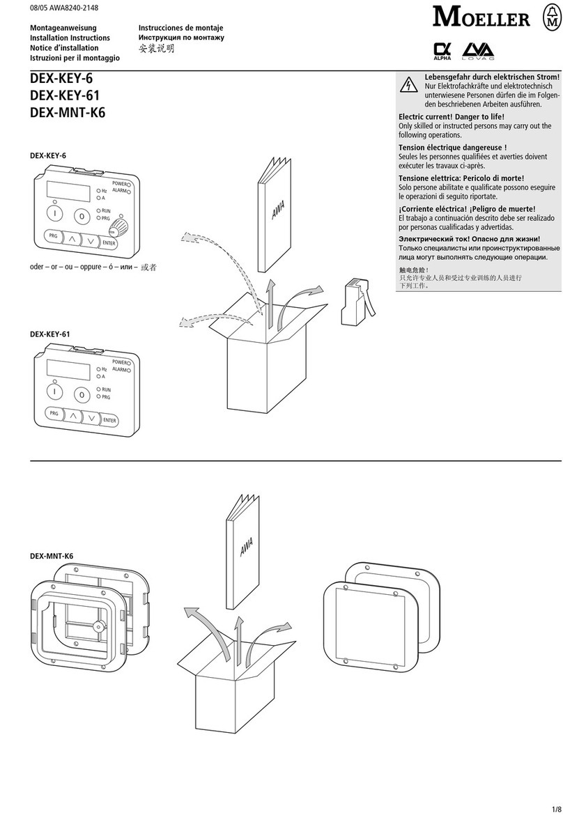
Moeller
Moeller DEX-KEY-6 User manual

Moeller
Moeller easyControl EC4-200 Parts list manual

Moeller
Moeller PS 4-271-MM1 User manual

Moeller
Moeller RMQ 22 User manual

Moeller
Moeller Xcomfort CAAE-01/01 User manual

Moeller
Moeller NZM2-XRD Series Service manual