manuals.online logo
Brands
  1. Home
  2. •
  3. Brands
  4. •
  5. Salus
  6. •
  7. Controllers
  8. •
  9. Salus PC16F User manual

Salus PC16F User manual

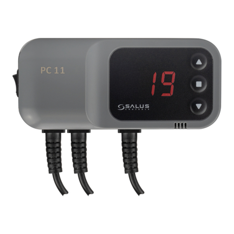
Model PC16F
PL Sterownik do pompy i wentylatora.
ENG Pump and fan controller.
RUS    
RO Controle pentru pompa de reciruclare si ventilatorul cazanului
PL
SALUS PC16F
Zasada działania
Sterownik PC16F 

             
ustawienie temperatury              
sterownika w menu (F).
chawy)
Funkcja F2 drewno (moc dmuchawy 20% + przedmuchy)



W funkcjach od F1 do F4            
            

Wy

Funkcja F5           

Obsługa sterownika
   
 
             
przycisk . . F nas
interesuje klawiszami 
W przypadku funkcji F5 

C -
D -moc wentylatora
1-czas przedmuchu
2-przerwa przedmuchu
3-temperatura wygasania
4 -czas rozpalania
 


alarm - 
anty-stop - 
anty-zamarzanie - 
Blokada Dmuchawy i start pracy dmuchawy:
isk do F (menu w tym czasie nie

Załączenie pompy C.O. do pracy ciągłej:
 
e przytrzyma klawisz  
Opcje serwisowe
 
 .
d- to typ dmuchawy:
1- DMUCHAWA WPA120
2- DMUCHAWA DP-01, DP-02
3- DMUCHAWA RV-14
4- DMUCHAWA DP-120
F1 - maksymalna moc dmuchawy podczas rozpalania tylko dla funkcji F1 w menu.
Po ustawieniu typu i mocy dmuchawy, sterownik automatycznie przejdzie do pracy na zadanych w opcjach
serwisowych parametrach, po 5 sekundach.
Sposób montażu
uprawnienia elektryczne!
Czujnik              

Przewód zasilający 
- 230V,
-zielony (ochronny) - 
UWAGA: Pojawienie się na wyświetlaczu komunikatu „99” oznacza awarię czujnika temperatury.
ENG
SALUS PC16F
Principle of operation
The PC16F controller controls the pump for the central heating and fan. It is designed for the control of solid fuel boilers,
wood, coal and Culm. You can choose from five versions of the controller modes conditioned by the type of fuel and the
type of boiler. As first step which you must do before starting to use the driver is to set the system temperature in normal
mode of boiler operation and select fuel operation mode of the controller in the menu (F).
F1 - wood and coal (smooth power of the fan).
F2 - wood (fan power 20% + scavenge).
F3 coal (fan power 50% + scavenge).
The F4 culm (fan power 100% + scavenge).
The F5 individual settings.
The functions F1 to F4, the controller automatically sets the fan power, activation of the pump for central heating and the
boiler extinction temperature by smart control algorithm. When function F1 is set the fan power is reduced when the
temperature is close to the set by user boiler temperature.
Extinction of the boiler is in the range from 

The F5 function allows you to set individual adjustment of all parameters of the controller like: pump activation
temperature, fan power interruptions and duration of scavenge, inflame, and period of extinction.
Handling
After turn on power controller automatically switches to inflame mode. Enter to menu by pressing on the controller. The
display shows the set temperature flashing, you have the ability to set the desired temperature by keep pressing .
Once the desired temperature is set, press the button again. The display shows the F and actual mode number. You can
select the desire mode by keys. After selecting the desired function the driver returns to the work itself.
For F5 function settings please press key.
You will be able to set below options:
C - start temperature of central heating pump
D - fan power
1 -scavenge time
2 - scavenge break
3 - temperature extinction
4 - inflame time
Enter to the menu by pressing the key, and set the desire value by pressing the keys .
After setting the desired values, the driver will remember it and after a few seconds will return to normal work mode.
The controller is also equipped with the following features:
- 
-stop - prevents the sticking of the pump out of the heating season, running it every 14 days for 15 seconds,
-freeze - 
Fan lock and start of the fan:
To lock the fan press 
this time is not available). To unlock, press the button again.
Central heating pump continuous operation:
To set the pump for the constant work press for 3 seconds. The pump will work constantly until you hold the button
again or turn OFF the power on the main switch.
Service options
In the service options you can change the type of fan and the power of the fan during inflame. Enter into service options is
possible after the power is turned off and turned on again while holding down the keys
Type of fan:
1 - FAN WPA120
2 - FAN DP-01, DP-02
3 - FAN RV-14
4 - FAN DP-120
F1 - the maximum power of the blower while inflame is only possible only for F1 mode.
After setting the type and power of the fan, the controller will automatically go back to work on the selected service
parameters, after 5 seconds.
Mounting

ernal factors with duct
tape (it cannot be immersed in any liquid).

- blue and brown 230V,
- yellow-green (protective) - should be connected to ground
NOTE: If you see “99” on the LCD display – temperature sensor is broken.
RUS
SALUS PC16F
Общие принципы работы
PC16F  
            
  
             
(F).





              
         
           

                  

 
           

ОБСЛУЖИВАНИЕ РЕГУЛЯТОРА
           
             
   
 F
   

  

CC.O.
D
1- 
2- 
3- 
4- 
  .



сигнализация - 
анти-стоп - 

системой предупреждающей замерзание - 

Блокировка воздуходувки и включение воздуходувки
 до F 
  .
Включение насоса C.O. в режим постоянной работы

  

Варианты обслуживания


 
d 
1 
2 -01, DP-02
3 -14
4 -120
F1 

-
Способ установки
разрешениями на работу с
электроприборами!
Датчик 

Провод питающий 
 - 230V,
- 
Если вы видите "99" на ЖК-дисплее - датчик температуры не работает
RO
SALUS PC16F
Principii de functionare
Controlerul CS20 comanda pompa de incalzire centrala si ventilatorul. Se poate utiliza pentru cazane pe combustibil solid,
lemn, carbune si culm (praf de carbune). Puteti alege din 5 tipuri de comanda, in functie de combustibilul folosit si tipul
boilerului. Primul pas, inainte de folosirea controlerului este setarea furnalului, asta pentru a mentine controlul in timpul
functionarii boilerului, dupa care selectati functia dorita in meniul controlerului (F).
F1 lemn si carbune (putere mica a ventilatorului)
F2 lemn (puterea ventilatorului la 20% + suflare)
F3 carbune (puterea ventilatorului la 50% + suflare)
F4 puterea ventilatorului la 100% + suflare
F5 setari preferentiale utilizator
La functiile, de la F1 la F4, controlerul seteaza automat, printr-un algoritm propriu, puterea ventilatorului, activarea pompei
de incalzire centrale si temperatura de ardere.
La activarea functiei F1 puterea ventilatorul se reduce automat cand temperatura este apropiata de cea setata.


Functia F5 permite setarea manuala a tuturor parametriilor: temperatura de activare a pompei, puterea ventilatorului,
intreruperea si durata suflarii, aprinderea si perioada de stingere.
Instructiuni de folosire a controlerului
Dupa pornirea controlerului modul de aprindere se initializeaza automat, intrati in meniu si apasati aflat pe controler.
Afisajul arata temperatura intermitent, acum aveti posibilitatea de a schimba temperatura cu ajutorul butonului butonul
Dupa setarea temperaturii apasati din nou butonul .Pe afisaj va aparea F si numarul functiei. Puteti selecta functia
dorita cu ajutorul butonului
Dupa selectarea functiei, termostatulu revine la modul normal de lucru.
Pentru a selecta functia F5 apasati butonul
Veti putea selecta optiunile:
C temperatura de pornire a pompei de recirculare
D puterea ventilatorului
1 -timpul de suflare
2 pauza de suflare
3 temperatura de stingere a cazanului
4 timpul de ardere
Intrati in meniul prin apasarea butonul , si inserati valoarea dorita prin apasarea butonului
Dupa setarea valorilor dorite, termostatul va reveni la modul normal de lucru.
Alte functii:
 
-stop - la fiecare 15 zile, termostatul comanda pornirea pompei timp de 15 sec,
 -freeze -             
pompei.
Fan lock and start of the fan:
Blocarea ventilatorului:
Pentru a bloca ventilatorul apasati butonul Pe afisa  
Pentru a debloca ventilatorul aparati din nou butonul
Comanda continua a pompei de incalzire centrala:
Pentru a porni pompa in comanda continuua apasati si tineti apasat tinp de 3 secunde butonul In acest mod pompa va
functiona continuu, iar pentru a reveni la modul normal de lucru repetati comanda anterioara sau inchideti si deschideti
controlerul.
Optiuni service
In optiunea service puteti schimba tipul ventilatorului si puterea acestuia in timpul arderii. Pentru a intra in modul service va
trebui sa opriti controlerul si sa-l reporniti tinand apasat butonul
Tipuri de ventilator:
1 - WPA120
2 - DP-01, DP-02
3 - RV-14
4 - DP-120
F1 puterea maxima al ventilatorului se poate selecta doar pentru functia F1.
In cazul in care, timp de 5 secunde, nu se mai apasa nici un alt buton, setarile facute vor fi memorate, iar controlerul va
reveni la modul normal de lucru.
Montarea controlerului
Montarea controlerului trebuie facuta de catre o persoana autorizata! Senzorul trebuie montat la iesirea din boiler cu
ajutorul clemei de prindere si izolata de factori exteriori cu ajutorul bandei izolatoare (senzorul nu este imersibil in lichide).
Cablul de alimentare al pompei trebuie conectat astfel:
albastru si maro 230 V
galben-verde - impamantare
Dacă vedeți "99" pe ecranul LCD - senzor de temperatură este rupt
PRZYCISKI/BUTTONS
SCHEMAT PODŁĄCZENIA / WIRING DIAGRAMS
1.

7.

Power supply indicator
Sound alarm


Indicator termostat pornit

2.

8.

Indicator C.H. pump operation
Display


Indicator 

3.

9.
Czujnik C.O.
Indicator ventilator operation
Sensor C.H.



Senzor pompa de recirculare
4.
Klawisz plus
10.
Termik
Plus key
Thermistor


Buton +
Termistor
5.
Klawisz menu
11.
Zasilanie wentylatora
Menu key
Power supply ventilator


Buton meniu
Alimentare ventilator
6.
Klawisz minus
12.
Zasilanie pompy C.O.
Minus key
Power supply C.H. pump


Buton -
Alimentare pompa de recirculare
13.
Zasilanie 230V
Power supply 230V

Alimentare termostat - 230V
Salus Controls Romania SRL
Strada Traian Vuia 126
Cluj-Napoca
Tel: 0364 435 696
Email: [email protected]

Other Salus Controllers manuals

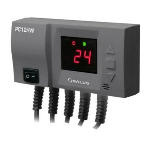
Salus PC12HW User manual

Salus

Salus PC12HW User manual

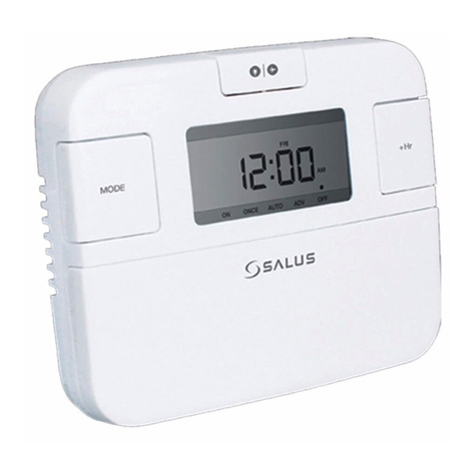
Salus RX10RF User manual

Salus

Salus RX10RF User manual

Salus PC11W User manual

Salus

Salus PC11W User manual

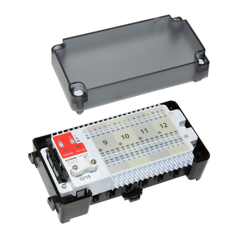
Salus KL04NSB User manual

Salus

Salus KL04NSB User manual

Salus TRV10RFM User manual

Salus

Salus TRV10RFM User manual

Salus AKL04P User manual

Salus

Salus AKL04P User manual

Salus TRV10RFM-3 User manual

Salus

Salus TRV10RFM-3 User manual

Salus TRV10RFM User manual

Salus

Salus TRV10RFM User manual

Salus EP110 User manual

Salus

Salus EP110 User manual

Salus PCSol 150 User manual

Salus

Salus PCSol 150 User manual

Salus SC102ZB User manual

Salus

Salus SC102ZB User manual

Salus PCSol 300 User manual

Salus

Salus PCSol 300 User manual

Salus EP210 User manual

Salus

Salus EP210 User manual

Salus WT100 Specification sheet

Salus

Salus WT100 Specification sheet

Salus AKL06P User manual

Salus

Salus AKL06P User manual

Salus THB23030 User manual

Salus

Salus THB23030 User manual

Salus THB23030 User manual

Salus

Salus THB23030 User manual

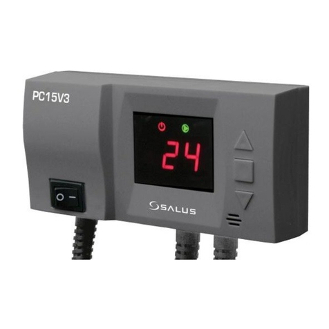
Salus PC15V3 User manual

Salus

Salus PC15V3 User manual

Salus RX10RF User manual

Salus

Salus RX10RF User manual

Salus AH2430 User manual

Salus

Salus AH2430 User manual

Salus PC11W User manual

Salus

Salus PC11W User manual

Salus PC12HW User manual

Salus

Salus PC12HW User manual

Salus EP310 User manual

Salus

Salus EP310 User manual

Salus TRV10RFM User manual

Salus

Salus TRV10RFM User manual

Popular Controllers manuals by other brands

Regin RVAZ4-24 Instruction

Regin

Regin RVAZ4-24 Instruction

FW Murphy TTD Series How to replace

FW Murphy

FW Murphy TTD Series How to replace

Lexicon DC-1 quick reference

Lexicon

Lexicon DC-1 quick reference

Mitsubishi Electric MELSEC iQ-F FX5 user manual

Mitsubishi Electric

Mitsubishi Electric MELSEC iQ-F FX5 user manual

Skyrc TORO 8 X150 instruction manual

Skyrc

Skyrc TORO 8 X150 instruction manual

Bose SoundTouch quick start guide

Bose

Bose SoundTouch quick start guide

Filtration Group MFS-05 Translation of the original instructions

Filtration Group

Filtration Group MFS-05 Translation of the original instructions

Rohm BD GA5 Series Application Information

Rohm

Rohm BD GA5 Series Application Information

Allen-Bradley PLC-3 Series quick start

Allen-Bradley

Allen-Bradley PLC-3 Series quick start

SOLAR controls WATTrouter ECO user manual

SOLAR controls

SOLAR controls WATTrouter ECO user manual

Trane Tracer UC400 installation guide

Trane

Trane Tracer UC400 installation guide

MERRICK MC3 Hardware manual

MERRICK

MERRICK MC3 Hardware manual

TECH ST-21D5 user manual

TECH

TECH ST-21D5 user manual

Pentek Pressure Central PPC20-1A-6A0-4 owner's manual

Pentek

Pentek Pressure Central PPC20-1A-6A0-4 owner's manual

MSR INTEC PolyGard 2 MGC6 user manual

MSR

MSR INTEC PolyGard 2 MGC6 user manual

Mitsubishi MELSEC-QnA Series user manual

Mitsubishi

Mitsubishi MELSEC-QnA Series user manual

Mitsubishi Electric NZ2GF2S-60IOLD8 user manual

Mitsubishi Electric

Mitsubishi Electric NZ2GF2S-60IOLD8 user manual

Cervis MCB Series user manual

Cervis

Cervis MCB Series user manual

manuals.online logo
manuals.online logoBrands
  • About & Mission
  • Contact us
  • Privacy Policy
  • Terms and Conditions

Copyright 2025 Manuals.Online. All Rights Reserved.