Moffat TURBOFAN P12M Series User manual

234277-2
Installation and Operation Manual
P8M / P12M Series
Proofer/Holding Cabinets
(Manual Operation)
P
SERIES

The reproduction or copying of any part of this manual by any means whatsoever is strictly forbidden unless authorized previously in writing
by the manufacturer.
In line with policy to continually develop and improve its products, Moffat Ltd. reserves the right to change the specifications and design
without prior notice.
© Copyright Moffat Ltd. June 2010.
MANUFACTURED BY
Moffat Limited
Christchurch
New Zealand
INTERNATIONAL CONTACTS
AUSTRALIA
Moffat Pty Limited
E.Mail: [email protected]
Main Office: (tel) (03) 9518 3888
(fax) (03 9518 3833
Service: (tel): 1800 622 216
Spares: (tel): 1800 337 963
Customer Service: (tel): 1800 335 315
(fax): 1800 350 281
CANADA
Serve Canada
Web: www.servecanada.com
E.Mail: [email protected]
Sales: (tel): 800 551 8795 (Toll Free)
Service: (tel): 800 263 1455 (Toll Free)
NEW ZEALAND
Moffat Limited
Web: www.moffat.co.nz
E.Mail: [email protected]
Main Office: (tel): 0800 663328
UNITED KINGDOM
Blue Seal
Web: www.blue-seal.co.uk
E.Mail: [email protected]
Sales: (tel): 0121 327 5575
(fax): 0121 327 9711
Spares: (tel): 0121 322 6640
(fax): 0121 327 9201
Service: (tel): 0121 322 6644
(fax): 0121 327 6257
UNITED STATES
Moffat
Web: www.moffat.com
Sales: (tel): 800 551 8795 (Toll Free)
(tel): 336 661 1556
(fax): 336 661 9546
Service: (tel): 800 858 4477 (Toll Free)
(tel): 366 661 1556
(fax): 336 661 1660
REST OF WORLD
Moffat Limited
Web: www.moffat.co.nz
E.Mail: [email protected]

Contents List
P8M / P12M Turbofan Proofer / Holding Cabinets.
Model Numbers Covered in this Manual
P8M - Turbofan Proofer / Holding Cabinet - 8 Tray.
P12M - Turbofan Proofer / Holding Cabinet - 12 Tray.
Introduction ........................................................................................................... 2
Safety Information
Specifications......................................................................................................... 3
Installation............................................................................................................. 4
Installation Requirements
Unpacking
Location
Clearances
Electrical Connection
Water Connection
Operation ............................................................................................................... 6
Operation Guide
Proofer / Holding Cabinet Control Panel
Description of Controls
Operating in ‘Proof’ Mode
Operating in ‘Hold’ Mode
Cleaning ................................................................................................................. 8
Cleaning Guidelines
Proofer / Holding Cabinet Cleaning
Fault Finding ........................................................................................................ 11
Electrical Schematic............................................................................................. 12
Replacement Parts List ........................................................................................ 13

Introduction
2
Before using your new Proofer / Holding Cabinet, please
read this instruction manual carefully, pay particular
attention to any information labelled ‘WARNING’,
‘CAUTION’, ‘IMPORTANT’ or ‘NOTE’ in this manual.
Indicates a hazardous situation
which, if not avoided, will result in
death or serious injury.
Indicates a hazardous situation
which, if not avoided, will result in
minor or moderate injury.
If you are unsure of any aspect of the installation,
instructions or performance of your Proofer / Holding
Cabinet, contact your TURBOFAN dealer promptly. In
many cases a phone call could answer your question.
Should you contact your TURBOFAN dealer on any matter
concerning this proofer / holding cabinet, please have the
information provided opposite, readily available.
Caution
Warning
Model Number:
Serial Number:
Dealer:
Service Provider:
Date Installed:
Date Purchased:
This manual must be kept by the owner for future
reference.
A record of the
Date of Purchase,
Date of Installation
and
Serial Number of the Proofer / Holding Cabinet
should be recorded in the area provided below.
The serial number of this Proofer / Holding Cabinet
can be found on the Technical Data Plate located on
the front right hand side panel, see diagram in
‘Installation Section’
.
Safety Information
For your safety, please pay attention to the following symbols
marked on the appliance.
- Risk of electric shock.
No user serviceable parts inside.
Qualified service person access only.
Disconnect from power before servicing.

Specifications
3
P8M / P12M Specifications Tables:-
P8M Proofer / Holding Cabinet P12M Proofer / Holding Cabinet
Power Ratings
Tray Details
Tray Capacity Tray Spacing
P8M
110-120V, 1P+N+E, 60HZ, 1.45 kW
220-240V, 1P+N+E, 50/60HZ, 1.50 kW 8 x US Full Pan
8 x EN 600 x 400 mm tray 76 mm / 3”
P12M
110-120V, 1P+N+E, 60HZ, 1.95 kW
220-240V, 1P+N+E, 50/60HZ, 1.90 kW 12 x US Full Pan
12 x EN 600 x 400 mm tray 76 mm / 3”

Installation
4
MODEL
SERIAL xxxxxx
LOT yywwxxx
CHRISTCHURCH ( NEW ZEALAND )
REGULATIONS AND USED ONLY IN A WELL-VENTILATED SPACE. REFER TO THE
THIS APPLIANCE SHALL BE INSTALLED IN ACCORDANCE WITH CURRENT
THIS APPLIANCE MUST BE EARTHED / GROUNDED
MOFFAT LIMITED
INSTRUCTIONS BEFORE INSTALLING AND USING THIS APPLIANCE.
A @ V a.c.
V a.c. Hz kW
CODE
1P+N+E
P8M
USP8M
11.6 115
110-120 50-60 1.45
Unpacking
1. Remove all packaging and transit protection including
all protective plastic coating from the exterior stainless
steel panels.
2. Check the proofer / holding cabinet and supplied parts
for damage. Report any damage immediately to the
carrier and distributor.
3. Check that the following parts have been supplied with
your proofer / holding cabinet:-
Water Inlet Elbow c/w Rubber Washer.
4. Report any deficiencies to the distributor who supplied
the appliance.
5. Ensure that all the castors are fitted securely.
6. Check that the available electrical supply is correct to as
shown on the Technical Data Plate located on the front
right hand side panel.
- Refer to ‘Specifications’ section, ‘P8M / P12M
Specifications Tables’.
Location
1. Position the proofer / holding cabinet in its working
position.
2. The proofer / holding cabinet should be positioned so
that the control panel and shelves are easily reachable
for loading and unloading.
Clearances
To ensure correct ventilation for the motor and controls,
the following minimum installation clearances are to be
adhered to:-
Top 0 mm / 0”.
Rear 0 mm / 0”.
Left-hand side 0 mm / 0”.
Right-hand side 25 mm / 1”.
Electrical Connection
Each proofer / holding cabinet should be connected to an
adequately protected power supply and an isolation switch
mounted adjacent to, but not behind the proofer / holding
cabinet and must be readily accessible to the operator.
This switch must be clearly marked and readily accessible
in case of fire.
Check that the electricity supply is correct to as shown on
the Technical Data Plate on the front right hand corner of
the proofer / holding cabinet side panel.
The P8 / P12 Proofer / Holding Cabinets are supplied with
electrical cords fitted . Ensure that the appliance is fitted
with the appropriate power cord and plug.
Proofer / Holding Cabinet
Serial Number
Technical Data Plate - Data and Location
(example only)
Installation Requirements
*******
Important:
• Installation shall comply with local electrical, health and safety requirements.
• It is most important that this proofer / holding cabinet is installed correctly and that the operation is correct before use.
• If you have any questions regarding the proper installation and / or operation of this proofer / holding cabinet , please
contact your local Turbofan distributor.
This proofer / holding cabinet must be earthed/grounded.
If the supply cord is damaged, it must be replaced by a
suitably qualified person in order to avoid a hazard.
Warning
Current Draw
Electrical Power
Rating Proofer / Holding Cabinet
Model Number

Installation
5
Water Connection
1. A cold water supply should be connected to the water
inlet located on the rear right hand side of the unit.
2. A connection elbow and
sealing washer are supplied
with this unit for direct
connection of a ¾” ID hose,
and is recommended for
easy installation and service.
3. Connect to the water supply.
- Max Inlet Pressure 80psi / 550kPa.
4. Turn ‘On’ the water supply to check for water leaks.
NOTE: The Prover / Holding Cabinet can be fitted with
an optional Water Filter Kit (Part No. 234347).
For fitting instructions refer to the Instruction
Sheet supplied with the Water Filter Kit.
Water
Connection

Operation
6
Operation Guide
• Turbofan Proofer / Holding Cabinets have been designed to provide simple operation.
• This Proofer / Holding Cabinet is intended for use in a commercial kitchen and must only be put to the use for which it
was intended, i.e. proofing and holding of food products. To use this Proofer / Holding Cabinet correctly, please read
the following sections carefully:-
Proofer / Holding Cabinet Control Panel Description of Controls
Power ‘On’ Indicator Light
Indicator light illuminates when the ‘Function’ Switch is
turned to ‘ON’ or ‘HOLD’.
Function Control
IUnit is ‘Off’.
ON Unit is in Proofing Mode (Power ‘On’ Indicator
Light illuminates).
HOLD Unit is in Holding Mode (Power ‘On’ Indicator
Light illuminates).
Heating ‘On’ Indicator Light
Indicator light illuminates when ‘Thermostat Heating’ is
turned ‘ON’ and the elements are cycling ‘ON’ to maintain
set temperature.
Thermostat Control
Controls air temperature in the Proofer / Holding Cabinet.
Temperature Range - 0 - 85°C / 32 - 185°F.
Proofing Range - 20 - 40°C / 65 - 105°F.
Holding Range - 65 - 85°C / 150 - 185°F.
Humidity ‘On’ Indicator Light
Indicator light illuminates when ‘Humidity Control’ is
turned ‘ON’ and elements are cycling ‘ON’ to maintain the
set humidity. (Controls the cabinet humidity in PROOF
Mode only).
Humidity Control
Controls humidity level in the proofer / holding cabinet.
Controls the cabinet humidity in PROOF Mode only.
1 to 5 Suggested settings for butter based pastries
(Croissants, Danish Pastries etc).
5 to 8 Suggested settings for yeast based breads and
doughs.
Thermometer
Indicates the cabinet temperature.
Dual Centigrade and Fahrenheit scale.
1
2
3
4
5
6
7
Control Panel (˚F) Control Panel (˚C)
7
6
5
4
3
2
1

Operation
7
Operating in ‘Proof’ Mode
Ensure that power to the proofer / holding cabinet is
switched ‘On’ and the mains water supply is turned ‘On’.
It is recommended that the proofer / holding cabinet is
pre-heated empty before loading with product.
- Warm days, pre-heat for up to 10 minutes.
- Cool days, pre-heat for up to 30 minutes.
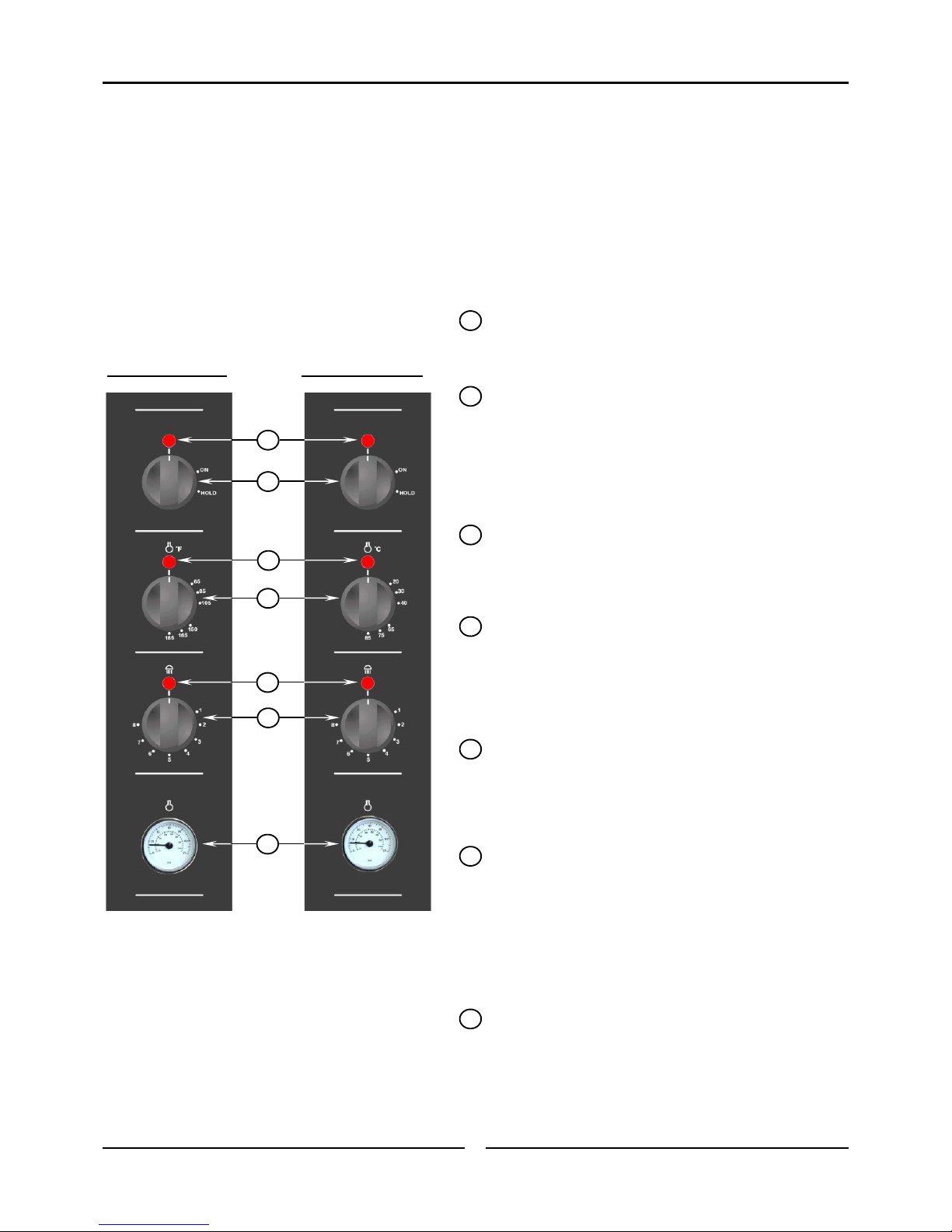
1. Set the Function Control (2) to ‘ON’.
The Power ‘On’ Indicator light (1) will illuminate when
the Function Control (2) is in the ‘ON’ position.
2. Set Thermostat Control (4) to desired proofing
temperature (20-40˚C / 65-105˚F).
The Heating ‘On’ Indicator light (3) will turn ’Off’ when
the cabinet has reached the set temperature.
3. Set Humidity Control (6) to the desired level.
As a general rule, set the humidity to between the 6 to
7 marks on the humidity control.
Increase or decrease the humidity control as required
for specific product types.
Humidity is required only to prevent the surface of the
product from dry skinning. Do not set the humidity to
high as the product will become sticky and wet on the
surface. A silky to touch surface on the product is a
general recommendation for correct humidity levels.
Avoid excess humidity levels as this will also create
excess condensation in the interior of the cabinet.
NOTE: Butter based product requires much less
humidity than breads
Operating in ‘Hold’ Mode
Ensure that power to the proofer / holding cabinet is
switched ‘On’.
1. Set the Function Control (2) to ‘HOLD’.
The ‘Power On’ Indicator light (1) will illuminate when
the Function Control (2) is in the ‘HOLD’ position.
2. Set the Thermostat Control (4) to the desired
Holding Temperature. (65-85˚C / 150-185˚F).
The Heating ‘On’ Indicator light (3) will turn ’Off’ when
the cabinet has reached the set temperature.
3. Humidity Control (6).
The humidity control function is not used in the ‘HOLD’
Mode. The setting on this dial will have no effect as the
wet element, water level sensor and water solenoid are
disabled.
4. Thermometer (7).
The thermometer will give an accurate reading of the
cabinet temperature to ensure that the product being
held is at the correct temperature.
Some parts of this proofer / holding cabinet
will become HOT during the Hold Mode and
could cause burns if touched accidentally.
Caution
Take care when opening the proofer /
holding cabinet door during the Proofing
Mode. Let hot air and steam escape before
removing or replacing food as the steam
produced can cause steam burns.
Caution

Cleaning
8
Cleaning Guidelines
To achieve the best results, cleaning must be regular and
thorough. If any small faults occur, have them looked at
promptly. Don't wait until they cause a complete
breakdown.
NOTE:
• Carefully read and follow the safety instructions on
the label of the cleaning product to be used.
• DO NOT use harsh abrasive scouring pads or
abrasive detergents as they could damage the oven.
• Ensure that any detergent or cleaning material has
been completely removed after each cleaning.
To keep your proofer / holding cabinet clean and operating
at peak efficiency, follow the procedures shown below:-
Proofer / Holding Cabinet Cleaning
NOTE:
• If the proofer / holding cabinet usage is very high,
the cleaning procedure should be carried out on a
more frequent basis.
Stainless Steel Surfaces
a. Clean the exterior surfaces of the proofer / holding
cabinet with, a damp cloth moistened with a mild
detergent solution, or a soft bristled brush.
b. Hardened deposits or discolouration may require a
good quality stainless steel cleaner. Always apply
cleaner when the appliance is cold and rub in the
direction of the grain.
c. Dry all components thoroughly with a dry cloth and
polish with a soft dry cloth.
d. Ensure that the proofer / holding cabinet chamber is
cool. Do not use wire brushes, steel wool or other
abrasive materials to clean the interior of the
cabinet.
e. Once a week, remove the side racks and water tank
and clean any build up of product from the proofer /
holding cabinet interior, using a mild anti bacterial
detergent and hot water solution and a soft bristled
brush.
f. Dry the proofer / holding cabinet thoroughly with a
soft dry cloth.
Side Racks
a. To remove the side racks for cleaning, take hold of
the centre rung of the rack and lift rack upwards.
b. Pull lower rack outwards to disengage the lower
rack key-holes from the lower hanger studs.
c. Lift the rack upwards to disengage the upper rack
key-holes from the upper hanger studs and lift the
rack out of the proofer / holding cabinet.
d. Clean the racks with a mild anti bacterial detergent
and a hot water solution, using a soft bristled brush.
Lower Hanger Studs
Lower Hanger Stud
Lower Rack Keyhole
Upper Rack Keyhole
and Hanger Stud
Always turn ‘Off’ the electrical power supply
at the mains supply before commencing
cleaning.
This proofer / holding cabinet is not water
proof. Do not use water jet spray to clean
interior or exterior of the appliance.
Caution

Cleaning
9
e. Dry the racks thoroughly with a dry cloth and polish
with a soft dry cloth.
f. To refit the racks, engage the front and rear upper
rack keyholes onto the upper hanger studs.
g. Raise the rack up again slightly until the lower rack
keyholes engage onto the lower studs, ensuring that
the upper studs remain engaged.
h. Push down on the rack to ensure that it is fully
engaged onto the upper and lower hanger studs.
NOTE: Ensure that the rack is securely fitted and that
ALL the studs are engaged into the rack key
holes.
Water Tank
It is recommended that this procedure is carried out
once a week. Frequency of cleaning the element
may be increased or decreased depending on the
quantity of scale depositing on the element.
a. To remove the water tank, remove the RH side rack
as shown previously.
b. Remove the water tank by lifting the tank off its
hanger studs. Clean with warm soapy water. Rinse
thoroughly and refit.
Water Tank Element
a. When the wet element becomes limed / scaled up,
remove the water tank and clean as shown
previously.
b. Refit the water tank and half fill with white vinegar
or acetic acid, then fill to the normal level with
water. Switch ‘On’ the unit, and turn the Humidity
Control to ‘8’. Operate for approximately 30
minutes.
c. When cooled, remove the water tank and clean the
element with a damp cloth. Rinse out the water
tank and refit to the unit.
Door
a. Wash with warm water and a mild detergent
solution using a soft sponge in straight lines up and
down the inner and outer surfaces of the door.
Rinse with clean, warm water and dry off.
b. Dry the door thoroughly with a soft dry cloth.
c. Clean door glass with a conventional glass cleaner.
Condensation Channel
a. Below the door is a condensation channel for
collecting door condensation run-off. This is then
fed into a condensation drawer.
b. Empty the condensation drawer on a regular basis
and once a week, wipe out the condensation
channel and drawer with a damp cloth moistened
with warm water and a mild detergent solution.
c. Dry with a soft dry cloth.
Door Seal
Clean the door seal with warm water and a detergent
solution using a soft sponge when required.
Should the door seal become dirty, it can be removed
for a more thorough cleaning should this be necessary:-
a. To remove the 1 piece seal, pull seal forward until it
pulls out of the location groove around the door.
b. Note the way the seal is fitted to the door,
with the lip facing inwards.
c. Check the seal for wear and damage and replace if
damaged or worn.
d. The seal may be washed in a sink, taking care not
to cut or damage the seal.
e. Dry the seal thoroughly with a soft dry cloth before
re-fitting.
f. To refit seal, have lip facing into the centre of door.
g. Press the seal into the locating groove around the
door until the seal is properly located.
Water Tank
Hanger Studs
Wet Element
Water Level Sensor
Water
Inlet
Condensation
Channel
Pull Seal out of locating channel
Condensation Drawer

Cleaning
10
Lamp Glass
The P8 and P12 proofer / holding cabinets are fitted
with 2 halogen lamps. These are fitted on the L/H inner
side panel, behind the L/Hand side rack.
a. To remove lamp glass, ensure that the L/Hand side
rack is removed as shown on the prevous page.
b. Unscrew the lamp glass anti-clockwise to remove.
c. Remove seal fitted between lamp glass and holder.
d. Wash the lamp glass and seal using a soft sponge
and warm water with a detergent solution. Rinse
with clean, warm water and dry off.
e. Dry the lamp glass thoroughly with a dry cloth.
NOTE: The lamp glass seal must be fitted with the flat
face of the seal towards the lamp glass.
f. To refit the lamp glass, screw in clockwise. Do not
over tighten the lamp glass.
g. Refit the L/Hand side rack as shown on the prevous
page.
Interior
Lamps
Unscrew Anti-Clockwise
Remove Seal

Fault Finding
11
This section provides a reference to the more common
problems that may occur during the operation of your
proofer / holding cabinet. This fault finding guide is
intended to help you correct, or at least accurately
diagnose problems with your proofer / holding cabinet.
When fault finding a problem, always use a process of
elimination starting with the simplest solution and working
through to the most complex. Never overlook the obvious.
You may encounter a problem not covered in this section,
please contact your service provider who will require the
following information:-
• The Model and Serial Number of the proofer /
holding cabinet, can be found on the Technical Data
Plate located on the front right hand side panel of
the cabinet.
Fault Possible Causes Remedy
The Proofer / Holding Cabinet does
not operate / start.
Mains isolating switch on the wall, circuit
breaker or fuses are 'Off' at the power board.
Function Control is faulty.
Turn 'On’.
Call for service.
The Proofer / Holding Cabinet lights
not illuminating.
Blown bulbs.
Function Control faulty.
Replace bulbs.
Call for service.
Fan does not operate.
Fan obstructed.
Fan motor faulty.
Function Control faulty.
Clear obstruction.
Call for service.
Call for service.
Door does not close.
Tray in way of door.
Door seal obstruction.
Correctly position tray in rack.
Correctly refit door seal. (Refer to the ‘Cleaning
and Maintenance’ Section).
Slow Recovery.
Overloading of cabinet.
Door opened unnecessarily.
Reduce batch size.
Do not open unnecessarily.
No Humidity.
Unit is in HOLD mode
Low water level in trough.
No water in trough.
Humidity set too low.
Humidity Thermostat faulty.
Wet Element faulty.
Switch unit to PROOF mode. (Humidity is only
generated in PROOF mode).
Solenoid or Float Switch faulty - Call for service.
Refer to ‘No Water Supply’ below.
Set humidity to higher setting.
Call for service.
Call for service.
No Dry Heat.
Function Control is ‘Off’.
Thermostat Control is ‘Off’.
Function Control faulty.
Thermostat Control faulty.
The element is faulty.
Turn ‘On’ the Function Control.
Turn ‘On’ the Thermostat Control.
Call for Service.
Call for Service.
Call for Service.
No Water Supply.
Water turned ‘Off’ at mains supply.
Water Solenoid faulty.
Float Switch faulty.
Relay Faulty.
Check mains supply and turn ‘On’ water.
Call for service.
Call for service.
Call for service.

Electrical Schematic
12
N/O
LIGHT
2x25W
HEATING ON
INDICATOR
N
E
L2
Ø
L1 P4 4
P2
P3
P1
2
3
1
POWER ON
INDICATOR
M
FAN
MOTOR
1 3 7
5
2 4 6 8
1
P
WATER
SOLENOID
HUMIDITY ON
INDICATOR
WATER
TANK
ELEMENT
650W 120V
600W 240V
WATER
TANK
THERMOSTAT
WATER
LEVEL
RELAY
WATER
LEVEL
FLOAT
SWITCH
HEATING
ELEMENT
P8M
700W 120V
800W 240V
P12M
1200W 120V
1200W 240V
HEATING
THERMOSTAT
1
P
HEATING CIRCUIT
HUMIDITY CIRCUIT
P4 4
P2
P3
P1
2
3
1
P4 4
P2
P3
P1
2
3
1
P4 4
P2
P3
P1
2
3
1
OFF PROOF HOLD
SWITCH SETTINGS
FUNCTION SWITCH
FUSE
10A
Electrical Schematic P8M - P12M Proofer Holding Cabinets.

Replacement Parts List
13
Item Description
P8 P12
234078 Wet Element, 240V, 600W
234079 Wet Element, 120V, 650W
234080 Dry Element, 240V, 1200W
234081 Dry Element, 120V, 1200W
234191 Dry Element, 240V, 800W
234190 Dry Element, 120V, 700W
013431K Fan Motor Kit, (208/240V, 50/60Hz)
025387K Fan Motor Kit, (120V)
022042 Fan Blade
021534 Relay, 240V
021535 Relay, 110V
024527 Humidity Thermostat, 30-85˚C / 86-185˚F
022787 Air Thermostat, 0-85˚C / 32-185˚F
022789 Switch - 3 Position
022788 Thermometer
234447 Knob Indexed
234803 Fuse 10A
234802 Fuse Holder 16A, 250V
234737 Indicator Red LED 9 mm, 110 - 250V
233115 Oven Lamp Lens
233883 Oven Lamp Seal
231814 Lamp Bulb, G9, 25W, Halogen, 230V
233884 Lamp Bulb, G9, 25W, Halogen, 120V
234570 Door Seal - P8
234537 Door Seal - P12
233528 Float Switch
234348 Water Solenoid, 90˚Outlet, 240V
234349 Water Solenoid, 90˚Outlet, 120V
234324 Rack LH - P8
234325 Rack RH - P8
234328 Rack LH, 12 Tray, P12
234329 Rack RH, 12 Tray, P12
234661 Rack LH, 9 Tray, P12
234662 Rack RH, 9 Tray, P12
234216 Castor 75 mm, Rigid Rubber
234217 Castor 75 mm, Swivel Rubber d/brake
234347 Filter Head Kit Optional
234562 Water Filter Cartridge Optional
018947 Magnet Catch
234626 Door Hinge Top
234627 Door Hinge Bottom
When ordering replacement parts, please quote the part number and the description as listed below. If the part required
is not listed below, request the part by description and quote model number and serial number which is shown on the
Technical Data Plate.
Important:
Only genuine authorized replacement parts should be used for the servicing and repair of this proofer / holding
cabinet. The instructions supplied with the parts should be followed when replacing components.
For further information and servicing instructions, contact your nearest authorized service provider or Turbofan Dealer.

This manual suits for next models
1
Table of contents
Other Moffat Food Warmer manuals
Popular Food Warmer manuals by other brands

STODDART
STODDART AXH.FDCTSQ.09 Specification, installation and operation manual

GE
GE Panda iRes Warmer Operation and maintenance manual

Pro-Idee
Pro-Idee 653-444 manual

Delfield
Delfield 48000 Series Service and installation manual

Henny Penny
Henny Penny HCD-930/932 Product information

APW Wyott
APW Wyott FD Installation and operating instructions

Avantco Equipment
Avantco Equipment 177BMFW3 user manual

BevLes
BevLes Wall Mount/Under Counter Proofer/Holding Cabinet... Installation and operating instructions

Adler
Adler AD 6304 user manual

Antunes
Antunes DCH-320 SQ owner's manual

HURAKAN
HURAKAN HKN-RH1 manual

Bloomfield
Bloomfield HT-200 Operation manual